Note : Les descriptions sont présentées dans la langue officielle dans laquelle elles ont été soumises.
CA 02366985 2001-09-06
WO 00/55658 PCT/KR00/00200
-1-
TITLE OF THE INVENTION
TEMPERATURE COMPENSATED LONG PERIOD OPTICAL FIBER
GRATING FILTER
Field of the Invention
The present invention relates to a temperature compensated long period optical
fiber grating filter.
Description of the Related Art
Generally, a long period optical fiber grating filter is an optical device for
coupling modes propagated in the core of an optical fiber to modes propagated
in the
cladding of the optical fiber. Such a long period optical fiber grating filter
provides
an advantage in terms of the gain flatness of erbium-doped optical fiber
amplifiers
(EDFAs) in that it is of a mode-coupling type other than a reflective mode-
coupling
type. Such a long period optical fiber grating is manufactured to exhibit a
periodic
variation in refractive index at its core. The periodic variation in
refractive index is
obtained by periodically exposing the core of an optical fiber, sensitive to
ultraviolet
rays, in the optical fiber grating to ultraviolet rays in the process of
manufacturing the
optical fiber grating. That is, an increase in refractive index is exhibited
at portions
of the core exposed to ultraviolet rays whereas no variation in refractive
index occurs
at the remaining portions of the core not exposed to ultraviolet rays. Thus, a
periodic
variation in refractive index is exhibited in the core. In such a long period
optical fiber
grating, a mode coupling occurs in a state in which a phase matching condition
expressed by the following Expression 1 is satisfied.
[EXPRESSION 1] (3~0 - ~i~,~°'' = 2/11
where, (3~o represents a propagation constant of a core mode, ~i~, represents
a
propagation constant of an m-th cladding mode, and l1 represents a grating
period.
Where ~3 = 2~n/~, is substituted into Expression 1 ("n" represents a
refractive
index, and ~, represents a wavelength), the refractive index difference
between the core
CA 02366985 2004-O1-20
wo oorsss~s ~crrhuooroo~oo
and cladding modes is derived which corresponds to n~o - n_,~"'? = a.l A.
Accordinjly,
a chance of light with a certain lvavelena h into a cladding mode can be
achieved by
appropriately determining a desired D ating period 1~ and a desired refractive
index
difference n~o - n~,~°''.
A desired refractive index difference can be obtained by appropriately
radiating
an ultraviolet laser onto the optical fiber which is sensitive to ultraviolet
rays. That is,
the optical fber sensitive to ultraviolet rays is masked by a mask having a
particular
period . When a laser is then radiated onto the mask, the opto-sensitive
optical fiber
generates a reaction resulting in a variation in the refractive index ofthe
core. In order
to obtain a desired spectrum, that is, a desired coupling wavelength and a
desired
extinction ratio, the radiation of the ultraviolet laser should be carried out
for an
appropriate period of time by accurately adjusting the mask period.
The coupling wavelength of the long period optical fiber grating manufactured
as mentioned above is also influenced by temperature. A shift of coupling
wavelength
I ~ depending on a variation in temperature is based on a variation in
refractive index
depending on the temperature variation and a thermal expansion in length
depending
on the temperature variation. This can be expressed by the following
Expression 2:
dl n' d i? d~'~ dA
- =
[EXPRESSIOl~ 2] dT do dT ~ dry dT
where, T represents a temperature.
~~Vhere a Ions period optical fiber grating is applied to general optical
fibers for
communication or dispersion shifted optical fibers, the second term of the
right side
in Expression 2 is not taken into consideration because the value defined by
the first
term of the right side in Expression 2 is greater than the value defined by
the second
TM
term ,by about several ten times. For instance, the Flexcor I 060 manufactured
by
2~ Corning Glass Corporation exhibits a coupIin~ wavelength of about 5 nm per
I OOC.
Typical dispersion shifted optical fibers exhibit a coupling wavelength shift
of about
CA 02366985 2001-09-06
WO 00/55658 PCT/KR00/00200
-3-
0.3 nm per 100C due to a variation in refractive index occurs while exhibiting
a
coupling wavelength shift of about S nm per 100C due to a length expansion. In
the
case of a gain flattening filter, which is an example of a practical
application of long
period optical fiber gratings, however, a temperature stability of about 0.3
nm per
100C is required.
In order to obtain a temperature compensation meeting the above requirement,
a method has been used in which the refractive index of the filter is adjusted
in such
a fashion that the term d~,/dl1 in Expression 2 has a negative value. There is
another
conventional method in which the period of the long period optical fiber
grating is
shortened in such a fashion that a higher-order cladding mode is selected.
Another
method is also known in which an addition ofB203 is made to allow the term
"dn/dT"
in Expression 2 to have a value of 0.
However, all the above mentioned conventional methods use complicated
processes because they involve a refractive index adjustment in the filter or
an addition
of a material serving to avoid a variation in refractive index caused by a
variation in
temperature. U.S. Patent No. 5,757,540 for Long-Period Fiber Grating Devices
Paclzaged For Temperature Stability to Judkins et al discloses a material
package
surrounding the cladding about the long-period grating for temperature
stability.
However, Judkins et al '540 does not disclose coating the region of the
optical fiber
cladding absent from a long period grating. What is needed is an optical fiber
with
two separate coatings, one for the region containing the long period grating
and the
other for the region absent the long period grating. This would result in an
optical
fiber with a uniform diameter in all regions which is easier to handle and
use.
SUMMARY OF THE INVENTION
Therefore, an object of the invention is to provide a long period optical
fiber
grating filter which is coated with a material serving to shift a coupling
wavelength of
the filter in a direction opposite to that of a coupling wavelength shift
caused by a
variation in temperature.
It is another object to apply one type of coating to the cladding surrounding
a
CA 02366985 2001-09-06
WO 00/55658 PCT/KR00/00200
-4-
long period grating in the optical fiber and to apply a separate and different
coating to
the cladding surrounding portions of the optical fiber absent of the long
period grating.
It is yet another object to have the two different coatings adjacent to each
other
and have equal inner and outer radiuses so that the fiber construction is
smooth and
S has a uniform diameter throughout the length of the optical fiber.
In accordance with the present invention, this object is accomplished by
providing a long period optical fiber grating filter comprising: a core formed
with a
long period grating; a cladding surrounding the core; a coating coated over a
portion
of the cladding not surrounding the long period grating; and a re-coating
coated over
a portion of the cladding surrounding the long period and made of a material
exhibiting an increase in refractive index in accordance with an increase in
temperature, the re-coating serving to allow a coupling wavelength shift
caused by the
increase in refractive index to be carned out in a direction opposite to that
of a
coupling wavelength shift caused by a refractive index difference between the
core and
1 S the cladding.
BRIEF DESCRIPTION OF THE DRAWINGS
A more complete appreciation of this invention, and many of the attendant
advantages thereof, will be readily apparent as the same becomes better
understood
by reference to the following detailed description when considered in
conjunction with
the accompanying drawings, in which like reference symbols indicate the same
or
similar components, wherein:
Fig. lA is a cross-sectional view illustrating a long period optical fiber
grating
filter;
Fig. 1B is a view illustrating an operation in the long period optical fiber
grating filter of Fig. 1 A to couple a core mode to a cladding mode;
Figs. 2A to 2D are graphs depicting different coupling peak shifts depending
on different refractive indicia exhibited around the cladding, respectively;
Fig. 3 is a graph depicting a coupling wavelength shift depending on the
refractive index exhibited around the cladding;
CA 02366985 2001-09-06
WO 00/55658 PCT/KR00/00200
-5-
Fig. 4 is a graph illustrating a coupling wavelength shift exhibited at each
mode
order of an optical signal passing through the long period grating, depending
on a
variation in refractive index exhibited around the cladding; and
Figs. SA to SD illustrate a temperature compensation mechanism of the long
period grating filter according to the present invention, respectively.
DETAILED DESCRIPTION OF THE INVENTION
Fig. lA is a cross-sectional view illustrating a long period optical fiber
grating
filter. As shown in Fig. 1 A, the long period optical fiber grating filter
includes an
optical fiber having a core 102 formed with a long period grating 100, a
cladding 104
surrounding the core 102 along with the long period grating 100, and a coating
surrounding the cladding 104.
The long period grating 100 is formed by partially removing the coating 106
of the optical fiber, which is sensitive to ultraviolet rays, and then
radiating an
ultraviolet laser onto the optical fiber while using an amplitude mask (not
shown)
adapted to transmit the ultraviolet laser at intervals of a certain period,
thereby
inducing a periodic refractive index variation in the core 102.
Fig. 1 B illustrates an operation in the long period optical fiber grating
filter of
Fig. lA to couple a core mode to a cladding mode. A fundamental guided mode
110
propagating in the core 102 is scattered while passing through refractive
index
variation regions 112. The scattered light, which is denoted by the reference
numeral
114, is coupled to the cladding 104, so that it is coherently reinforced to
have a
wavelength meeting a desired phase matching condition. As the light having the
above wavelength is emitted from the cladding 104, the long period optical
fiber
grating filter operates as a wavelength-dependant attenuator. The fundamental
guided
mode is attenuated in intensity while passing through the refractive index
variation
regions 112. On the other hand, the light having the wavelength coupled to the
cladding 104 exhibits a gradual increase in intensity. In Fig. 1B, a higher
intensity of
light is indicated by a thicker arrow. Each of the refractive index variation
regions 112
corresponds to the long period grating shown in Fig. lA.
CA 02366985 2001-09-06
WO 00/55658 PCT/KR00/00200
-6-
The ambient condition around a portion of the cladding, where the long period
grating as mentioned above is arranged, is air having a refractive index of 1.
Where
the cladding is re-coated with a material having a refractive index of n after
the
formation of the long period grating, a variation in coupling condition
occurs. As a
result, the coupling wavelength is shifted toward a longer wavelength or
toward a
shorter wavelength.
Figs. 2A to 2D depict different coupling peak shifts depending on different
refractive indicia exhibited around the cladding, respectively. Fig. 2A
illustrates
transmission characteristics of light in the case in which the refractive
index exhibited
around the cladding of a long period grating is 1. Fig. 2B illustrates
transmission
characteristics of light in the case in which the refractive index exhibited
around the
cladding of the long period grating is 1.400. Referring to Figs. 2A and 2B, it
can be
found that an increase in extinction ratio occurs in accordance with an
increase in
refractive index exhibited around the cladding. Fig. 2C illustrates
transmission
characteristics of light in the case in which the refractive index exhibited
around the
cladding of the long period grating is 1.448. Referring to Fig. 2C, it can be
found that
the coupling wavelength is shifted toward a shorter wavelength by about 16.5
nm.
Fig. 2D illustrates transmission characteristics of light in the case in which
the
refractive index exhibited around the cladding of the long period grating is
1.484.
Referring to Fig. 2D, it can be found that the coupling wavelength is shifted
toward
a longer wavelength, as compared to the case in which the refractive index
exhibited
around the cladding is 1. In this case, a decrease in extinction ratio also
occurs.
Thus, a coupling wavelength shift toward a shorter wavelength occurs when the
refractive index exhibited around the cladding increases from 1 while being
less than
the refractive index of the cladding, as in the case of Fig. 2B or 2C.
However, when
the refractive index exhibited around the cladding exceeds the refractive
index of the
cladding, a coupling wavelength shift toward a longer wavelength occurs, as in
the
case of Fig. 2D. Where the refractive index exhibited around the cladding is
equal to
the refractive index of the cladding, the total reflection condition is lost,
so that
coupling peaks disappear.
Fig. 3 depicts a coupling wavelength shift depending on the refractive index
CA 02366985 2004-O1-20
wo flo~s~s~s ~cr~xoo~oo~oo
exhibited around the cladding. Referring to Fig. 3, it can be found that the
coupling
wavelength is shifted toward a shorter wavelength as the refractive index
exhibited
around the cladding increases from 1. When the refractive index around the
cladding
is rendered to be equal to the refractive index of the cladding, coupling
peaks
disappear. As the refractive index around the cladding exceeds the refractive
index
of the cladding, the coupling wavelength is shifted toward a longer
wavelength.
In order to vary the refractive index exhibited around the cladding, the
coating
of the optical fiber is removed at a region where the long period orating is
formed, in
accordance with the present invention. The portion of the optical fiber
exposed after
the partial removal ofthe coating is re-coated with a material exhibiting a
variation in
refractive index depending on a variation in temperature. Preferably, the re-
coating
material exhibits an increase in refractive index in accordance with an
increase in
temperature. As the r efractive index ofthe re-coating material increases, the
coupling
wavelength of the long period orating is shifted toward a shorter wavelength.
I~ Ifthe re-coating material exhibits a decrease in refractive index in
accordance
with an increase in temperature, the coupling wavelength of the long period
~ratin~
TM
is then shifted toward a longer wavelength. For example, the Flexcor 1060
manufactured by Coming Glass Corporation exhibits a temperature sensitivity of
about
~ nm per 1 OOC where it is not coated with the above mentioned re-coating
material.
?0 1-3owever, where the Flexcor 1060 is coated with silicon resin as the above
mentioned
re-coating material, it exhibits a temperature sensitivity of about 10 nm per
100C.
This effect results from an effect ofthe coupling wavelength shifted toward a
longer
wavelength due to a decrease in the refractive index of the silicon resin,
used as the
re-coating material, in accordance with an increase in temperature, in
addition to a
25 phenomenon of the coupling wavelength shifted toward a longer wavelength in
accordance with the first term of the right side in Expression ~1 as mentioned
above.
Accordingly, a desired temperature compensation effect can be obtained by
usinV, as a re-coating material, a material exhibiting an increase in
refractive index in
accordance with an increase in temperature. Such a re-coating material for the
30 temperature compensated Iongperiod grating filter should have desired
characteristics.
That is, the re-coating material should have an initial refractive index less
than that the
CA 02366985 2001-09-06
WO 00/55658 PCT/KR00/00200
_g_
refractive index of the material of the cladding, for example, pure silica,
while having
characteristics capable of exhibiting an increase in refractive index in
accordance with
an increase in temperature, thereby shifting the coupling wavelength of the
grating
toward a shorter wavelength.
Fig. 4 is a graph illustrating a coupling wavelength shift depending on a
variation in refractive index exhibited around the cladding. In Fig. 4, the
reference
characters LPO l to LPOP represent respective mode orders of an optical signal
passing
through the long period grating. The mode order of the optical signal
increases along
the vertical axis of the graph shown in Fig. 4. Referring to Fig. 4, it can be
found that
the coupling wavelength at each mode order is shifted toward a shorter
wavelength in
accordance with an increase in the external refractive index.
Figs. SA to SD illustrate a temperature compensation mechanism of the long
period grating filter according to the present invention, respectively. Fig.
SA depicts
refractive index variation characteristics of the re-coating material
depending on
temperature. Referring to Fig. SA, it can be found that an increase in
refractive index
occurs in accordance with an increase in temperature. Fig. SB depicts a
coupling
wavelength shift depending on an external refractive index exhibited around
the
cladding. Referring to Fig. SB, it can be found that the coupling wavelength
is shifted
toward a shorter wavelength in accordance with an increase in external
refractive
index. Fig. SC depicts a coupling wavelength shift depending on temperature.
Referring to Fig. SC, it can be found that an increase in temperature causes
an increase
in the refractive index of the re-coating material, thereby resulting in a
coupling
wavelength shift toward a shorter wavelength.
On the other hand, Fig. SD depicts a temperature compensation effect of the
long period grating exhibited depending on temperature. In Fig. SD, the graph
500
depicts a coupling wavelength shift depending on the temperature of the re-
coating
material. The graph 502 depicts a coupling wavelength shift depending on a
refractive
index difference between the core and cladding exhibited depending on
temperature.
The graph 504 is a graph depicting a result obtained after a compensation
between the
coupling wavelength shifts respectively shown in the graphs 500 and 502.
Referring
CA 02366985 2001-09-06
WO 00/55658 PCT/KR00/00200
-9-
to the graph 504, it can be found that there is no coupling wavelength shift
even when
an increase in temperature occurs.
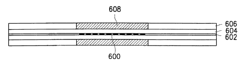
Fig. 6 is a cross-sectional view illustrating the structure of the temperature
compensated long period grating filter according to the present invention. In
Fig. 6,
the reference numeral 600 denotes the long period, 602 the core, 604 the
cladding
surrounding the long period grating and core, 606 the coating, and 608 the re-
coating
surrounding the portion of the cladding arranged at the region where the long
period
grating is formed. As mentioned above, the re-coating is preferably made of a
material
having a refractive index increasing in accordance with an increase in
temperature
I 0 while being less than the refractive index of the cladding.
In accordance with the present invention, it is possible to compensate for a
coupling wavelength shift occurring due to an increase in temperature by re-
coating
a material, exhibiting an increase in refractive index in accordance with an
increase
in temperature, over the long period grating. Accordingly, a temperature
compensation can be more easily achieved in accordance with the present
invention,
without any inconvenience caused by an adjustment of refractive index in the
filter or
an addition of a material for avoiding a variation in refractive index
depending on
temperature.
While the present invention has been particularly shown and described with
reference to a particular embodiment thereof, it will be understood by those
skilled in
the art that various changes in form and detail may be effected therein
without
departing away from the scope of the invention as defined by the appended
claims.