Note : Les descriptions sont présentées dans la langue officielle dans laquelle elles ont été soumises.
CA 02369102 2001-10-05
- 1 - NI009
DESCRIPTION
WIPER FOR MACHINE TOOL
TECHNICAL FIELD
The present invention relates to a wiper for machine
tools which is operated on sliding surfaces of machine tools
and industrial machines to scrape chips, cutting lubricants,
and the like which are present on the sliding surfaces, for
the purpose of preventing these chips and cutting lubricants
from entering the sliding surfaces.
BACKGROUND ART
Conventionally, a wiper used to remove chips and
cutting lubricants from a machine tool includes a lip portion
having a sliding portion which is typically made of a rubber
material. The reason a rubber material is adopted is that
the elasticity thereof is utilized to improve the conforming
and scraping capabilities of the wiper in all directions.
Recently, a machine system which does not use a
cutting lubricant (dry cutting) in order to avoid
environmental issues, a high-speed type machine tool, and
the like have been developed. Especially for these machines,
a sliding portion of a wiper suffers from significant
abrasion due to the high coefficient of friction of rubber
and therefore, the closeness of the sliding portion of the
wiper to the sliding surface cannot long for a long time.
To address the above problem, a wiper including a
sliding portion made of thin spring steel has been proposed.
, 1 ~ 1, ..
CA 02369102 2004-12-07
- 2 -
However, when such a wiper is transported in a package made
of corrugated cardboard, the wiper is often deformed due
to its thinness, causing inconvenience of handling.
Further, when such a wiper is used, scattered chips strike
and bend the spring steel, resulting in a reduction in the
closeness of the wiper. Furthermore, since spring steel is
a metallic material, sliding surfaces may be damaged, or
the spring steel may be corroded.
DISCLOSURE OF THE INVENTION
A wiper for machine tools according to the present
invention includes an attachment portion to be attached to
a machine tool, wherein the machine tool is moved relative
to a sliding surface, and a wiper body made of an elastic
material integrated with the attachment portion. A lip
portion of the wiper body can be slid on the sliding surface,
and a fabric material is provided on at least a sliding
surface of the lip portion of the wiper body.
In one embodiment, the fabric material is made of
at least one material selected from the group consisting
of aromatic polyamide, aliphatic polyamide, and polyester.
In one embodiment, the lip portion of the wiper body
is covered with the fabric material.
In one embodiment, the fabric material is made of
weave fabric or knit fabric, and a thickness of the fabric
material is 0.5 mm or more.
In one embodiment, a fineness of a thread included
in the fabric material is 100 deniers or more.
CA 02369102 2001-10-05
- 3 - NI009
In one embodiment, a coefficient of friction of a
thread included in the fabric material is in the range of
0.1 to 0.3.
Since a fabric material is provided on at least a
sliding side of a lip portion of a wiper, the coefficient
of friction of the lip portion with a sliding surface is
reduced and abrasion loss is reduced. Therefore, closeness
can be maintained for a long time. Further, the low
coefficient of friction allows the wiper to be slid at a
high rate. Further, since a sliding portion of the lip
portion includes a fabric material, a sliding surface does
not suffer from scratches which would be otherwise observed
when the sliding portion is made of a metallic material.
A defective product due to warpage of a wiper caused by
collision or impact with chips, or the like, can be avoided.
When a fabric material ( fabric layer ) to be abraded
by fast sliding operations has a small thickness, a wiper
body made of an elastic material, such as rubber, underlying
the fabric material is exposed. In this case, friction
resistance is increased and abrasion is rapidly increased.
To avoid this, the thickness of a fabric material
( original fabric ) is set to be 0 . 5 mm or more ( particularly
1 mm or more), or the fineness of a thread included in the
fabric material is set to be 100 deniers or more
(particularly, the fineness of wefts extending in a
direction perpendicular to a sliding direction is set to
400 deniers or more ) . Therefore, the life of the wiper can
be lengthened in fast sliding operations.
"".
CA 02369102 2004-12-07
- 4 -
According to the present invention, at least a lip
portion of a wiper body is covered with a fabric material,
whereby the friction resistance of the lip portion is small
and therefore a fast sliding operation can be performed and
the amount of leaked chips is small over long-term use.
Further, since a sliding portion of the lip portion
includes a fabric material, a sliding surface does not
suffer from scratches which would be otherwise observed
when the sliding portion is made of a metallic material. A
defective product due to-warpage of a wiper caused by
collision or impact with chips, or the like, can be
avoided.
Therefore, the wiper of the present invention can be
used for machine tools which are moved at a high speed.
Further, since scraping can be satisfactorily performed in
an operation without cutting oil, the wiper of the present
invention is applicable to particular operations, such as
aluminum cutting.
According to an aspect of the present invention,
there is provided a wiper for a machine tool comprising: an
attachment portion to be attached to the machine tool,
wherein the machine tool is moved relative to a sliding
surface; and a wiper body made of an elastic material
integrated with the attachment portion, wherein a lip
portion of the wiper body can be slid on the sliding
surface, and a fabric material is provided on at least a
sliding surface side of the lip portion of the wiper body,
wherein the fabric material is made of weave
fabric, and wefts of the weave fabric being orthogonal to a
sliding direction of the lip portion, the fineness of the
wefts being in the range of 80 to 500 deniers, the fineness
1. " li
CA 02369102 2004-12-07
- 4a -
of the warps being 40 deniers to 250 deniers, and the
fineness of the warps being smaller than that of the wefts.
BRIEF DESCRIPTION OF THE DRAWINGS
Figure 1 is a cross-sectional view of a wiper
according to an embodiment of the present invention.
Figure 2 is a cross-sectional view of a wiper
according to another embodiment of the present invention.
Figure 3 is a cross-sectional view of a wiper
according to still another embodiment of the present
invention.
Figure 4 is a diagram for explaining a method for
measuring a pressing force of a wiper.
CA 02369102 2001-10-05
- 5 - NI009
Figure 5 is a diagram for explaining a method for
measuring a sliding resistance of a wiper.
Figure 6 is a diagram for explaining a method for
testing a sliding operation of a wiper.
Figure 7 is a cross-sectional view of a conventional
wiper.
Figure S is a cross-sectional view of another
conventional wiper.
Figure 9 is a cross-sectional view of a wiper
according to still another embodiment of the present
invention.
Figure 10 is a cross-sectional view of a major
portion of the wiper of Figure 9.
BEST MODE FOR CARRYING OUT THE INVENTION
Hereinafter, the present invention will be
described with reference to the accompanying drawings.
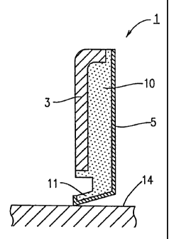
Referring to Figure 1, a wiper 1 for machine tools
according to the present invention includes an attachment
portion 3 attached to a machine tool which is reciprocated
with respect to a sliding surface 14 (e. g. , a machine surface
or a cover surface), and a wiper body 10 which is made of
an elastic material and is integrated with the attachment
portion 3.
CA 02369102 2001-10-05
- 6 - NI009
The attachment portion 3 is also called a cored bar
and is typically made of a metallic material.
The wiper body 10 is formed as a long member which
transversely extends. A lip portion 11 is provided at a
lower portion of the wiper body 10, a thickness of which
is gradually decreased toward a tip side thereof.
Preferably, the wiper body 10 is made of an elastic material,
such as NBR, urethane rubber, fluorocarbon rubber, or H-NBR,
is oil-resistant, and has a suitable elasticity in the
hardness range of 70 to 90 (typically 70).
For the wiper body 10, at least the lip portion 11
is covered with a fabric material 5.
The fabric material 5 may be made of one or more
synthetic fibers (e. g., aliphatic polyamide, aromatic
polyamide, and polyester) , natural fiber, glass fiber, and
metal fiber having a relatively low stiffness, and
preferably made of a synthetic fiber, such as aliphatic
polyamide, aromatic polyamide, or polyester. The fabric
material 5 may be in the form of weave fabric, knit fabric,
or the like, and is preferably in the form of weave fabric.
Referring to Figure 9, when the fabric material 5
is in the form of weave fabric or knit fabric, the thickness
of the fabric material is preferably in the range of 0.25 mm
to 2.0 mm, more preferably 0.5 mm to 1.5 mm, and even more
preferably 0.5 mm to 1.0 mm. The fineness of the fibers of
the fabric material is preferably in the range of 50 deniers
to 500 deniers, and more preferably 100 deniers to
450 deniers.
CA 02369102 2001-10-05
- 7 - NI009
Particularly, the fabric material 5 is provided at
a sliding surface side of the lip portion il in such a manner
that wefts 5a of the weave or knit fabric are orthogonal
to a sliding direction of the lip portion 11. As such, the
fineness of the wefts 5a is preferably in the range of
80 deniers to 500 deniers , and more preferably 100 deniers
to 450 deniers. The fineness of the warps 5b may be about
half the fineness of the wefts 5a, for example, 40 deniers
to 250 deniers, and more preferably 50 deniers to
200 deniers.
When the fineness of the wefts 5a is thus greater
than that of the warps 5b, the life of the wiper 1 can be
lengthened in high-speed operation. If the stiffness of a
waist portion of the lip portion il is excessively increased,
the stiffness of the wiper itself is increased and therefore
the pressing force of the lip portion 11 is increased. This
problem can be solved by the fineness of the warps 5b being
smaller than that of the wefts 5a. Taking into
consideration the linear shape of the edge of the lip
portion 11, the area where the fabric material 5 makes
contact with the sliding surface is increased, so that the
life of the wiper is expected to be lengthened.
The fabric material 5 may be subjected to adhesion
treatment or rubber impregnation treatment.
The fabric material 5 may be adhered to a lower
surface of the lip portion 11 of the wiper body 10 using
an adhesive or by vulcanization.
As shown in Figure l, the fabric material 5 may
cover the wiper body 10, specifically, the lip portion 11
CA 02369102 2001-10-05
- 8 - NI009
and a side surface of the wiper body 10. As shown in
Figures 2 and 3, upper and lower surfaces of the lip
portion li of the wiper body 10 and the side surface of the
wiper body 10 may be covered with the fabric material 5.
Referring to Figure 10, the fabric material 5 may
be provided on the lower surface ( sliding surface ) of the
lip portion 11.
When the lip portion 11 of the wiper body 10, which
is made of an elastic material (e. g., rubber), is thus
protected by the fabric material 5, the coefficient of
friction of the lip portion 11 with respect to the sliding
surface 14 is smaller than that of a conventional lip
portion of rubber without a fabric material cover.
Therefore, abrasion loss can be reduced, whereby closeness
can be maintained for a long time. Although a conventional
wiper including a sliding portion made of a metallic material
has a low level of sliding resistance, the amount of chips
leaked during an actual sliding operation is larger in the
conventional wiper than in the wiper of the present invention .
A wiper has a higher level of closeness when a sliding portion
is made of elastic rubber. In this case, the sliding
resistance is smaller than that of conventional sliding
portions than when the sliding portion is made of a metallic
material having a higher level of rigidity. Synthetic
fibers used in weave fabric or the like have a small
coefficient of friction ( typically, 0 .1 to 0. 3 ) . Synthetic
fibers are also deformable and therefore do not hinder
elastic deformation of the rubber. Therefore, the wiper 1
covered with the fabric material 5 made of synthetic fiber
can be slid without losing closeness.
CA 02369102 2001-10-05
- 9 - NI009
The outer surface of the lip portion il of the wiper
body 10 is provided with the fabric material 5, so that the
fabric material 5 makes contact with the sliding surface 14 .
Therefore, the frictional resistance of the wiper sliding
portion is decreased, whereby abrasion can be reduced and
the sliding surface 14 is prevented from being damaged.
Next, an exemplary method for producing the wiper
of the present invention will be described.
The fabric material 5 ( a . g . , weave fabric made of
a synthetic resin fiber) is provided on a predetermined
portion of a mold. The mold is filled with unvulcanized
rubber. The unvulcanized rubber is then vulcanized. The
wiper body 10 is thus produced and at the same time the fabric
material 5 is vulcanized to be adhered to the wiper body 10.
In this case, a portion of the unvulcanized rubber is
vulcanized while permeating the fabric material 5 or
passing through stitches of the fabric material 5, whereby
the wiper body 10 and the fabric material 5 are integrated
together and therefore the adhesive strength therebetween
is enhanced.
As shown in Figures 1 to 3, the present invention
is applicable to wipers having various sizes and shapes for
the purposes of removing chips and coolant produced during
operations of machine tools and industrial machines.
(Examples)
Next, the present invention will be specifically
described by way of illustrative examples.
Evaluation methods which are used in the following
CA 02369102 2001-10-05
- 10 - NI009
examples will be described below.
( 1 ) Method for measuring a pressing force of a wiper
A. Testing method
Figure 4 shows a testing instrument. In Figure 4,
reference numeral 6 indicates a load cell, reference
numeral 7 indicates a saddle, and reference numeral 1
indicates a wiper.
The wiper 1 is fixed to the saddle 7. The wiper 1
is moved downward until a tip portion of the lip portion 11
of the wiper 1 touches a surface of the load cell 6. The
wiper 1 is further moved by 0. 5 mm to press the load cell 6.
A force exerted on the load cell 6 is sensed by the load
cell 6. Such a force is defined as a pressing force. The
pressing force is typically represented in units of per
centimeter. The pressing force is used as a vertical load
(W) in the following section (manual resistance
measurement).
B. Testing conditions: No lubricant
( 2 ) Method for measuring a sliding resistance of a
wiper
A. Testing method
Figure 5 shows a testing instrument. In Figure 5,
reference numeral 6 indicates a load cell, reference
numeral 7 indicates a saddle, reference numeral 1 indicates
a wiper, and reference numeral 8 indicates a sliding bed.
While the wiper 1 is fixed to the saddle 7, the
sliding bed 8 is moved in a direction indicated by an arrow.
A force F exerted on the load cell 6 in a horizontal
CA 02369102 2001-10-05
- 11 - NI009
direction is sensed by the load cell 6. A coefficient of
friction ~, is calculated based on the force F and the
vertical load W (a force generated when a wiper is pressed
by a specified value of 0.5 mm) in accordance with an
expression:
F = ~,~,W
where F represents a sliding resistance (Kgf ) , ~, represents
a coefficient of friction, and W represents a pressing force
(Kgf ) .
B. Testing conditions:
No lubricant
Sliding rate of 10 m/min
(3) Method for testing a sliding operation of a
wiper
A. Testing method
Figure 6 shows a specimen and a testing instrument .
In Figure 6, reference numeral 7 indicates a saddle,
reference numeral 1 indicates wipers, reference numeral 8
indicates a sliding bed, and reference numeral 3 indicates
cored bars of the wipers 1.
The wipers 1 are fixed on the opposite sides of the
saddle 7 as shown in Figure 6. The sliding bed 8 is
reciprocated while chips 9 are confined between the
wipers 1. A distance traveled by a sliding portion 11 of
the wiper 1 is calculated based on a sliding stroke of the
sliding bed 8. The amount of chips which are leaked through
the lip portions 11 of the wipers 1 and are present on the
opposite ends of the sliding bed 8 is measured for different
CA 02369102 2001-10-05
- 12 - NI009
distances.
The wiper 1 used has the same cross-sectional shape
as that of a standard product, and has a width of 120 mm.
The wiper 1 is pressed by a specified value of 0 . 5 mm ( such
a value is 3 mm for a wiper including a sliding portion made
of spring steel).
B. Testing conditions:
No lubricant
Sliding rate of 25 m/min
Sliding stroke of 215 mm
Room temperature environment
(Comparative Example 1)
A cored bar was placed in a mold. The mold was filled
with unvulcanized NBR followed by vulcanization. A wiper
including a cored bar 3 and a wiper body 10 as shown in
Figure 7 was obtained.
This wiper was used, and the pressing force, sliding
resistance and the amount of leaked chips were measured.
The results are shown in Table 1.
(Comparative Example 2)
A wiper body 10 was made of NBR. A thin metal
plate 12 was adhered to a lower surface of a lip portion 11
of the wiper body 10 by vulcanization, thereby obtaining
a wiper 1 as shown in Figure 8.
The wiper 1 was used, and the pressing force,
sliding resistance and the amount of leaked chips were
measured. The results are shown in Table 1.
CA 02369102 2001-10-05
- 13 - NI009
(Example 1)
A cored bar and a weave fabric made of synthetic
fibers were placed in a mold. The mold was filled with
unvulcanized NBR followed by vulcanization. As a result,
the wiper 1 including the cored bar 3 and the wiper body 10
as shown in Figure 1 was obtained. A lip portion il of the
wiper body 10 was covered with the weave fabric 5.
The wiper 1 was used, and the pressing force,
sliding resistance and the amount of leaked chips were
measured. The results are shown in Table 1.
Table 1
Type of Comparative Comparative Example
wiper Example 1 Example 2 1
Measured
item
Pressing 133 50 181
force
(gf/cm)
Sliding 71 19 48
resistance
(gf/cm)
Amount 5 km of travel 0.06 0.10 0.05
of
leaked 15 km of travel0.12 0.16 0.09
chips 30 km of travel0.25 0.19 0.11
in
sliding
test (g)
The results shown in Table 1 indicate the following.
In Comparative Example 1, the lip portion of the
wiper made only of rubber had a high level of sliding
resistance. The closeness of the wiper was lowered after
long-term use, causing a large amount of leaked chips . In
Comparative Example 2, the wiper including a sliding
portion made of a metallic material had a low level of sliding
resistance. The amount of leaked chips was small, but was
CA 02369102 2001-10-05
- 14 - NI009
larger than that of Example 1. Accordingly, when the
sliding portion was made of elastic rubber, which has a
sliding resistance smaller than that of Comparative
Example 1 (conventional wiper), instead of a metallic
material having a high level of rigidity, a higher level
of closeness could be obtained.
In Example 1, rigid f fibers , such as weave fabric ,
have small coefficients of friction. Rigid fibers are also
deformable and therefore do not hinder elastic deformation
of the rubber. Therefore, a wiper can be slid without losing
closeness.
When as shown in Comparative Example 2, a sliding
portion which is slid on a sliding surface is made of a
metallic material, since a metallic material has a smaller
level of abrasion loss than that of rubber, the abrasion
life is excellent. However, a rubber having a high level
of elasticity allows for a higher level of closeness than
that of a metallic material having a high level of rigidity.
(Example 2)
A cored bar and a weave fabric made of synthetic
fibers (nylon 6,6) were placed in a mold. The mold was
filled with unvulcanized NBR followed by vulcanization. As
a result, the wiper 1 including the cored bar 3 and the wiper
body 10 as shown in Figure 10 was obtained. A sliding
surface of a lip portion 11 of the wiper body 10 was covered
with the weave fabric 5.
The weave fabric used had a thickness of 0.5 mm
(measured for the original fabric). The fineness of the
wefts of the weave fabric was 100 deniers, while the fineness
CA 02369102 2001-10-05
- 15 - NI009
of the warps of the weave fabric was 50 deniers. The weave
fabric was provided on a lower surface of the lip portion
in such a manner that the wefts were provided orthogonal
to a sliding direction.
This wiper was used, and the abrasion resistance
thereof was measured under the following conditions.
A. Testing method
The testing instrument of Figure 6 was used. In
Figure 6, reference numeral 7 indicates a saddle, reference
numeral 1 indicates wipers, reference numeral 8 indicates
a sliding bed, and reference numeral 3 indicates the cored
bars of the wipers 1.
The wipers 1 were fixed on the opposite sides of the
saddle 7 as shown in Figure 6. The sliding bed 8 was
reciprocated while chips 9 were confined between the
wipers 1. A distance traveled by the wiper 1 was calculated
based on a sliding stroke of the sliding bed 8. The life
of the wiper 1 was represented by the distance traveled by
the wiper 1 until abnormal noise occurred.
The wiper 1 used had the same cross-sectional shape
as that of a standard product, and had a width of 120 mm.
The wiper 1 was pressed by a specified value of 0.5 mm.
B. Testing conditions:
No lubricant
Sliding rate of 80 m/min
Sliding stroke of 215 mm
Room temperature environment
CA 02369102 2001-10-05
- 16 - NI009
As a result, the distance traveled by the wiper 1
until abnormal noise occurred was 650 Km.
(Example 3)
A fabric material (original fabric to be used for
a fabric layer) had a thickness of 1.0 mm, and the fineness
of the wefts of the fabric material was 420 deniers, while
the fineness of the warps of the fabric material was
210 deniers. In the other respects, a wiper of Example 3
was the same as that of Example 2. The abrasion resistance
of the wiper of Example 3 was measured.
As a result, the distance traveled by the wiper until
abnormal noise occurred was 2000 km.
(Comparative Example 3)
A fabric material was not used, and the wiper
obtained in Comparative Example 1 was used. Except for this
point, abrasion resistance was measured in a manner similar
to that of Example 2.
As a result, the distance traveled by the wiper until
abnormal noise occurred was 30 km.
INDUSTRIAL APPLICABILITY
A wiper for machine tools is provided in which a lip
portion has a low level of abrasion resistance, and a low
level of abrasion loss is small. A wiper for machine tools
is provided in which no damages are caused due to collision
or impact with chips and a sliding surface does not suffer
from damages or the like.