Sélection de la langue

Search

Sommaire du brevet 2369387 

Énoncé de désistement de responsabilité concernant l'information provenant de tiers

Une partie des informations de ce site Web a été fournie par des sources externes. Le gouvernement du Canada n'assume aucune responsabilité concernant la précision, l'actualité ou la fiabilité des informations fournies par les sources externes. Les utilisateurs qui désirent employer cette information devraient consulter directement la source des informations. Le contenu fourni par les sources externes n'est pas assujetti aux exigences sur les langues officielles, la protection des renseignements personnels et l'accessibilité.

Disponibilité de l'Abrégé et des Revendications

L'apparition de différences dans le texte et l'image des Revendications et de l'Abrégé dépend du moment auquel le document est publié. Les textes des Revendications et de l'Abrégé sont affichés :

  • lorsque la demande peut être examinée par le public;
  • lorsque le brevet est émis (délivrance).
(12) Brevet: (11) CA 2369387
(54) Titre français: RACCORD A FERMETURE A ENCLENCHEMENT
(54) Titre anglais: CONNECTOR EQUIPPED WITH SNAP LATCHING STRUCTURE
Statut: Réputé périmé
Données bibliographiques
(51) Classification internationale des brevets (CIB):
  • H01R 13/639 (2006.01)
  • H01R 13/627 (2006.01)
(72) Inventeurs :
  • HSU, IVAN (Taïwan, Province de Chine)
  • CHEN, MARK (Taïwan, Province de Chine)
(73) Titulaires :
  • WIESON ELECTRONIC CO., LTD. (Taïwan, Province de Chine)
(71) Demandeurs :
  • WIESON ELECTRONIC CO., LTD. (Taïwan, Province de Chine)
(74) Agent: MACRAE & CO.
(74) Co-agent:
(45) Délivré: 2004-11-09
(22) Date de dépôt: 2002-01-25
(41) Mise à la disponibilité du public: 2003-07-25
Requête d'examen: 2002-01-25
Licence disponible: S.O.
(25) Langue des documents déposés: Anglais

Traité de coopération en matière de brevets (PCT): Non

(30) Données de priorité de la demande: S.O.

Abrégés

Abrégé anglais


A connector equipped with snap latching structure includes a body, a latch
member, a sleeve member and a socket. The body has a coupling section for
engagement with the socket. The latch member is disposed in a recessed
section of the coupling section of the body. The sleeve is disposed in the
recessed section of the body to cover the latch member. The latch member
has a pair of hook arms engageable with the wedge slots formed at the
coupling section of the body. When the coupling section of the body engages
with the socket, the hook arms latch with the side stubs located at two sides
of the socket for preventing the connector from disengaging from the socket.

Revendications

Note : Les revendications sont présentées dans la langue officielle dans laquelle elles ont été soumises.


What is claimed is:


1. A connector equipped with snap latching structure for engaging the
connector securely with a socket, comprising:

a body having a coupling section at a front end which has two wedge
slots formed at two lateral sides thereof and a recess section formed at
a top side thereof;

a latch member having an elongated lever which has one end extended
downwards at two sides thereof to form two symmetrical hook arms and
an elastic tongue located at a top side thereof, wherein the elastic tongue
is biased against the recess section and the hook arms wedged in the
wedge slots when the latch member is disposed in the recess section;

a sleeve member having a press lever located at a top side thereof; the
sleeve member being disposed on the latch member;

wherein, when the coupling section is connected to the socket, the
hook arms are engaged with two side stubs formed at two lateral sides of
the socket in order to prevent the coupling section from disengaging
from the socket;

wherein, when the coupling section is disconnected from the socket,
the press lever is pressed downwards to push the latch member
downwards, thus resulting in disengaging the hook arms from the side
stubs; and

wherein, after the coupling section is disconnected from the socket,
the biasing force of the elastic tongue is restored to raise the latch
member to initial position thereof.

2.The connector of claim 1, wherein the recess section has a stub located at
a rear end thereof mating against a bore formed at another end of the
lever.
5


3. The connector of claim 1, wherein the sleeve is formed in an H shape and
has four legs each having a free end extending downwards for engaging the
body.

4. The connector of claim 1, wherein the hook arms have respectively a slant
tip formed at a front end thereof and a latch edge formed behind the slant
tip.

5. The connector of claim 3, wherein two of the four legs are located at a
front
side of the sleeve, each of said two legs having a snap lug formed at the
bottom end of the inside wall thereof.


6

Description

Note : Les descriptions sont présentées dans la langue officielle dans laquelle elles ont été soumises.


CA 02369387 2002-O1-25
CONNECTOR EQUIPPED WITH SNAP LATCHING
STRUCTURE
BACKGROUND OF THE INVENTION
1. Field of the Invention
The present invention relates to a connector which has a snap latching
structure, and particularly to a connector that has a snap latching structure
for
preventing the connector from disengaging from a socket
2. Description of the Prior Art
Connectors are widely used in a plurality of technological products
to nowadays. They also have a wide variety of specifications, such as USB,
IEEE, and the like. Some connectors are designed to connect a plurality of
wires. The weight of the wires generates an excessive load at the rear end of
a
connector, that may result in an unwanted displacement of the head portion
of the connector when it is plugged in a socket. This phenomenon may cause
poor connection between the connector and socket, and even malfunction of
electronic products.
SUMMARY OF THE INVENTION
In view of aforesaid disadvantages, it is therefore an object of the present
2o invention to provide an improved connector which has a snap latch member
to enable the connector to engage with a socket securely without the risk of
unwanted disengagement:
1


CA 02369387 2002-O1-25
BRIEF DESCRIPTION OF THE DRAWINGS
The invention, as well as its many advantages, may be further understood
by the following detailed description and drawings, in which:
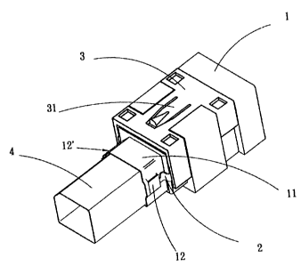
FIG. 1 is a perspective view of the connector of the present invention;
FIG. 2 is an exploded view of the connector of the present invention;
FIG. 3 is a perspective view of the connector of the present invention,
showing a latch member coupled with a socket;
FIG. 4 is a side view of the connector of the present invention coupled with
a socket;
FIG. 5 is a top view of the connector of the present invention coupled with
a socket;
FIG. 6 is a front view of the connector of the present invention coupled
with a socket;
FIG. 7A is a schematic view of the connector of the present invention
disengaging from a socket; and
FIG. 7B is a schematic view of the connector of the present invention
detached from a socket.
DETAILED DESCRIPTION OF THE PREFERRED EMBODIMENT
Referring to FIGS. I and 2, the connector according to the present
invention includes at least a body 1, a latch member 2, a sleeve member 3
and a socket 4. The body 1 has a coupling section 11 at a front end thereof.
The coupling section i 1 has two wedge slots 12 and 12' formed at two lateral
sides thereof, a stepwise indent section 15 behind the wedge slots 12 and 12',
a recessed section 13 formed at the top of the coupling section 11, and a stub
14 located at the rear end of the recessed section 13.
The latch member 2 has an elongated lever 21 which has at one end thereof
2


CA 02369387 2002-O1-25
two symmetrical hook arms 22 and 22' extended downwards at the two sides
of the lever 21, an elastic tongue 23 located at the top of the Iever 21, and
a
bore 24 formed at the rear end of the lever 21. The bore 24 is aligned and
engageable with the stub 14. The hook arms 22 and 22' have respectively a
front slant tip 221 and 221', and a latch edge 222 and 222' opposite to the
slant tip 221 and 221' .
The sleeve member 3 is substantially formed in a H shape for mating
against the recess section 13 and has four legs 32 bent downwards. It has a
press lever 31 located at the top side thereof. Two front legs 32 have
l0 respectively a snap lug 33 formed at the bottom end of the inner side walls
thereof.
The socket 4 has two side stubs 41 formed at two lateral sides thereof. To
assemble the connector of the present invention, the latch member 2 is
disposed over the body 1 with the bore 24 engaging with the stub 14 and the
Iever 21 disposed in the recessed section 13, and the hook arms 22 and 22'
engaging the wedge slots 12 and 12' . Then, the sleeve member 3 is disposed
in the recessed section 13 to clamp the legs 32 over two sides of the body 1
with the lugs 33 clipped the indented section 15 thereby enabling the latch
member 2 to be engaged securely in the recessed section 13.
Referring to FIGS. 3 through 6, in order to engage the coupling section 11
of the body 1 with the socket 4, the slant tip 221 and 221' will enable the
hook arms 22 and 22' to move downwards to pass over the side stubs 41, and
the latch member 2 will also be moved downwards to force the compressed
elastic tongue 23 to press against the top side of the recessed section I 3.
This
constitutes an engagement state in which the connector body 1 is engaged
securely with the socket 4 with no risk of breaking away.
Referring to FIGS. 7A and 7B, for disengaging the connector from the
socket, the press lever 3I is pressed downwards which also pushes the latch
3


CA 02369387 2002-O1-25
member 2 downwards, so that the latch edges 222 and 222' are moved away
from the side stubs 4I. The connector thus may be moved away from the
socket 4. After the connector is detached from the socket, absence of the
pressing force from the press lever 31 allows the restoration force of the
elastic tongue 23 to raise the latch member 2 to its initial position for use
next
time.
While the preferred embodiment of the present invention has been set forth
for purpose of disclosure, modifications of the disclosed embodiment of the
invention as well as other embodiments thereof may occur to those skilled in
the art. Accordingly, the appended claims are intended to cover all
embodiments which do not depart from the spirit and scope of the present
invention.

Dessin représentatif
Une figure unique qui représente un dessin illustrant l'invention.
États administratifs

Pour une meilleure compréhension de l'état de la demande ou brevet qui figure sur cette page, la rubrique Mise en garde , et les descriptions de Brevet , États administratifs , Taxes périodiques et Historique des paiements devraient être consultées.

États administratifs

Titre Date
Date de délivrance prévu 2004-11-09
(22) Dépôt 2002-01-25
Requête d'examen 2002-01-25
(41) Mise à la disponibilité du public 2003-07-25
(45) Délivré 2004-11-09
Réputé périmé 2010-01-25

Historique d'abandonnement

Il n'y a pas d'historique d'abandonnement

Historique des paiements

Type de taxes Anniversaire Échéance Montant payé Date payée
Requête d'examen 200,00 $ 2002-01-25
Enregistrement de documents 100,00 $ 2002-01-25
Le dépôt d'une demande de brevet 150,00 $ 2002-01-25
Taxe de maintien en état - Demande - nouvelle loi 2 2004-01-26 50,00 $ 2003-12-23
Taxe finale 150,00 $ 2004-08-30
Taxe de maintien en état - Demande - nouvelle loi 3 2005-01-25 50,00 $ 2004-10-01
Taxe de maintien en état - brevet - nouvelle loi 4 2006-01-25 50,00 $ 2005-12-14
Taxe de maintien en état - brevet - nouvelle loi 5 2007-01-25 100,00 $ 2006-12-21
Taxe de maintien en état - brevet - nouvelle loi 6 2008-01-25 100,00 $ 2008-01-18
Titulaires au dossier

Les titulaires actuels et antérieures au dossier sont affichés en ordre alphabétique.

Titulaires actuels au dossier
WIESON ELECTRONIC CO., LTD.
Titulaires antérieures au dossier
CHEN, MARK
HSU, IVAN
Les propriétaires antérieurs qui ne figurent pas dans la liste des « Propriétaires au dossier » apparaîtront dans d'autres documents au dossier.
Documents

Pour visionner les fichiers sélectionnés, entrer le code reCAPTCHA :


Pour visualiser une image, cliquer sur un lien dans la colonne description du document. Pour télécharger l'image (les images), cliquer l'une ou plusieurs cases à cocher dans la première colonne et ensuite cliquer sur le bouton "Télécharger sélection en format PDF (archive Zip)" ou le bouton "Télécharger sélection (en un fichier PDF fusionné)".

Liste des documents de brevet publiés et non publiés sur la BDBC .

Si vous avez des difficultés à accéder au contenu, veuillez communiquer avec le Centre de services à la clientèle au 1-866-997-1936, ou envoyer un courriel au Centre de service à la clientèle de l'OPIC.


Description du
Document 
Date
(yyyy-mm-dd) 
Nombre de pages   Taille de l'image (Ko) 
Page couverture 2004-10-15 1 36
Abrégé 2002-01-25 1 25
Dessins représentatifs 2002-06-06 1 8
Page couverture 2003-07-04 1 36
Description 2002-01-25 4 170
Revendications 2002-01-25 2 65
Dessins 2002-01-25 5 82
Correspondance 2004-08-30 1 32
Cession 2002-01-25 6 203