Note : Les descriptions sont présentées dans la langue officielle dans laquelle elles ont été soumises.
CA 02372258 2008-01-18
SINGLE SHOT MENISCAL REPAIR DEVICE
BACKGROUND
1. Technical Field
The present disclosure relates generally to the field of endoscopic
surgical devices. More specifically, the present disclosure relates to an
endoscopic
fastener applying device for repairing torn tissue such as torn meniscus
tissue.
__..:... _..:.. . .._..__:.:. .
2. Background" of Related 'Art
One known technique for repairing torn meniscus tissue involves the
use of a pair of surgical needles which are inserted through cannuli into the
knee on
opposite sides of a meniscal tear. The ends of the needles include a length of
suture
material which is pushed down through the cannuli and across the tear. An
incision
is made in the skin at the point where the needle exits the knee joint so that
the
leading end of each needle may be grasped and pulled through the joint. The
ends
of the sutures are then grasped after the needles are removed from the suture
ends
and the suture is then tied so that a horizontal suture is created in the
meniscus.
This procedure is repeated for placemeiit of as many sutures as necessary to
repair
the meniscus tear. As is apparent, this process is both time consuming and
difficult
to effect.
A subsequent improvement over this procedure is outlined in U.S. Patent
No. 5,002,562. In this procedure, a barbed clip and an instrument for applying
the clip
are utilized. The instrument has a pair of opposed arcuate jaws which are
shaped to
hold a complementary-shaped curved surgical clip therebetween, such that the
barbs of
the clip are retained within notches in the jaws until the clip is inserted.
The legs of the
clip are joined by a flexible suture material. The jaws are biased in a
normally open
position, and as the jaws are pushed into the tissue, the jaws are scissored
or closed
together until they preferably overlap to move the legs of the clip together
until they
cross. The jaws are then reopened and backed out of the tissue, with the barbs
of the
clip retaining the clip in position in the tissue.
CA 02372258 2008-01-18
A further reinfinement to meniscal repair is illustrated in U.S. Patent No.
5,997,552. This patent details a meniscal fastener applying device which
applies
fasteners sequentially from a longitudinally extending magazine. An advancing
mechanism is operatively associated with an elongated body portion of the
device for
sequentially advancing surgical fasteners from a fastener supply to a firing
position in
alignment with a firing mechanism. The fastener includes a pair of anchor
members
whose proximal-most ends are connected by a suture material offset from the
central
longitudinal axis thereof. Because of the parallel over-under orientation of
the firing
mechanism and the longitudinally extending fastener magazine, the elongated
body
portion of the device requires a substantial cross-sectional area and
necessarily requires
a correspondingly wide distension of the knee joint to access the meniscal
tissue to be
repaired.
SUMMARY
In accordance with an embodiment of the present invention there is
provided a surgical fastener apparatus for applying surgical fasteners of
general U-
shape to body tissue, comprising: a housing including a handle portion and a
trigger
mechanism; an elongated body portion extending from the housing and defining a
longitudinal axis, the elongated body portion having a generally annular cross-
sectional
area substantially along the length thereof and defining a longitudinal
pathway therein;
a firing mechanism operatively connected to the housing and including a pair
of
substantially parallel push rods positioned within the longitudinal pathway of
the
elongated body portion, the firing mechanism being capable of driving a
surgical
fastener inserted in a distal end portion of the elongated body portion to the
body tissue
in response to operation of the trigger mechanism; and a manually operable
member
operatively connected to the elongated body portion and engageable by a user,
the
manually operable member adapted for movement relative to the housing to cause
corresponding rotational movement of the elongated body portion about the
longitudinal axis.
In accordance with another embodiment of the present invention there is
provided a surgical apparatus, which comprises: a housing dimensioned for
engagement by the hand of a user; an elongated body portion extending from the
housing, the elongated body portion defining a central longitudinal axis and
having
2
CA 02372258 2008-01-18
proxiinal and distal ends; a single fastener mounted adjacent the distal end
of the
elongated body portion, the fastener having pair of anchor legs interconnected
by a
flexible member; at least one push rod disposed within the elongated body
portion, the
one push rod adapted for longitudinal movement to deploy the fastener into
tissue; and
a trigger mounted to the housing and operatively connected to the one push
rod, the
trigger movable relative to the housing to cause corresponding movement of the
one
push rod, the trigger being operatively engageable with a resilient spring
disposed
within the housing wherein movement of the trigger a first distance at least
partially
compresses the spring and movement of the trigger a second distance causes
release of
the resilient spring and consequent return of the resilient spring to an
uncompressed
condition, to thereby operatively engage the one push rod and effect
longitudinal
movement thereof and deployment of the fastener into the tissue.
Yet another embodiment of the present invention provides a surgical apparatus,
which comprises: a housing dimensioned for engagement by the hand of a user;
an
elongated body portion extending from the housing, the elongated body portion
defining a central longitudinal axis and having proximal and distal ends, the
elongated
body portion having an offset portion adjacent the distal end thereof, the
offset portion
being arranged in oblique relation relative to the longitudinal axis; a single
fastener
mounted adjacent the distal end of the elongated body portion, the fastener
having a
pair of anchor legs interconnected by a flexible member; at least one push rod
disposed
within the elongated body portion, the one push rod adapted for longitudinal
movement
to deploy the fastener into tissue; and a trigger mounted to the housing and
operatively
connected to the one push rod, the trigger movable relative to the housing to
cause
corresponding movement of the one push rod.
A still further embodiment of the present invention provides the surgical
apparatus, which comprises: a housing dimensioned for engageinent by the hand
of a
user; an elongated body portion extending from the housing, the elongated body
portion
defining a central longitudinal axis and having proximal and distal ends, the
elongated
body portion having a penetrating member in general parallel relation to the
central
longitudinal axis, the penetrating member adapted to penetrate tissue to
facilitate
positioning of the elongated body portion relative to the tissue; a single
fastener
mounted adjacent the distal end of the elongated body portion, the fastener
having a
pair of anchor legs interconnected by a flexible member; at least one push rod
disposed
2a
CA 02372258 2008-01-18
within the elongated body poi-tion, the one push rod adapted for longitudinal
movement
to deploy the fastener into tissue; and a trigger mounted to the housing and
operatively
connected to the one push rod, the trigger movable relative to the housing to
cause
corresponding movement of the one push rod.
According to preferred embodiments, a single shot meniscal repair
device is provided which incorporates a minimally sized elongate body portion
configured to hold a single fastener adjacent a distal end thereof. The
elongate body
portion is part of a disposable loading unit structure which facilitates up to
360 rotation
about the longitudinal axis of the elongate body portion. In an alternate
embodiment, at
least a distal poi-tion of the elongate body portion is angled off axis to
enhance the
versatility of the device. The fastener applied by the device includes a pair
of anchor
members interconnected by a flexible material. The flexible material extends
from a
respective side of the anchor members, thus maintaining the proximal ends
thereof
clear to receive the full driving force from the firing assembly without the
risk of
damaging the connecting flexible material.
30
2b
CA 02372258 2001-12-07
WO 01/76456 PCT/US01/11611
BRIEF DESCRIPTION OF THE DRAWINGS
Various embodiments are described herein with reference to the
drawings, wherein:
FIG. 1 is a perspective view of one embodiment of the meniscal
repair device of the present disclosure;
FIG. 2 is a perspective view with parts separated of the meniscal
repair device of FIG. 1;
FIG. 3 is a perspective view sliowing the elongate body portion of the
meniscal repair device of FIG. 1;
FIG. 4 is a perspective view showing a 10 upsweep version of the
elongate body portion in accordance with one embodiment of the meniscal repair
device of the present disclosure;
FIG. 5 is a perspective view showing a 30 left/right bend version of
the elongate body portion in accordance with one embodiment of the meniscal
repair
device of the present disclosure; and
FIG. 6 is an enlarged perspective view showing.the fastener used in
the meniscal repair device of the present disclosure.
DETAILED DESCRIPTION OF PREFERRED EMBODIMENTS
Preferred embodiments of the presently disclosed stapler will now be
described in detail with reference to the drawings, in which like reference
numerals
designate identical or corresponding elements in each of the several views.
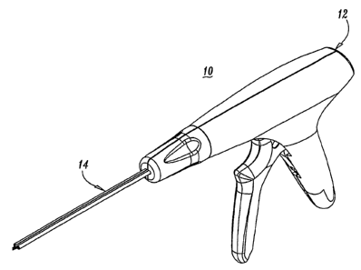
Referring now to the drawings, FIG. 1 illustrates a first embodiment
of the fastener applying device shown generally as 10. Briefly, the staple
applying
device 10 includes a housing assembly 12 and a disposable loading unit 13
having an
elongated body portion 14 defining a longitudinal axis thereof. The elongated
body
portion 14 is preferably minimally dimensioned for arthroscopic utilization.
-3-
CA 02372258 2008-01-18
The components of the housing assembly 12 of the fastener applying
device 10 are best illustrated in FIG. 2. The housing assembly 12 includes a
housing
formed from molded housing half-sections 12a and 12b within which the
components
of the housing assembly 12 are positioned. The housing assembly 12 further
includes a
movable handle 22 and a stationary handle 24 which is formed from portions
extending
from housing half-sections 12a and l2b to form a pistol grip type handle.
Movable
handle 22 and stationary handle 24 facilitate remote actuation of a firing
assembly
including a firing plate 52 through the elongated body portion 14 to effect
the ejection
of a surgical fastener 30 from the distal end of the elongated body portion
14.
The movable handle member 22 is secured to the housing half
sections 12a and 12b by a pin 26 which permits rotation of the movable handle
22
relative to the stationary handle 24. A handle spring 28 is connected to the
movable
handle 22 by a pin 20 and to the housing 12 by a pin 34 so as to bias the
movable
handle 22 to an open position. The pin 20 is dimensioned to be received in
openings 21 formed in the movable handle 22.
An actuation arm member 32 is operatively associated with the
movable handle 22 and is pivotably corinected to the lower end of the
stationary
handle 24 by pin 34. A cam roller member 36 is rotatably mounted to the
movable
handle 22 and is configured to engage and move along a cam path surface 38
defmed on the actuation arm member 32 by the proximal facing outer surface
thereof. Engagement between the cam roller member 36 and the cam path surface
38 effectuates counter-clockwise rotation of the actuation arm member 32 about
pin
34 when the instrument is viewed from the right side, as shown in FIG. 2.
A latch member 40 is pivotably mounted to the top portion of the
actuation arm 32 by pivot members 41. The latch member 40 is dimensioned and
configured to detachably engage with a firing block 42 which is slidably
mounted in
the housing assembly 12. An engaging spring 46 connects the latch member 40 to
-4-
CA 02372258 2001-12-07
WO 01/76456 PCT/US01/11611
the actuation arm member 32 so as to pivot the latch member 40 about pivot
members 41 into engagement with the firing block 42. The latch member 40 has a
hook member 49 pivotable about pivot members 41 into engagement with a post 51
formed on the firing block 42.
As mentioned above, the firing block 42 is slidably mounted in the
housing assembly 12 and is movable in response to corresponding movement of
the
movable handle member 22. A mounting projection 50 extends from the end of the
firing block 42 and is dimensioned and configured so as to detachably engage
with
the proximal end 53 of firing plate 52.
A bearing washer 60 is received about and engages a central portion
55 of the firing block 42, and a snap washer 62 is fixedly attached to the
distal end
portion 42b of the firing block 42 to capture and retain a compression spring
58
therebetween. Upon actuation of the handle assembly, the compression spring 58
is
compressed between bearing washer 60 and snap washer 62 creating a force
urging
firing block 42 in a distal direction. Additional washers 65 for sealing,
spacing and
fitting purposes may be operatively associated with the distal end portion 42b
of the
firing block 42.
As described above, proximal movement of the movable handle 22
causes the cam roller 36 to engage the cam path surface 38 and rotate
actuating arm
member 32 and latch member 40 in a counter-clockwise direction When viewing
the
instrument from the right side, as shown in FIG. 2. The hook member 49 formed
on the latch member 40 engages post 51 formed on the firing block 42 to slide
the
firing block 42 proximally as latch member 40 and actuating cam member 32
rotate
counter-clockwise in response to proximal movement of handle 22. The proximal
movement of the firing block 42 causes bearing washer 60 to engage a bearing
surface 64 defined on the interior of the housing assembly 12 (See FIG. 2). As
the
firing block 42 is moved proximally, the compression spring 58 is compressed
between the washer 60 and the snap washer 62 creating a force urging firing
block
-5-
CA 02372258 2001-12-07
WO 01/76456 PCT/US01/11611
42 in a distal direction. After the spring 58 has been compressed, the latch
member
40 contacts a camming wall 66 defined in the proximal end portion of the
housing
assenibly 12 which, in turn, causes the latch member 40 to pivot clockwise
about
members 41 to disengage hook member 49 from post 51. The release of stored
energy from the compression spring 58 urges the firing block 42 to move
distally
resulting in corresponding distal movement of the firing plate 52.
As firing plate 52 moves distally, it engages rod holder 70 and
continues in combined distal movement to drive parallel push rods 72 distally
to
engage and eject fastener 30. Upon completion of the firing motion, handle 22
is
relaxed thus withdrawing firing block 42 and firing plate 52 proximally
relative to
rod holder 70 and push rods 72.
The disposable loading unit 13 includes rotational housing 80 formed
of housing half-sections 80a and 80b. Mounted within housing 80 are the firing
plate 52 and rod holder 70. The elongate body portion 14 is mounted to housing
80
by pins 82 and extends distally therefrom. Push rods 72 are attached to rod
holder
70 and are disposed within the elongate body portion 14. A new fastener 30 is
disposed adjacent a distal end 74 of elongate body portion 14.
Once firing is completed, the expended disposable loading unit 13 is
rotated relative to the housing 12 effectively disengaging firing plate 52
from
mounting projection 50 on firing block 42. The expended disposable loading
unit is
then withdrawn distally from housing 12 and discarded. A new disposable
loading
unit is inserted into housing 12 and rotated to engage mounting projection 50
with
proximal end 53 of mounting plate 52. The device 10 is then ready for
subsequent
firing.
Referring to FIG. 3, the elongate body portion 14 is illustrated in a
series of views. Rods 72 are configured and dimensioned to travel coaxially
within
the elongate body portion 14. The cross-sectional dimensions of elongate body
-6-
CA 02372258 2001-12-07
WO 01/76456 PCT/US01/11611
portion 14 are minimized to more easily facilitate introduction to the
operative site.
A locating barb 76 can be positioned at a distal end of the elongate body
portion 14
to assist in stabilizing the device at the firing point.
FIGS. 4 and 5 illustrate alternate embodiments of elongate body
portion 14 wherein the distal portion is upswept by 10 (FIG. 4) or bent
left/xight
by 30 (FIG. 5). Elongate body portions shown in FIGS. 4 and 5 are otherwise
substantially the same as shown in FIG. 3.
A lastener 30 for use in device 10 is illustrated in FIG. 6 in a series
of views. Fastener 30 includes a pair of anchor members 90 linked by a
flexible
member 92. Preferably, the entire fastener is formed of bioabsorbable material
which resorbs at an appropriate rate to facilitate healing of a tear in the
meniscus.
Each of the anchors 90 has a tapered distal end 94 and a planar proximal end
96.
Flexible member 92 extends between adjacent side surfaces 98 of anchors 90
spaced
between the proximal end 96 and the distal end 94 thereof. This configuration
protects the flexible member 92 from inadvertent damage caused by the rods 72.
Each anchor member 90 is further provided with a series of radial projections
100
on its periphery to inhibit withdrawal of the anchor members 90 once they have
been positioned within body tissue.
-7-