Note : Les descriptions sont présentées dans la langue officielle dans laquelle elles ont été soumises.
CA 02377470 2001-12-17
WO 01/04563 PCT/AUOO/00824
-1-
PRIMER CASING AND METHOD OF CHARGING A BLASTHOLE
The present invention relates to a primer casing and to a method of charging a
blasthole.
Some mining methods involve drilling long blastholes into rock from within a
development drive, i.e. a tunnel. These blastholes may be up to 50 metres in
length and
vary in diameter. The blastholes typically radiate from the development drive
vertically,
horizontally and at any angle therebetween. The blastholes are filled with
explosives
which, when detonated, break the surrounding rock. In practice, each blasthole
contains a
bulk explosive and an initiating explosive. The bulk explosive may be granular
in nature,
such as ANFO, or it may be an emulsion explosive. The initiating explosive
typically
consists of a primer and is responsible for detonation of the bulk explosive.
The primer is
typically a solid packaged explosive or an emulsion-based explosive in the
form of a
cartridge. When charging the blasthole the primer is positioned at a selected
location or
locations and this is done by pushing the primer into position by use of a
loading hose.
The loading hose is also used to deliver the bulk explosive to the blasthole
adjacent to the
primer.
Positioning of a primer at a desired location within a blasthole may be
difficult due to
obstructions and/or discontinuities within the blasthole. For instance, when
an explosion
takes place in the vicinity of an uncharged blasthole, the blasthole walls are
subjected to
stresses. This can lead to distortion of the walls resulting in sections of
the blasthole being
non-aligned or off-set. In this case, it may be difficult or even impossible
to push the
primer along the blasthole to the desired location. This is because the primer
is usually in
the form of a cylindrical cartridge having a leading surface which has a flat
top and an
acute edge. This kind of shape means that the primer is prone to snagging on
obstructions
and/or discontinuities in the blasthole as the primer is pushed into place. In
this case the
primer may not be positioned correctly and re-drilling of the blasthole may be
required.
This is time-consuming and uneconomic.
It is also important that the primer is retained in the blasthole in the
desired position, and
unwanted movement of the primer, for instance due to the effect of gravity or
an
CA 02377470 2007-07-20
-2-
unauthorised attempt to withdraw the primer, should preferably be minimised or
avoided.
In the past, "spiders" in the form of a circular band having outwardly
projecting rigid legs
have been used for retaining a primer in the desired position in a blasthole.
However, such
"spiders" have generally been provided as separate articles which must be
fixed to a primer
at the blasthole or mine site. As well as this being time-consuming, the
packaging and
transportation of such "spiders" is inefficient due to their irregular shape
and rigidity of the
projecting legs.
The present invention seeks to address these problems by providing a primer
casing which
is adapted to receive a primer and to be positioned in a blasthole even when
the blasthole
contains obstructions and/or discontinuities. Furthermore, the primer casing
of the present
invention enables the primer to be retained at a desired location within the
blasthole,
irrespective of the orientation of the blasthole or any unauthorised attempt
to withdraw the
primer. The primer casing thus permits improved loading of a blasthole.
Accordingly, the present invention provides a primer casing comprising a
sleeve portion
and a leading portion as integral components of a unitary piece, wherein the
sleeve portion
is adapted to receive a primer and comprises a blasthole engagement means as
an integral
part of the sleeve portion, and wherein the leading portion comprises a nose
cone which is
provided at one end and as an extension of the sleeve portion.
The sleeve portion of the primer casing is adapted to receive a primer and the
exact
construction of the sleeve portion will depend upon the shape and
configuration of the
primer. Typically however the primer is in the form of a cylindrical cartridge
and the
sleeve portion defines a cylindrical passage (or cavity) into which the primer
cartridge may
be slidably inserted. Other configurations for the sleeve portion are of
course possible.
The passage of the sleeve portion is usually sized relative to the primer
cartridge so that
the cartridge is frictionally retained in the cavity or passage. However, in a
preferred
embodiment the primer casing is provided with means for retaining the primer
within
passage of the primer casing. The retaining means may be a tab, preferably a
centre-
hinged (reversible) tab, which is integral with the sleeve portion of the
casing and which
may be extended into the cavity after insertion of the primer to engage the
primer body
CA 02377470 2001-12-17 PCT/Act00/00824
Received' 14 May 2001
P'OPERUcc6PECIFICAt1ONSPRIMER CASING 30 1 Odoc=I010401
-3-
(which may be suitably adapted to be so-engaged) or to support the end of the
primer. The
effect is that the primer is retained in position within the sleeve portion of
the primer
casing.
The leading portion of the primer casing comprises a nose cone. The nose cone
is
provided at one end, and as an extension, of the sleeve portion of the casing.
The nose
cone is less prone to snagging on obstructions and/or discontinuities than a
flat-ended
construction. Typically, the apex of the nose cone is rounded. The nose cone
is typically
deflected by obstructions and/or discontinuities rather than being snagged on
them. Thus,
the nose cone can assist in guiding the primer casing past and around
obstructions and/or
discontinuities in the blasthole.
In a preferred embodiment, the nose cone is hollow so that when, in place, the
end of the
primer does not contact the inside surface of the cone. In this embodirnent
the nose cone is
able to absorb shock which might otherwise be communicated to the primer when
the
primer casing impacts against an obstruction and/or discontinuity in, or the
end of, a
blasthole during positioning of the primer casing in the blasthole. This helps
to avoid
damage to the primer. Use of a hollow nose cone also provides a saving in
materials cost.
The blasthole engagement means usually takes the form of a projection from the
sleeve
portion of the primer casing. In a preferred embodiment of the invention the
blasthole
engagement means is movable between a retracted position and a blasthole
engagement
position.
In the retracted position the blasthole engagement means may abut t:he sleeve
portion of
the casing. For example, in the retracted position the blasthole engagement
means may be
integral with the casing and attached thereto by a flexible hinge which
enables the
blasthole engagement means to be movable between the two positions.
Alternatively, in
the retracted position, the blasthole engagement means may be held adjacent to
or within
the casing, for example usin- retaininQ cord, wire or band. With the blasthole
enaagement
means in the retracted position the primer casing lends itself to bc;ing
packed and
transported in an economic manner.
AMENDED SF1EET
tPEAlAU
CA 02377470 2001-12-17
WO 01/04563 PCT/AUOO/00824
-4-
In the blasthole engagement position, the projection is typically inclined
outwardly relative
to the primer casing and rearwardly relative to the leading portion. The
projection is
relatively rigid so that when it engages the wall of a blasthole little
deflection of the
projection takes place. If the projection does not have sufficient rigidity,
it will not be able
to function to maintain the primer casing in a desired position in a blasthole
when the
casing is subjected to forces which would otherwise cause withdrawal of the
casing along
and from the blasthole. Generally the primer casing is provided with at least
two and
preferably three or four such projections. The primer casing may comprise more
than one
array of multiple projections. When more than one projection is used, the
projections will
typically be of equal length. Usually, the projection comprises a leg portion.
The end of each projection may be provided with a wall engagement means which
enables
the projection to run over the surface of a blasthole wall as the primer
casing is inserted
into the blasthole, but which is capable of engaging the wall surface to
assist in preventing
unintentional withdrawal/movement of the primer casing. The wall engagement
means
may be a spike or prong which is capable of engaging the surface of a
blasthole wall.
The blasthole engagement means may be moved from the retracted position to the
blasthole engagement position at the mine site or blasthole so as to enable
benefit to be
derived from the ability to economically pack and transport the primer
casings. Whilst the
blasthole engagement means may be manually moved between retracted and
blasthole
engagement positions, it is preferred that insertion of the primer into the
primer casing
causes the blasthole engagement means to be so-moved. This may be possible for
example
when the blasthole engagement means is integral with the primer casing and a
portion of
the blasthole engagement means is provided within the sleeve portion of the
primer casing
which is adapted to receive the primer. In this arrangement insertion of the
primer into the
sleeve portion forces the blasthole engagement means outwardly and into the
blasthole
engagement position.
The blasthole engagement means may be integral with the primer casing, and
preferably
forms part of the sleeve portion thereof. In a preferred embodiment of the
invention the
sleeve portion and leading portion are integral components of a unitary piece.
In this
CA 02377470 2001-12-17
WO 01/04563 PCT/AUOO/00824
-5-
embodiment, the entire assembly may be formed by injection moulding a plastics
material
using a single mould. Any plastics material may be used provided it imparts a
desired
level of rigidity to the casing. For instance, in order to prevent snagging,
the nose cone of
the casing should be sufficiently rigid to avoid undue deformation. If the
nose cone is too
easily deformed, it will not function in guiding the casing around or past
obstructions
and/or discontinuities in a blasthole wall. As described above, the blasthole
engagement
means should also exhibit a degree of rigidity in order to fulfil the desired
function. As
plastics which may be used, mention may be made of polyethylenes and
polypropylenes.
The primer is usually in the form of a cylindrical cartridge having a rigid
body. The
cartridge is typically made of cardboard.
In a preferred embodiment of the present invention, in use a primer is
inserted into the
primer casing and this causes the blasthole engagement means to move from the
retracted
position to the blasthole engagement position. The primer casing may then be
inserted into
a blasthole for initiation of an explosives charge. The blasthole engagement
means enables
the primer casing to be retained in position with the blasthole from the time
of loading
through to detonation. This is achieved by interaction between blasthole
engagement
means and the walls of the blasthole so as to substantially retain the
position of the primer
casing, and thus the primer, within the blasthole.
The primer is initiated by a signal tube. Conventional initiation means may be
used. Thus,
electric, non-electric or electronic initiation means may be employed.
Usually the primer casing may be loaded into a blasthole by using a loading
hose. The end
of the loading hose typically makes contact with the end of the primer casing
remote from
the nose cone of the leading portion. Problems can occur when the end of the
loading hose
and primer casing do not sit coaxially together when the primer casing is
pushed into the
blasthole. In this situation the loading hose may be displaced to one side and
its leading
edge may snag on the blasthole wall. To avoid this, in a preferred embodiment
the primer
casing is adapted to receive the end of a loading hose. This helps to prevent
displacement
of the loading hose from the desired point of contact with the primer casing.
Thus, the
CA 02377470 2001-12-17
WO 01/04563 PCT/AUOO/00824
-6-
primer casing may preferably further comprise a loading hose engaging means
such as a
sleeve for receiving the primer. The loading hose engagement means may be an
extension
of the sleeve portion of the primer casing.
In one embodiment, the sleeve for engaging the end of the loading hose has an
internal
dimension slightly greater than the external dimension of the hose. The
difference in
dimension should be sufficient to accommodate a signal tube running from the
end of the
primer without damage to or abrasion of the tube. In this embodiment it is
also preferred
that the primer casing includes means for preventing contact between the end
of the primer
which is contained by the primer casing and the end of the loading hose. The
primer
casing may therefore include a tab (or tabs) which projects into the sleeve
portion of the
primer casing. To facilitate insertion of the primer it is preferred that the
tab may be
moved into a position in which it projects into the sleeve portion after the
primer has been
inserted into the casing. In a preferred embodiment the primer retaining means
described
above also serves to prevent contact between the primer and the loading hose.
The loading hose serves to push the primer casing into the desired location
within the
blasthole. Bulk explosive is then pumped through the loading hose into the
blasthole. It is
desired that the bulk explosive is in intimate contact with the primer and
preferably the
primer is surrounded by bulk explosive. To this end the primer casing may
include a
number of apertures to enable bulk explosive to contact the primer. Preferably
the sleeve
portion include such cavities. The hose, when discharging bulk explosive, will
separate
from the primer casing and fill the blasthole with bulk explosive whilst being
withdrawn
from the blasthole. Bulk explosive may flow into any spaces between the
blasthole wall
and the primer casing and may contact the primer directly via the apertures in
the casing.
In a further aspect, the primer casing may be provided with connector means
whereby a
plurality of primer casings may be interconnected such that the leading primer
casing
which is positioned by the hose drags subsequent primer casings into the
blasthole. The
separation distance between primer casings may be determined by the length of
the
interconnection between the primer casings. In a preferred configuration the
connector
means may be an aperture at either end of the primer casing such that the
primer casings
CA 02377470 2001-12-17
WO 01/04563 PCT/AUOO/00824
-7-
may be tied together with a length of signal tube, string, wire or the like.
This kind of
"train loading" is typically employed in larger diameter blastholes, for
instance 89mm or
102mm. This greatly speeds up the loading process. It is possible to employ
"train
loading" in smaller diameter blastholes, say 76mm, but only if the walls
thereof are
relatively smooth. In this type of loading bulk explosive is pumped into the
blasthole
continuously as the loading hose is withdrawn from the blasthole thereby
engulfing the
primers.
Loading problems tend to be associated with smaller rather than larger
diameter blastholes.
Thus, the present invention is typically employed in loading blastholes having
a diameter
of from about 70 to about 110mm, for instance 76mm, 89mm or 102mm in diameter.
In practice, the primer casing has an internal diameter of about 35mm. The
diameter of the
primer cartridge is slightly less than this. A primer casing of this internal
diameter is
typically used in conjunction with a loading hose having an external diameter
of about
28mm. In this case the signal tube (diameter typically 3mm) is easily
accommodated in
the gap between the loading hose and the primer casing, the clearance being
about 4mm.
If a larger diameter loading hose is used, for instance, 32mm diameter, there
signal tube
may still just be accommodated.
The present invention further provides a method of loading a blasthole which
comprises
inserting a primer into a primer casing as described herein and positioning
the primer
casing at a desired location in the blasthole. Usually, the primer casing is
positioned using
a loading hose. After positioning of the primer casing, the blasthole is
charged, usually via
the loading hose, with bulk explosive.
The present invention further provides a method of loading a blasthole wherein
a plurality
of primers are positioned, spaced apart, in a blasthole wherein said plurality
of primers are
interconnected such that the positioning of the first primer will cause the
subsequent
primers to be positioned within said blasthole.
CA 02377470 2001-12-17
WO 01/04563 PCT/AUOO/00824
-8-
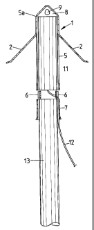
The present invention will now be further described with reference to the
accompanying
drawings. The drawings show primer casings which, when used with primers and
initiating systems have been proven to initiate bulk explosives reliably.
Figure 1 is a cut-
away representation of a primer casing (1) in accordance with the present
invention and
shows also a primer cartridge (11) prior to insertion therein. Figure 2 is a
cut away
representation of a primer casing (1) having a primer inserted therein as well
as the leading
end of a loading hose (13). Figure 2 shows a primer casing (1) including a
sleeve portion
(5) and a leading portion (5a). Figure 3 is a side view of a primer casing
(1). Figure 4 is a
cross section through A-A shown in Figure 3. In Figures 1 and 3 the blasthole
engagement means (2) are in the retracted position. In Figure 2 the blasthole
engagement
means are in the blasthole engagement position.
More specifically, Figure 1 shows a primer casing (1) having four blasthole
engagement
means (2) in the form of projecting legs, only three of which can be seen.
Each of the legs
incorporates an inward projection (3) formed by a bend in the leg. The legs
(4) are
integrally formed with the primer casing (1) and extend into the passage (4)
defined by the
sleeve portion (5). The passage (4) allows the legs to be retained within the
sleeve portion
(5) of the primer casing (1) for packaging and transportation. The legs are
urged outwards
on insertion of the primer (11) into the primer casing (1). The primer (11) is
retained
within the primer casing (1) in a position in which the blasthole engagement
means (2) are
urged outwards by the camming of inward projections (3) over the primer (11).
The
primer (11) is retained in this position by the over centre tabs (6) which may
be depressed
into a locking position as shown in Figure 2. The over centre tabs (6) also
act to prevent
the loading hose (13) from striking against the primer (11) and deforming the
signal tube
(12) which extends from the primer (11). The sleeve portion (5) extends to
form a hose
receiving sleeve (7). The top of the primer casing (1) includes a nose cone
(8) in which
there is provided apertures (9).
As illustrated in Figure 4 the over centre tabs (6) have flexible hinges, (6a,
6b and 6a). The
hinges (6a) allow the over centre tab to depressed inwardly and the central
hinge (6b)
permits the over centre tab to deform and stably retain a locked position.
CA 02377470 2001-12-17
WO 01/04563 PCT/AUOO/00824
-9-
An embodiment of the invention will now be described with reference to the
following
example.
Example
A series of blastholes (diameter 89mm and 102mm) were drilled in a formation.
The
formation was highly stressed and prone to movement. A number of blastholes
were
charged with bulk explosive and blasted. Surrounding uncharged blastholes were
thus
subjected to blast induced damage.
Attempts were made to load the uncharged blastholes with primer using a
mechanical hose
pusher. In one series of tests, attempts were made to load a cylindrical
primer cartridge to
which was attached a ring having leg-like blasthole engagements means (a
"spider" as
described herein). The leading end of the primer was flat and acute. In
another series of
tests, primer was inserted into a primer casing in accordance with the present
invention.
Severe difficulties were encountered in the first series of loading tests. The
primer became
snagged in the blasthole and could not be fed using the mechanical hose
pusher. In order
to advance the primer along the blasthole it became necessary to twist and
turn the loading
hose as well as repeatedly moving the primer backwards and forwards. This
manual
manipulation is very time consuming and uneconomic. In certain instances the
primer
could not be positioned correctly, even with manual manipulation of the
loading hose.
In contrast, no loading problems at all were encountered when using the primer
casing in
accordance with the present invention. The mechanical pusher was able to
achieve
insertion of the primer without difficulty, thereby avoiding the need for
manual
intervention.
Those skilled in the art will appreciate that the invention described herein
is susceptible to
variations and modifications other than those specifically described. It is to
be understood
CA 02377470 2001-12-17
WO 01/04563 PCT/AUOO/00824
-10-
that the invention includes all such variations and modifications which fall
within its spirit
and scope. The invention also includes all of the steps, features,
compositions and
compounds referred to or indicated in this specification, individually or
collectively, and
any and all combinations of any two or more of said steps or features.
Throughout this specification and the claims which follow, unless the context
requires
otherwise, the word "comprise", and variations such as "comprises" and
"comprising", will
be understood to imply the inclusion of a stated integer or step or group of
integers or steps
but not the exclusion of any other integer or step or group of integers or
steps.