Note : Les descriptions sont présentées dans la langue officielle dans laquelle elles ont été soumises.
CA 02377630 2001-12-18
WO 01/81235 PCT/1B01/00670
1
Description
A forklift truck with reduced turning radius
Technical Field
The present invention relates to a forklift truck with
reduced turning radius.
In particular, the invention relates to a four-wheeled
forklift truck with relatively reduced minimum turning radius.
Background Art
Conventional forklift trucks comprise a three- or four-
wheeled vehicle which may be electrically powered or driven by an
internal combustion engine, two horizontal, power-driven forks
which extend from the front of the vehicle and are used to lift
and lower loads of various kinds, and a rear counterweight to
counterbalance the front load.
These forklift trucks, irrespective of their lifting
capacities, come in different designs and have distinct
characteristics depending on the number of wheels and on whether
they have front or back wheel drive.
In forklift trucks with three wheels, two of the three
wheels are mounted at the front on a single axis of rotation,
while the third wheel is mounted at the back in a longitudinal
plane through the centre of the vehicle. Steering is always
applied to the back wheel while vehicle drive may be front or back
wheel.
In lift trucks where the back wheel is not only the
steerable wheel but also the drive wheel, the two front wheels are
free to turn about their axes and their direction and speed depend
on the steer angle of the back wheel. When the back wheel is at
full steering lock, that is to say, turned by 90 degrees, the
centre of rotation of the vehicle is located at the point where
the common axis of the front wheels intersects the longitudinal
central plane of the vehicle. This means the turning radius is
relatively small, with obvious advantages in terms of
manoeuvrability in confined spaces.
CA 02377630 2001-12-18
WO 01/81235 PCT/1B01/00670
2
In a lift truck of this kind, the transmission of torque to
the ground depends on the vertical load acting on the back wheel,
which is the drive wheel. When the truck is carrying a load on the
forks, which are at the front, the total vertical load on the back
wheel is reduced, thus reducing the grip of the back wheel. The
more slippery the ground (as when it is wet, for example) the more
this problem is felt.
Instead, if the back wheel is only a steerable wheel and
drive is at the front wheels, two different cases can be
distinguished: in one case, the front wheels are equipped with a
differential; in the other, the front wheels are independently
driven.
In the first case, as the back wheel steer angle gets
larger, the inside front wheel tends to slow down since it is
forced to cover a path whose curvature is smaller than that of the
path covered by the outside front wheel. When the maximum steer
angle is reached, the inside front wheel does not revolve at all.
At the same time, the vehicle's centre of rotation, which
lies on the common axis of the front wheels, can vary from an
infinitely distant lateral position, when the front wheels are
straight, to a limit position corresponding to the point where the
inside front wheel touches the ground when the front wheels are at
full steering lock.
It follows that in this case, the minimum turning radius is
relatively large.
in the second case, the front wheels are usually driven by
two electrical motors. The speed and direction of the wheels are
electronically controlled by a control unit in accordance with the
steer angle of the back wheel. Thus, when the back wheel is at
full steering lock, the control unit causes the inside drive wheel
to revolve at the same speed as the outside drive wheel but in the
opposite direction so as to prevent the wheels from slipping and
sliding. By so doing, the control unit advantageously enables the
vehicle to turn about a point where the common axis of the front
wheels intersects the longitudinal central plane of the vehicle.
This provides the same manoeuvrability as the back wheel drive
CA 02377630 2001-12-18
WO 01/81235 PCT/1B01/00670
3
truck described above but avoids the problem of reduced grip when
heavy loads are being carried.
A three-wheeled truck of this kind, despite its relatively
reduced turning radius and good ground grip, is relatively
unstable compared to a four-wheeled truck. As taught by prior art,
the vertical projection of the truck's centre of gravity must fall
within an area which, in the case of this type of truck, is
delimited by the triangle defined by the three wheels, otherwise
the truck will tip over. Clearly, such an area is smaller than the
corresponding rectangular or trapezoidal area of a four-wheeled
truck.
In conventional four-wheeled lift trucks, drive is typically
on the front wheels, while steering is applied to the back wheels.
The rotation of each of the two back wheels is obviously
coordinated with the rotation of the other back wheel in such a
way as to prevent the wheels from slipping and sliding.
As in the case of three-wheel configurations, the front
wheels may be driven through a differential or independently of
each other as described above.
In the case of separate front wheel drive, the prior art
describes a steering mechanism which, when at full lock,
advantageously positions the vehicle's centre of rotation to the
point where the common axis of the front wheels intersects the
longitudinal central plane of the truck. This confers the same
manoeuvrability as three-wheeled trucks.
The back end of a forklift truck of this type, described by
the prior art, is quite complex and this not only complicates
truck assembly procedures but also makes maintenance of the
steering mechanism more difficult.
in particular, these forklift trucks have a counterweight-
rear axle-steering mechanism assembly where the positions of the
parts of the assembly relative to each other and of the assembly
itself relative to the frame are such as to hamper assembly and
maintenance operations.
CA 02377630 2008-03-07
WO 01/81235 PCT/IBO1/00670
4
Disclosure of the Invention
The present invention has for an object to provide an
improved forklift truck.
Accordingly, the invention provides a forklift truck with
reduced turning radius comprising: a frame; two front drive wheels
mounted on said frame in such a way that they rotate about a first
common axis of rotation transversal to a longitudinal central
plane of the truck; a rear axle; two back wheel mounting forks
supported by the axle in such a way that they rotate about
respective second axes which are substantially parallel to the
central plane; two steerable back wheels supported by the mounting
forks; steering means designed to coordinate the rotation of the
mounting forks about their respective second axes in such a way
that the centre of rotation of the forklift truck with the
steering at full lock is positioned at the point where the first
axis intersects the central plane; a rear counterweight; the
forklift truck being characterised in that the axle, the mounting
forks and the steering means form a unit which can be pre-
assembled and which is supported directly by a back end of the
frame; said back end also directly supporting the counterweight in
a position such that the pre-assembled unit is located between the
back end and the counterweight.
CA 02377630 2008-03-07
4a
In accordance with a first aspect of the present invention
there is provided a forklift truck with reduced turning
5-radius and having a longitudinal central plane and a centre
of rotation, the truck comprising
(i) a frame having a back end and a rear opening;
(ii) two front drive wheels mounted on said frame to be
rotatable about a f.irst common axis of rotation transversal
to-the central plane;
(iii) a rear axle.;,
(iv) two back wheel mounting forks supported by the axle to
be rotatable about respective second axes which are
substantially parallel to the central plane;
(v) two steerable back wheels each supported by one of the
mounting forks:,
(vi) steering means accessible through the rear opening of
.the frame and constructed and arranged to coordinate the
rotation of -the mounting forks about their respective second
axes_; and
(vii) a rear counterweight;
wherein
(a) the rear axle, the mounting forks and the steering means
are constructed and arranged to be pre-assembled to form a
unit to be supported directly by the back end of the frame;
(b) the back end directly supports the counterweight in a
position such -that the preassembled unit is located between
the back end and the counterweight; and
(c) the centre of rotation of the forklift truck with the
steering at full lock is positioned at a point where the
first common axis of rotation intersects the central plane..
CA 02377630 2008-03-07
4b
The invention will now be described with reference to
the accompanying drawings which illustrate a preferred
embodiment of it purely by way of example and in which::
Figure 1 is a schematic plan view of the forklift truck
with reduced turning radius according to the present
invention, shown with the steering at full lock;
Figure 2 is a schematic plan view of the forklift 'truck
according to the present invention in condition in which it
is travelling forward in a straight line;
Figure 3 is a rear view, with some parts in cross
section and some parts cut away for clarity, of an
embodiment of the forklift truck according to the present
1.5 invention;
Figure 4 is a plan view, with some parts in cross
section and some parts cut away for clarity, of the back end
of -the forklift truck illustrated in Figure 3;
CA 02377630 2001-12-18
WO 01/81235 PCT/1B01/00670
Figure 5 is an enlargement of Figure 4, with a dashed line
showing also the back end of the truck when the steering is at
full lock;
Figure 6 is a side sectional view, through line VI-VI and
5 with some parts cut away for clarity, of the structure illustrated
in Figure 4;
Figure 7 is a another rear view, with some parts in cross
section and some parts cut away for clarity, of an embodiment of
the forklift truck according to the present invention; and
Figure 8 is a cross section, through line VIII-VIII and with
some parts cut away for clarity, of the forklift truck illustrated
in Figure 7.
With reference to the accompanying drawings, the numeral 1
denotes in its entirety a four-wheeled forklift truck with reduced
turning radius.
The forklift truck 1 comprises a frame 2, two front drive
wheels 3a and 3b and two back steerable wheels 4a and 4b, and two
horizontal front forks (of known type and therefore not
illustrated) which are power-driven (in known manner and therefore
not illustrated) in such a way that they can lift and lower loads
of various kinds (not illustrated).
The front wheels 3a and 3b are driven independently of each
other (in known manner) by two respective transmission motors 41
and 42, and are mounted on the frame 2 in such a way that they
rotate about a first common fixed axis of rotation A transversal
to a longitudinal central plane M of the truck 1.
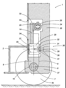
The hub 5 of each back wheel 4a, 4b has a substantially
horizontal axis of rotation 6 and is rotatably supported by a hub
mounting 7, which is squarely fitted to a lower end 8 of a branch
9 of a corresponding back wheel mounting fork 10.
The branch 9 is positioned' so that it faces the inner
surface of the hub 5 and constitutes a lower portion of the wheel
mounting fork 10, which is made in a single part and which, above
the branch 9 itself, has a central portion consisting of a
substantially cylindrical body 11.
The body 11 has a central axis of rotation 12, which is
aligned with the inner surface of the hub 5, substantially
CA 02377630 2001-12-18
WO 01/81235 PCT/1B01/00670
6
parallel to the plane M, and is rotatably mounted on a lateral end
13 of a rear axle 14, which is in turn mounted on the frame 2
transversely to the plane M and extends between the two back
wheels 4a and 4b over the two wheels 4a, 4b themselves. Looking in
more detail, the body 11 is mounted on the axle 14 on
corresponding bearings 15. The latter are positioned inside a
joint 16 that is relatively long in the direction of the axis 12
so as to confer on the body 11 relatively high resistance to the
shocks transmitted by the branch 9.
Above the body 11, the wheel mounting fork 10 also has an
upper portion consisting of a pin 17 which actuates the mounting
fork 10 itself.
The pin 17 has a grooved profile 18 by which its top end is
slotted to a lever 19 for actuating the wheel mounting fork 10.
The lever 19 is pivoted to an end 20 of a curved connecting
rod 21 which is shaped like a circular arc and whose opposite end
22 is pivoted to the operating end 23 of a hydraulic cylinder 24
(of known type) for steering the wheels 4a and 4b.
As shown in Figures 3 and 6, the steering cylinder 24 is
rigidly attached to an upper end portion 25 of the axle 14.
The specially shaped assembly formed by the steering
cylinder 24, the connecting rods 21 and the levers 19 constitutes
a steering device 26 designed to coordinate the angles of rotation
of the back wheel mounting forks 10 about their respective axes 12
in such a way as to prevent the wheels 4a and 4b from slipping or
sliding, and to enable the truck 1 to reach a full steering lock
configuration in which the centre of rotation C of the truck 1
coincides with the point where the axis A intersects the plane M.
Looking in more detail, this configuration, shown in Figure 1 and
by the dashed line in Figure 5, corresponds to a rotation of 74
degrees and 30 minutes by the outside back wheel 4a, 4b and of 105
degrees and 30 minutes by the inside back wheel 4a, 4b relative to
the configuration shown in Figure 2, where the wheels are
straight.
The axle 14 is made from sheet metal parts welded to each
other and is pivotally mounted on a rear. circular pin 27 of the
frame 2 extending in the longitudinal direction of the truck 1
CA 02377630 2001-12-18
WO 01/81235 PCT/1B01/00670
7
along a horizontal axis 28. Looking in more detail, the axle 14
has below it a parallelepiped-shaped block 29. In the latter there
is a circular through hole 30 by which the pin 27 is connected by
means of a plurality of bolts 31 arranged in a ring to a round
closing plate 32 placed on the side of the frame 2 opposite the
axle 14. The axle 14, the steering device 26, the mounting forks
and the wheels 4a and 4b can be pre-assembled to form a unit 33
that is easily fitted en bloc to the frame 2, which, as shown in
Figure 6, besides directly supporting said unit 33 through the pin
10 27, has, above the pin 27 itself, an opening 34 providing access
to the steering device 26 when maintenance is required. The truck
1 further comprises a counterweight 35 consisting of a single part
which closes the back end 36 of the truck 1. Looking in more
detail, with reference to Figure 7, the counterweight 35 extends
right across the width of the truck 1 and has a lower portion 37
which extends downwards between the wheels 4a and 4b and which is
suitably tapered towards the centre to allow the mounting forks 10
to rotate about the axes 12 under the action of the steering
device 26.
The counterweight 35 is supported directly by the frame 2
and is attached to the pin 27 by a bolt 38 located at the centre
of the ring of bolts 31. The counterweight 35 is mounted in a
position such that the unit 33 is placed between the pin 27 and
the counterweight 35 itself. In other terms, in this position, the
axle 14 and the steering device 26 are surrounded by the
counterweight 35 only on the sides (Figure 8), top and bottom
(Figure 6). This makes it possible to fit or remove the
counterweight 35 independently of the axle 14 and of the steering
device 26, while at the same time allowing access to the steering
device 26 through the opening 34 without removing the
counterweight 35. As mentioned above, the truck 1 is driven by the
front wheels 3a and 3b which are in turn driven independently of
each other by two respective transmission motors 41 and 42
controlled electronically in known manner by a control unit 43
which controls both their speed and direction in accordance with
the steer angles of the back wheels 4a and 4b. For this purpose,
the input of the control unit 43 is connected to a rotary type
CA 02377630 2001-12-18
WO 01/81235 PCT/1B01/00670
8
potentiometer 39 fitted above one of the two pins 17 (in this
particular case, as shown in Figures 1, 3, 5 and 8, above the pin
17 corresponding to the back right-hand wheel 4b), the
potentiometer spindle 40 being coaxial and attached to the pin 17
itself. The potentiometer 39 detects the steer angle of one of the
wheels 4a or 4b through the connection to the pin 17 and outputs a
signal to the control unit 43 which accordingly regulates the
speed and direction of rotation of the motors 41 and 42. The
potentiometer 39, being of the rotary type, permits accurate
detection of the steer angle of the back wheels 4a and 4b and thus
precise control of the transmission motors 41 and 42 that drive
the front wheels 3a and 3b.
CA 02377630 2001-12-18
WO 01/81235 PCT/1B01/00670
9
Key
1 FORKLIFT TRUCK
2 FRAME
3 FRONT WHEELS
4 BACK WHEELS
5 HUB
6 HUB AXIS
7 HUB MOUNTING
8 LOWER END OF 9
9 BRANCH OF 10
10 WHEEL MOUNTING FORK
11 CENTRAL PORTION (BODY) OF 10
12 AXIS OF 11
13 LATERAL END OF 14
14 AXLE
15 BEARINGS
16 JOINT
17 PIN OF 10
18 GROOVED PROFILE
19 LEVER FOR ACTUATING WHEEL MOUNTING FORK
20 END OF 21
21 CONNECTING ROD
22 END OF 21
23 END OF 24
24 STEERING CYLINDER
25 UPPER PORTION OF 14
26 STEERING DEVICE
27 FRAME PIN
28 AXIS OF 27
29 LOWER BLOCK OF 14
30 HOLE IN 29
31 BOLTS
32 ROUND PLATE
33 PRE-ASSEMBLED UNIT
34 FRAME OPENING
35 COUNTERWEIGHT
36 BACK END OF 1
CA 02377630 2001-12-18
WO 01/81235 PCT/1B01/00670
37 LOWER PORTION OF 35
38 BOLT
39 POTENTIOMETER
40 SPINDLE OF 39
5 41,42 TRANSMISSION MOTORS
43 CONTROL UNIT