Note : Les descriptions sont présentées dans la langue officielle dans laquelle elles ont été soumises.
CA 02378577 2002-01-31
WO 01/10495 PCT/US00/21100
1
Clip-On Access Port and Methods of Use
Field of the Invention
The present invention relates generally to a modular system for introducing
therapeutic or diagnostic devices, such as a blood filter, occluder,
atherectomy device,
stents, angiographic catheters, and pressure monitors to a vessel or cardiac
tissue. More
particularly, the system delivers the devices independently or in combination
through a
single incision on the vessel or cardiac tissue via one or more removably
attached access
ports and lumens.
Background of the Invention
During various cardiothoracic, pulmonary, and vascular surgeries, including
coronary artery bypass grafting, heart valve repair or replacement, atrial or
ventricular
septal defect repair, angioplasty, atherectomy, aneurysm repair, and pulmonary
thrombectomy, cannulation of a patient's vessel(s) are often required to
provide vascular
access for delivery of various diagnostic and therapeutic devices. In a
conventional
approach, separate incisions are needed for introduction of each medical
device. For
example, during coronary artery bypass grafting (CABG) surgeries,
cardiopulmonary
bypass is established by cannulation of the aorta to provide circulatory
isolation of the
heart and coronary blood vessels. Two incisions on the aorta may be required,
i.e., one for
insertion of the arterial cannula and another for insertion of a balloon
occluder to provide
coronary isolation from the peripheral vascular system. When cardiac arrest is
desired, a
third incision may be required on the aorta to introduce a catheter for
delivering
cardioplegic solution to the coronary arteries. Additional incisions may be
required for
insertion of other devices, such as a blood filter, pressure monitor, or
atherectomy device.
Once the incisions are made on the aorta, the devices often remain in the
aorta throughout
the entire procedure despite only being used intermittently, e.g., the
cardioplegia catheter.
Due to significant mortality and morbidity associated with conventional CABG
surgeries from the use of cardiopulmonary bypass for circulatory support and
the
CA 02378577 2007-12-04
2
traditional method of access by median sternotomy, minimally invasive concepts
recently have been adopted to make cardiothoracic procedures less invasive.
Minimally invasive alternatives include the minimally invasive direct CABG
procedure in which the operation is performed through minimal access
incisions,
eliminating cardiopulmonary bypass. The second alternative is to perform the
procedure through minimal access incisions, and cardiopulmonary support is
instituted through an extra thoracic approach, i.e., the port access approach.
The third
alternative is to perform the procedure on a beating heart which allows
greater access
for more extensive revascularization, i.e., the "off pump" sternotomy
approach. In any
of the minimally invasive alternatives, the space allowed for multiple
instrumentation
and device insertion is limited.
The disadvantages associated with the conventional or minimally invasive
approach are that (1) by having multiple devices inserted in the aorta, the
space
available for the surgeon to perform procedures is limited, and (2) the aorta
is
traumatized as a result of multiple incisions, which may result in aortic
dissection,
aortic wall hematoma, and/or embolization of calcium plaque from the aortic
wall.
The greater the aortic trauma, the higher the perioperative morbidity a
patient will
endure.
New devices or systems are therefore needed which provide access to a
patient's vessel and introduction of multiple diagnostic and therapeutic
devices during
cardiovascular procedures, thereby minimizing crowding caused by the multiple
device insertions and trauma to the vessel wall.
Summary of the invention
In accordance with an aspect the present invention relates to a cannula for
cardiopulmonary bypass, comprising: an elongate tubular member having a
proximal
end, a distal end, and a lumen extending from the proximal to the distal end;
a
removably attached port; and a clip to hold the removably attached port
adjacent the
distal end of the cannula, said port having a proximal end adapted to receive
a medical
device, a distal end, and a lumen therebetween. The cannula of the present
invention
may further comprise a medical device, suitable for passing through cardiac
tissue
into a lumen or body cavity, inserted through the port.
CA 02378577 2007-12-04
2a
In accordance with a further aspect the present invention relates to a cannula
for
cardiopulmonary bypass, comprising: an elongate tubular member having a
proximal
end, a distal end, and a lumen extending from the proximal to the distal end;
a clip to
hold a removably attached port adjacent the distal end of the cannula, said
port having
a proximal end adapted to receive a medical device, a distal end, and a lumen
therebetween; and a medical device inserted through the port and passing
through
cardiac tissue into a lumen or body cavity.
In accordance with another aspect the present inventions relates to a method
for cannulation of a patient's blood vessel or cardiac tissue, comprising the
steps of:
providing a cannula having a lumen; attaching a removable port adjacent a
distal end
of the cannula by operating a clip; inserting the distal end of the cannula
and adjacent
port into a blood vessel or cardiac tissue; inserting a medical device through
the port
into the vessel or cardiac tissue; and deploying the medical device.
The methods and systems of the present invention provide means of
introducing a combination of multiple devices or instruments into a vessel
through a
single incision site, thereby reducing the number of incisions on the vessel
and
minimizing space crowding during vascular surgeries. More particularly,
various
devices and instruments can be inserted into the vessel through one or
multiple
lumens and access ports which are removably attached to a cannula in the
modular
access port systems, thereby minimizing the trauma of exchanging devices
through
the vessel wall. The methods and systems can be used in conventional or
minimally
invasive surgeries to provide any combination of the following functions:
perfusion,
drug delivery, fluid infusion, vessel occlusion, filtration,
CA 02378577 2002-01-31
WO 01/10495 PCT/US00/21100
3
aspiration, blood sampling, venting, fluid diversion, venous return in
cardiopulmonary
bypass, atherectomy, fluid pumping, suturing, stapling, collagen or fibrin
delivery,
placement of pacing leads, use of angiographic catheters, angioplasty
catheters,
valvuloplasty catheters, electrode catheters, sizing tools, internal vessel
segregating or
isolating dams, endoscopic cameras, pressure monitors, shunts, stents, grafts,
stent/grafts,
vessel surfacing modalities, radioactive isotopes, graft delivery, and
endoscopic devices.
For example, devices traditionally introduced through the femoral artery
(i.e., stents,
atherectomy catheters, or angioplasty catheters) can also be introduced
directly into the
aorta, if deemed advantageous or beneficial to the patient.
In a first embodiment, the cannula has a lumen communicating between a
proximal
end and a distal end. The distal end is adapted for perfusion of blood, i.e.
for use as an
arterial cannula or venous return cannula in cardiopulmonary bypass. The
proximal end is
adapted for attachment to a bypass-oxygenator machine. A clip-on access port
is
removably attached to a distal region of the cannula. The access port has a
lumen
extending from a proximal end to a distal end. The proximal end of the port is
adapted to
receive medical devices. In certain embodiments, the access port can be
attached to any
standard arterial or venous cannula in any orientation. In other embodiments,
the access
port is attached to the cannula only in one orientation to ensure a desired
relationship
between the cannula and the access port.
In another embodiment, a second access port is removably mounted to the distal
region of the cannula adjacent to the first access port, such that the ports
are arranged at
the vertices of a triangle. Having the triangular arrangement may be preferred
in
minimally invasive procedures where surgical space is limited. Alternatively,
the second
port is removably mounted to the first port, such that the ports and the
cannula are
arranged in a linear configuration. A hemostatic valve may be included in the
lumen of
either or both of the access ports. The distal ends of the cannula and/or the
access ports
may include a suture flange for securing the system onto the vessel.
In a first method to provide insertion of medical devices and cannulation of a
vessel or cardiac tissue, the access port is attached adjacent the distal
region of the
cannula. The distal ends of the cannula and the access ports are inserted
through an
incision on the vascular or cardiac tissue. For example, to provide arterial
cannulation for
CA 02378577 2002-01-31
WO 01/10495 PCT/US00/21100
4
cardiopulmonary bypass, the cannula is inserted through an incision on the
aorta. A
medical device, such as a cardioplegia catheter, can be inserted through the
proximal end
of the access port and deployed in the aorta. When cardioplegia is no longer
required, the
catheter can be removed from the access port and another medical device, such
as a
pressure monitor can be inserted into the aorta through the port. In this way,
the cannula
system allows exchange of multiple devices through the access port without
requiring
additional incision.
In another method, when deployment of multiple medical devices into a vessel
or
cardiac tissue is necessary, a second access port can be attached to either
the cannula or
the first access port prior to inserting the cannula into the vascular tissue.
For example,
during arterial cannulation for cardiopulmonary bypass, a blood filter may be
inserted
through the first access port, and an occlusion catheter having a balloon
occluder may be
inserted through the second port into the aorta. The blood filter is expanded
to entrap
embolic materials, calcium, myocardial tissue debris, or atheromatous plague,
which arise
as a result of introducing instrumentation or manipulating tissue during
surgery. The
balloon occluder is expanded to provide circulatory isolation of the coronary
vessels from
the peripheral vascular system. The proximal end of the cannula is attached to
a bypass-
oxygenator machine to deliver oxygenated blood to the aorta. After the
cardiopulmonary
bypass is established, a surgical procedure can be performed on the heart
and/or aorta.
Alternatively, the blood filter and the occlusion catheter can be inserted
sequentially through the access ports into the aorta. After completion of the
surgical
procedure, one or both devices can be removed from the access ports. In
situations where
continuation of the cardiopulmonary bypass is desired post-operatively due to
a patient's
low cardiac output state, the blood filter may be removed, leaving the
occlusion catheter
and the cannula in the aorta. In this manner, multiple therapies and
procedures are
employed in combination or independently of each other.
It will be understood that there are several advantages to using the clip-on
access
port(s) disclosed herein for delivering medical therapies. For example, the
access port(s)
(1) permit a combination of therapies to be employed through only one incision
site,
thereby minimizing trauma to the vessel wall, (2) allow multiple devices to be
operated in
combination or independently, (3) reduce the number of devices used
concomitantly,
~ CA 02378577 2002-02-01 T 0 0/ 21 1 U U
lb - S O1 MRR 2001
thereby minimizing crowding in the surgical field, (4) can be employed in a
variety of
cardiac or vascular surgeries, (5) can be used in minimally invasive
procedures, (6) can be
easily mounted to a standard arterial or venous cannula and thereafter
removed, and (7)
can be mounted to a modified cannula, such that the port is attached to the
cannula in only
5 one orientation.
Brief Description of the Drawines
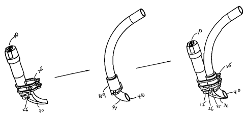
Fig. IA depicts an oblique view of an embodiment of a clip-on access port
according to the present invention.
Fig. 1B depicts a lateral view of the clip-on access port of Fig. 1A.
Fig. IC depicts an embodiment of a cannula adapted for insertion into a vein
or
artery. Fig. 1D depicts a spatial relationship between the access port of Fig.
1B and
cannula of Fig. 1C.
Fig. lE depicts the access port of Fig. 1B attached to the cannula of Fig. 1C.
Fig. IF depicts a blood filter inserted through the access port of Fig. lE.
Fig. 1 G depicts a distal view of the blood filter of Fig. 1 F.
Fig. 2A depicts an oblique view of another embodiment of the clip-on access
port.
Fig. 2B depicts a lateral view of the access port of Fig. 2A.
~ 20 Fig. 2C depicts another embodiment of the cannula having a mounting
mechanism
at its distal region.
Fig. 2D depicts the access port of Fig. 2B attached to the distal region of
the
cannula of Fig. 2C in a predetermined orientation.
Fig. 3A depicts an obturator adapted for insertion into the access port of
Fig. IA.
Fig. 3B depicts a lateral view of the obturator of Fig. 3A.
Fig. 3C depicts the access port of Fig. 3A having the obturator of Fig. 3B
inserted
through its lumen.
Fig. 4 depicts a cannula with a second port adjacent the distal end of the
cannula
and adjacent the first port, wherein the ports and the distal end of the
cannula are arranged
substantially in a line.
&õsEhpED SHEET
= CA 02378577 2002-02-01 = ru 1/UV u U ~ L 1 1 U U
r -,
01 i~--A P. Li;un
6
Fig. 4a depicts a cross-section of the cannula of Fig. 4 through section line
A-A.
Fig. 5 depicts a cannula with a second port adjacent the distal end of the
cannula
and adjacent the first port, wherein the ports are arranged at the vertices of
a triangle.
Fig. 5A depicts a cross-section of the cannula of Fig. 5 through section line
A-A.
Detailed Description
In a first embodiment, a clip-on access port for deployment of medical
devices,
including a blood filter, a balloon occluder, a pressure monitor, an
endoscope, a windsock
~.~
Y=1 filter, a flow director, an atherectomy catheter, an aspiration/suction
catheter, a
cardioplegia catheter, a coronary stent, a graft, and a perfusion catheter, in
a vessel oj
,.;.~
cardiac tissue is provided as depicted in Figs. 1 A and 1 B. The access port
comprises
proximal end 10, distal end 15, and lumen 20. Proximal end 10, which may
include a
hemostatic valve, is adapted to receive a medical device. Attachment mechanism
25,
shown as a plurality of opposed clips, is mounted on distal region 22 of the
access port.
The attachment mechanism is adapted to be removably attached to a distal
region of a
cannula. Flange 30 may be included adjacent the distal end of the access port.
First and
second aligning members 26, which are mounted on distal region 22, can engage
a suture
flange on the cannula. Flange 30 and aligning members 26 fit to ensure proper
circumferential alignment and coupling between the access port and a cannula.
The access port described above can be removably attached to a standard
arterial or
~
venous cannula shown in Fig. 1 C. The cannula has proximal end 35, distal end
40, and
lumen 44. Suture flange 45 may be slideably mounted on distal region 49 of the
cannula
for securing the cannula onto the vascular tissue. Lumen 44 is adapted to
receive
oxygenated or deoxygenated blood. Proximal end 35 is adapted for attachment to
a
bypass-oxygenator machine.
In use for cardiopulmonary bypass, for example, the access port is attached to
distal region 49 of the cannula through attachment mechanism 25 in any
preferred
orientation as depicted in Figs. ID and lE. In certain embodiments, the
alignment will be
fixed by a complementary fit between the clip-on port and the cannula, as by
the
engagement of opposing flat surfaces (e.g., aligning members 26 of the access
port
AMENDED SHEET
CA 02378577 2007-12-04
7
engages suture flange 45 of the cannula, and flange 30 of the access port
engages distal
region 41 of the cannula). After the access port is secured onto the cannula,
distal end 40
of the cannula is inserted through an incision on the aortic wall into the
ascending aorta.
Various medical devices can then be inserted through proximal end 10 and
passed
through distal port 15 of the access port to deploy in the aorta.
In FIGS. 1F and 1G, a blood filter device carrying filter 50 is inserted into
proximal end 10 of the access port. The filter device includes plunger 55,
which upon
activation deploys filter 50 through port 15 of the access port. Filter 50 is
shown in an
expanded state. The reader is referred to Barbut et al., U.S. Pat. No.
5,769,816, Maahs,
U.S. Pat. No. 5,846,260, Tsugita et al., U.S. Pat. No. 5,911,734, and Barbut
et al., U.S.
Pat. No. 5,662,671, for a detailed description of the design and construction
of blood
filter devices. During cardiopulmonary bypass, oxygenated blood will be
delivered to the
aorta from proximal end 35, lumen 44 and distal port 40 of the cannula.
Proximal end 35
is attached to a bypass-oxygenator machine 100 through connector 99. Expanded
filter 50
captures embolic material, such as calcium deposits, atheromatous plaque,
myocardial
tissue debris, and thrombi, generated during cardiac surgery. Alternatively
device 55 can
be any of a balloon occluder, pressure monitor, endoscope, atherectomy device,
aspirator,
drug delivery catheter, blood-sampling device, valvuloplasty catheter,
electrode catheter,
segregating or isolating dams, endoscopic camera, or stent, graft, shunt, and
perfusion
catheters.
In certain embodiments, a second access port can be attached to the first
access
port or the cannula to provide deployment of other medical devices. For
example, a
catheter with a balloon occluder can be inserted into the second access port
to provide
circulatory isolation of the coronary and peripheral arteries. The catheter
can also deliver
carioplegia solution to arrest the heart. Alternatively, multiple ports will
be bonded to
form a single clip-on unit. In this way, the cannula system allows delivery of
multiple
medical therapies to the aorta through one incision, thereby minimizing trauma
to the
aortic wall.
FIGS. 2A and 2B depict another embodiment of the access port, which
comprises proximal end 10, distal end 15, and lumen 20. Proximal end 10, which
includes
= CA 02378577 2002-02-01 = POTNS 0 0/Zj iu u
.?EAIUS41 MAR 2001
8
hemostatic valve 90, is adapted to receive a medical device. Attachment
mechanism 25,
mounted on distal region 22 of the access port, is adapted to engage a distal
region of the
cannula in a specific orientation. Extension member 30 is mounted on distal
end 15 of the
access port to ensure proper attachment to a cannula. In an alternative
embodiment, the
access port may include a second port 80 adjacent the first port, including
proximal
opening 81, lumen 82, and distal port 83.
Another embodiment of the cannula, which is modified to accommodate the
attachment of the access port, is shown in Fig. 2C. The cannula has proximal
end 35,
distal end 40, and lumen 44. Suture flange 45 may be slideably mounted on
distal region
49 of the cannula for securing the cannula onto the vascular tissue. Lumen 44
is adapted
to receive oxygenated or deoxygenated blood. Proximal end 35 is adapted for
attachment
to a bypass-oxygenator machine. Housing 60, which provides a complementary fit
for the
attachment mechanism of the access port, is mounted on distal region 49 of the
cannula.
In use, the access port is attached to distal region 49 of the cannula through
engaging attachment mechanism 25 with housing 60 in a fixed orientation as
depicted in
Figs. 2D. After the access port is secured onto the cannula, distal end 40 of
the cannula is
inserted through the vascular or cardiac tissue of interest. Sutures can be
placed on suture
flange 45 to secure the cannula onto the vascular tissue. Various medical
devices can then
be deploved by inserting through proximal end 10 and passing through distal
port 15 of the
~ 20 access port. Having the access port attached to the cannula in one
orientation may be
preferred in situations where a specific direction of medical device
deployment is required.
In certain embodiments, the access port includes an obturator adapted for
insertion
in proximal end 10 and lumen 20 of the access port as depicted in Figs. 3A,
3B, and 3C.
The obturator has proximal end 61, body 62, and distal end 63. Proximal end 61
includes
releasable engaging mechanism 66 (snap cap), depicted as a latch in Figs. 3A
and 3B.
Gripping members 70 are mounted proximal to the engaging mechanism 66 on
opposite
sides of the obturator. The engaging mechanism is operated by depressing the
gripping
members radially inward for insertion into the access port. Proximal end 61
also includes
porous plug 75, which allows passage of air or gas, but not fluid or blood.
Body 62 of the
obturator has longitudinal grooves 77, which communicate with porous plug 75
and
provide passage for air or gas.
AMENDED SHEET
= CA 02378577 2002-02-01 =eCT/US G 0/ 2110 0
AAIUS01 MAR'n-91
9
In use, the obturator is inserted through proximal end 10 and lumen 20 of the
access port as depicted in Fig. 3C. Distal end 63 of the obturator protrudes
distal to port
15. The access port is then clipped onto a cannula and inserted into a
vascular structure of
interest. When the access port is not in use, the obturator can remain
inserted to prevent
back flow of blood or fluid. Porous plug 75 allows venting of air or gas and
not blood or
fluid. When insertion of a medical device is desired, the obturator is removed
by
depressing gripping members 70 radially inward to release engaging members 66
from
proximal end 10 of the access port, and withdrawing the obturator from the
access port.
The length of the cannula will generally be between 10 and 60 centimeters,
more
preferably approximately 20 to 35 centimeters, more preferably approximately
30
centimeters. The inner diameter of the cannula will generally be between 0.5
and 1.5
centimeters, preferably approximately 1.0 centimeters. The length of the clip-
on access
port will generally be between 2.0 and 10.0 centimeters, preferably
approximately 6.0
centimeters. The inner diameter of the lumen of the access port will generally
be between
0.2 and 1.2 centimeters, preferably approximately 0.6 centimeters. The
foregoing ranges
are set forth solely for the purpose of illustrating typical device
dimensions. The actual
dimensions of a device constructed according to the principles of the present
invention
may obviously vary outFide of the listed ranges without departing from those
basic
principles.
Thus, while the invention has been described in connection with what is
presently
considered to be the most practical embodiment, it is to be understood that
the invention is
not to be limited to the disclosed embodiment, but on the contrary, is
intended to cover
various modifications and equivalent arrangements included within the spirit
and scope of
the appended claims.
AMENDED SHEET