Sélection de la langue

Search

Sommaire du brevet 2384694 

Énoncé de désistement de responsabilité concernant l'information provenant de tiers

Une partie des informations de ce site Web a été fournie par des sources externes. Le gouvernement du Canada n'assume aucune responsabilité concernant la précision, l'actualité ou la fiabilité des informations fournies par les sources externes. Les utilisateurs qui désirent employer cette information devraient consulter directement la source des informations. Le contenu fourni par les sources externes n'est pas assujetti aux exigences sur les langues officielles, la protection des renseignements personnels et l'accessibilité.

Disponibilité de l'Abrégé et des Revendications

L'apparition de différences dans le texte et l'image des Revendications et de l'Abrégé dépend du moment auquel le document est publié. Les textes des Revendications et de l'Abrégé sont affichés :

  • lorsque la demande peut être examinée par le public;
  • lorsque le brevet est émis (délivrance).
(12) Brevet: (11) CA 2384694
(54) Titre français: INSPECTION PAR TRANSDUCTION ELECTROMAGNETO-ACOUSTIQUE DES FISSURES DANS LES TUBES DE CHAUDIERE
(54) Titre anglais: ELECTROMAGNETIC ACOUSTIC TRANSDUCER (EMAT) INSPECTION FOR CRACKS IN BOILER TUBES
Statut: Réputé périmé
Données bibliographiques
(51) Classification internationale des brevets (CIB):
  • G01N 27/82 (2006.01)
  • G01M 3/24 (2006.01)
  • G01N 29/22 (2006.01)
  • G01N 29/24 (2006.01)
(72) Inventeurs :
  • HANCOCK, JIMMY W. (Etats-Unis d'Amérique)
  • MACLAUCHLAN, DANIEL T. (Etats-Unis d'Amérique)
  • MURPHY, RALPH D. (Etats-Unis d'Amérique)
(73) Titulaires :
  • THE BABCOCK & WILCOX COMPANY (Etats-Unis d'Amérique)
  • MCDERMOTT TECHNOLOGY, INC. (Etats-Unis d'Amérique)
(71) Demandeurs :
  • THE BABCOCK & WILCOX COMPANY (Etats-Unis d'Amérique)
  • MCDERMOTT TECHNOLOGY, INC. (Etats-Unis d'Amérique)
(74) Agent: RIDOUT & MAYBEE LLP
(74) Co-agent:
(45) Délivré: 2004-08-24
(86) Date de dépôt PCT: 2000-09-13
(87) Mise à la disponibilité du public: 2001-03-22
Requête d'examen: 2002-03-11
Licence disponible: S.O.
(25) Langue des documents déposés: Anglais

Traité de coopération en matière de brevets (PCT): Oui
(86) Numéro de la demande PCT: PCT/US2000/025087
(87) Numéro de publication internationale PCT: WO2001/020296
(85) Entrée nationale: 2002-03-11

(30) Données de priorité de la demande:
Numéro de la demande Pays / territoire Date
09/398,621 Etats-Unis d'Amérique 1999-09-17

Abrégés

Abrégé français

L'invention concerne un transducteur électromagnéto-acoustique (EMAT) destiné à inspecter, de manière non destructive, la surface d'un tube à la recherche de fissures, et qui, pour ce faire utilise les ondes acoustiques de surface. Ledit transducteur comprend un aimant pulsé dont la surface active fait face à la surface du tube à inspecter. Une bobine EMAT de réception se trouve sur ladite surface active et une bobine EMAT d'émission se trouve sur la surface opposée de la bobine de réception. La bobine EMAT d'émission possède une surface de balayage servant destinée à l'exploration de la surface du tube. Un émetteur servant à générer un signal RF et à le transmettre à la bobine EMAT d'émission permet de générer un signal d'onde acoustique émise le long du tube. L'onde émise créée une onde acoustique réfléchie lorsque l'onde rencontre une fissure dans le tube, et l'onde réfléchie génère un signal de réflexion au niveau de la bobine EMAT de réception. Un récepteur est relié à la bobine EMAT de réception de manière à recevoir ce signal de réflexion. Un calculateur numérique est relié au récepteur de manière à recevoir et à traiter ledit signal de réflexion, et un afficheur affiche les informations relatives à la fissure du tube ayant créé l'onde acoustique réfléchie et le signal de réflexion résultant.


Abrégé anglais


An EMAT device for non-destructive inspection of the surface of a tube for
cracks using acoustic surface waves
includes a pulsed magnet having an active surface for facing the surface of a
tube to be inspected. A receive emat coil is on the active
surface and a transmit emat coil is on the opposite surface of the receive
coil. The transmit emat coil has a scan surface for scanning
over the tube surface. A transmitter for generating and transmitting an RF
signal to the transmit emat coil is provided for generating
a transmitted acoustic wave signal along the tube, the transmitted wave
creating a reflected acoustic wave if a crack in the tube is
encountered, the reflected wave generating a reflection signal in the receive
emat coil. A receiver is connected to the receive emat
coil for receiving the reflection signal. A digital computer is connected to
the receiver for receiving and for processing the reflection
signal and a display displays information about a crack in the tube which
created the reflected acoustic wave and resulting reflection
signal.

Revendications

Note : Les revendications sont présentées dans la langue officielle dans laquelle elles ont été soumises.


We claim:

1. An EMAT device for real-time non-destructive inspection of the surface of a
tube for
cracks using acoustic surface waves, the device comprising:
a pulsed magnet having an active surface for facing the surface of a tube
being inspected;
a receive EMAT coil on the active surface, the receive EMAT coil having a
second
surface opposite the active surface;
a transmit EMAT coil on the second surface of the receive EMAT coil, the
transmit
EMAT coil having a scan surface opposite the second surface, the scan surface
for
scanning over the tube surface;
a transmitter for generating and transmitting an RF signal to the transmit
EMAT coil for
generating a transmitted acoustic wave signal along the tube, the transmitted
wave
creating a reflected acoustic wave if a crack in the tube is encountered, the
reflected wave
generating a reflection signal in the receive EMAT coil;
a receiver connected to the receive EMAT coil for receiving the reflection
signal;
digital computing means connected to the receiver for receiving and for
processing the
reflected signal; and
display means for displaying real-time information about a crack in the tube
which has
created the reflected acoustic wave and resulting reflected wave.

2. An EMAT device according to claim 1, wherein the coils are flexible and
contour to
closely engage the surface of the tube.

3. An EMAT device according to claim 1, wherein the coils and the active
surface are
contoured to closely engage the surface of the tube.

4. An EMAT device according to claim 1, including a wear face over the scan
surface of
the transmit emat coil.

5. An EMAT device according to claim 4, wherein the wear face and the coils
are
flexible.

6. An EMAT device according to claim 4, wherein the wear face is made of UHMW
plastic.

7. An EMAT device according to claim 1, wherein the digital computing means
including
means for displaying, on the display means, information about the presence,
the size and
the position of a crack on the tube.


8. An EMAT device for non-destructive inspection of the surface of a tube for
cracks
using acoustic surface waves, the device comprising:
a pulsed magnet having an active surface for facing the surface of a tube
being inspected;
a receive EMAT coil on the active surface, the receive EMAT coil having a
second
surface opposite the active surface;
a transmit EMAT coil on the second surface of the receive EMAT coil, the
transmit
EMAT coil having a scan surface opposite the second surface, the scan surface
for
scanning over the tube surface, the pulsed magnet and the EMAT coils being
mounted on
a common probe head having a handle connected to the probe head for holding
and
scanning the active surface along the surface of the tube;
a transmitter for generating and transmitting an RF signal to the transmit
EMAT coil for
generating a transmitted acoustic wave signal along the tube, the transmitted
wave
creating a reflected acoustic wave if a crack in the tube is encountered, the
reflected wave
generating a reflection signal in the receive EMAT coil;
a receiver connected to the receive EMAT coil for receiving the reflection
signal;
digital computing means connected to the receiver for receiving and for
processing the
reflected signal; and
display means for displaying real-time information about the presence, size
and position
of a crack in the tube which has created the reflected acoustic wave and
resulting
reflected wave.

9. An EMAT device according to claim 1, wherein the pulsed magnet has a pair
of poles
on opposite sides of the active surface, one pole being narrower than the
other.


Description

Note : Les descriptions sont présentées dans la langue officielle dans laquelle elles ont été soumises.


CA 02384694 2002-03-11
WO 01/20296 - 1 - PCT/US00/25087
ELECTROMAGNETIC ACOUSTIC TRANSDUCER (EMAT)
INSPECTION OF CRACKS IN BOILER TUBES
FIELD AND BACKGROUND OF THE INVENTION
The present invention relates generally to the field of
non-destructive testing of components and in particular to a new
and useful method and apparatus for the non-destructive
inspection of boiler tubes for cracks using electromagnetic
acoustic transducer technology.
Various nondestructive methods such as ultrasonic (UT),
eddy current (ET), magnetic particle (MT), and dye penetrant
(PT), have been used for the detection of cracks in boiler tubes.
All have serious limitations that prevent their use for real
time, high speed inspection of boilers for surface breaking
cracks. UT requires a liquid couplant which can produce
extraneous signals. EC is very susceptible to material
properties/variations inherent within a material which can
produce signals that mask the defect signals or can be mistakenly
interpreted as defects. Both MT and PT require large amounts of


CA 02384694 2002-03-11
WO 01/20296 _ 2 _ PCT/US00/25087
chemicals and are not suited for high speed inspection of boilers
due to the time required for chemical application and signal
interpretation, plus disposal of used chemicals.
Electromagnetic acoustic transducers (here EMATs or emats)
are known for use in testing materials for defects. In known
systems, a signal generator creates an acoustic wave which
propagates through a test material and either the original signal
or a reflection is received by a single sensor having a coil for
converting acoustic wave energy to an electrical current. EMATs
are typically used on planar surfaces of a test material to
detect both surface and sub-surface defects in the test material.
Tubes present a challenge for testing due to their curved
surfaces. Tubes used in industrial boilers present a further
challenge, as the space around and access to the tubes is
typically very limited. These tubes must be as free of defects
as possible, and coated with materials to resist corrosion and
breakdown in the harsh environment of an industrial boiler.
SUNI~iARY OF THE INVENTION
It is an object of the present invention to provide an EMAT
device for non-destructive inspection of the surface of a tube
for cracks using acoustic surface waves which includes a pulsed
magnet having an active surface for facing the surface of a tube
to be inspected. A receive emat coil is on the active surface
and a transmit emat coil is on the opposite surface of the
receive coil. The transmit emat coil has a scan surface for
scanning over the tube surface. A transmitter for generating and
transmitting an RF signal to the transmit emat coil is provided
for generating a transmitted acoustic wave signal around the
tube, the transmitted wave creating a reflected acoustic wave if
a crack in the tube is encountered, the reflected wave generating
a reflection signal in the receive emat coil. A receiver is
connected to the receive emat coil for receiving the reflection
signal. A digital computer is connected to the receiver for
receiving and for processing the reflection signal and a display
displays position information about a crack in the tube which


CA 02384694 2002-03-11
WO 01/20296 _ 3 _ PCT/US00/25087
created the reflected acoustic wave and resulting reflection
signal.
The various features of novelty which characterize the
invention are pointed out with particularity in the claims
annexed to and forming a part of this disclosure. For a better
understanding of the invention, its operating advantages and
specific objects attained by its uses, reference is made to the
accompanying drawings and descriptive matter in which a preferred
embodiment of the invention is illustrated.
BRIEF DESCRIPTION
OF THE DRAWINGS


In the drawings:


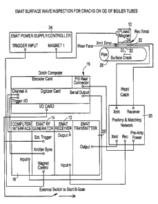
Fig. 1 is a schematic diagram of a testing device


according to the invention;


Fig. 2 is an illustration of a computer output display


of the invention;


Fig. 3 is a schematic perspective view of
a probe of the


invention; and


Fig. 4 is a schematic illustration of a typical emat


coil pattern and dimensions used by the present


invention.


DESCRIPTION OF THE PREFERRED EI~ODIMENTS
Referring now to the drawings, in which like reference
numerals are used to refer to the same or similar elements, Fig.
1 is a schematic diagram showing the components of an
electromagnetic acoustic transducer testing device of the
invention.
The test system shown in Fig. 1 comprises custom EMAT
electronics, including an emat pulser or transmitter 20, receiver
12, RF generator 14, and computer interface 18. RF pulsed magnet
on a probe head 10, transmit and receiver emats 22, 24, preamp
and matching networks 26, and cables are also included. The
unique pulsed magnet and surface wave emat assembly are mounted
in a hand held housing that is rolled down the tubes at
approximately 6-inches/second while acquiring the data in real


CA 02384694 2002-03-11
WO 01/20296 _ 4 _ PCT/US00/25087
time. The magnet is powered by power supply 34. A surface wave
is generated in the tube 28 by the magnetic field from the pulsed
magnet or head 10 and eddy currents produced by the transmit emat
coil 22. This surface wave is bi-directional and follows the
tube surface circumferentially until it is reflected back by a
longitudinal crack 30 originating from the tube OD surface. This
reflected signal returns to the emat receiver coil 24, where it
is detected, amplified, digitized, and displayed on a computer
screen (Fig. 2) in both A-scan and B-scan format for easy
operator evaluation. The data can then be saved to disc if
desired.
In Fig. 1, a digital decoder with encoding card and I/O
card for the computer 18 is shown at 16.
The technique and system of the invention uses a specially
modified pulsed magnet, surface waves, and B-scan display to
allow high rates of scanning and on-line evaluation. The design
of the pulsed magnet and drive pulse have been optimized to make
both as small as possible. In particular, the width of one pole
piece of the magnet was minimized to allow the probe to be
operated as close as possible to the adjacent boiler tube. This
is extremely important in emat operations because of the large
amplitude "main bang" signal produced by the emat pulser/transmit
emat. If the distance from the emats to the area of inspection
is not sufficient, no return signal from the crack will be
detected as it will be lost in the main bang.
In conjunction with the modified pulsed magnet, focused
surface wave emat coil assemblies with conformal backing in the
form of a wear face 32 was used to provide minimum lift-off to
the tube surface. This allowed a small, lightweight probe to be
fabricated that could be easily scanned at high speeds. This
test provides a fast (a complete boiler was inspected at a
Louisiana utility with a two-man crew in 32 hours) and sensitive
(calibrate on a 0.009" deep EDM notch, detection threshold
0.005") real-time inspection of boiler water-wall tubes for
surface breaking cracks.


CA 02384694 2002-03-11
WO 01/20296 _ 5 _ PCT/US00/25087
Utilities have previously used dye penetrant or wet
magnetic particle inspection to test for surface cracks on the
OD's of boiler tubes. These methods are both time consuming and
require large amounts of chemicals when inspecting a complete
boiler. Also the sensitivity of these tests did not meet the
requirements of the utility where we performed the emat surface
wave inspections, as they were still experiencing forced outages
between scheduled shutdowns because of tube failures due to
cracking of the boilers water-wall tubes. This utility has
reported no failures or unscheduled outages due to water-wall
tube failures since their units were inspected with this
technique.
The pulsed magnet may have one or both poles modified in
order to escape the "main bang" signals, the pulsed magnet and
surface wave emats may be modified to detect longitudinal,
circumferential or off-axis cracking, this cracking may be
detected on the "hot" or "cold" (casing) side of the boiler
tubes. Other test frequencies may be employed, and the data can
be displayed in numerous ways, however the B-Scan method with the
signal amplitude displayed in color ranges is an excellent method
of presenting the data to the operator for real-time evaluation.
Wear face or backing 32 is made of ultra high molecular
weight (UHMW) plastic or other wear resistant material which
allows the coil head to slide along the outer surface of the tube
but not interfere with the emat signals from transmit (Xmit) emat
coil 22 or to receive (Rec) emat coil 24. Coils 22 and 24, as
well as face 32 are flexible and contour to the tube diameter,
and the lower active surface or face of pulse magnet 10 can be
curved or contoured to closely engage the tube surface.
Fig. 3 illustrated the probe head 10 which is shown with
the active wear surface of UHMW plastic 32 toward the viewer.
Legs 40 of the emat coil, which is a pitch-catch coil, are
visible beneath the wear surface. Magnetic poles 42 and 44 are
also visible, with pole 44 being narrower than pole 42, for
increased tube surface coverage. A handle 46 is connected to the


CA 02384694 2002-03-11
WO 01/20296 _ 6 _ PCT/US00/25087
frame of probe head 10 so that the probe head can be manually
scanned along the tube surface to be tested.
Fig. 4 illustrates typical dimensions and coil patterns for
the emat coils 22, 24.
While a specific embodiment of the invention has been shown
and described in detail to illustrate the application of the
principles of the invention, it will be understood that the
invention may be embodied otherwise without departing from such
principles.

Dessin représentatif
Une figure unique qui représente un dessin illustrant l'invention.
États administratifs

Pour une meilleure compréhension de l'état de la demande ou brevet qui figure sur cette page, la rubrique Mise en garde , et les descriptions de Brevet , États administratifs , Taxes périodiques et Historique des paiements devraient être consultées.

États administratifs

Titre Date
Date de délivrance prévu 2004-08-24
(86) Date de dépôt PCT 2000-09-13
(87) Date de publication PCT 2001-03-22
(85) Entrée nationale 2002-03-11
Requête d'examen 2002-03-11
(45) Délivré 2004-08-24
Réputé périmé 2010-09-13

Historique d'abandonnement

Date d'abandonnement Raison Reinstatement Date
2004-04-08 Taxe finale impayée 2004-04-27

Historique des paiements

Type de taxes Anniversaire Échéance Montant payé Date payée
Requête d'examen 400,00 $ 2002-03-11
Le dépôt d'une demande de brevet 300,00 $ 2002-03-11
Taxe de maintien en état - Demande - nouvelle loi 2 2002-09-13 100,00 $ 2002-08-19
Enregistrement de documents 100,00 $ 2003-02-19
Taxe de maintien en état - Demande - nouvelle loi 3 2003-09-15 100,00 $ 2003-08-21
Rétablissement - taxe finale non payée 200,00 $ 2004-04-27
Taxe finale 300,00 $ 2004-04-27
Taxe de maintien en état - brevet - nouvelle loi 4 2004-09-13 100,00 $ 2004-08-18
Taxe de maintien en état - brevet - nouvelle loi 5 2005-09-13 200,00 $ 2005-08-19
Taxe de maintien en état - brevet - nouvelle loi 6 2006-09-13 200,00 $ 2006-08-17
Taxe de maintien en état - brevet - nouvelle loi 7 2007-09-13 200,00 $ 2007-08-17
Taxe de maintien en état - brevet - nouvelle loi 8 2008-09-15 200,00 $ 2008-08-18
Titulaires au dossier

Les titulaires actuels et antérieures au dossier sont affichés en ordre alphabétique.

Titulaires actuels au dossier
THE BABCOCK & WILCOX COMPANY
MCDERMOTT TECHNOLOGY, INC.
Titulaires antérieures au dossier
HANCOCK, JIMMY W.
MACLAUCHLAN, DANIEL T.
MURPHY, RALPH D.
Les propriétaires antérieurs qui ne figurent pas dans la liste des « Propriétaires au dossier » apparaîtront dans d'autres documents au dossier.
Documents

Pour visionner les fichiers sélectionnés, entrer le code reCAPTCHA :


Pour visualiser une image, cliquer sur un lien dans la colonne description du document. Pour télécharger l'image (les images), cliquer l'une ou plusieurs cases à cocher dans la première colonne et ensuite cliquer sur le bouton "Télécharger sélection en format PDF (archive Zip)" ou le bouton "Télécharger sélection (en un fichier PDF fusionné)".

Liste des documents de brevet publiés et non publiés sur la BDBC .

Si vous avez des difficultés à accéder au contenu, veuillez communiquer avec le Centre de services à la clientèle au 1-866-997-1936, ou envoyer un courriel au Centre de service à la clientèle de l'OPIC.


Description du
Document 
Date
(yyyy-mm-dd) 
Nombre de pages   Taille de l'image (Ko) 
Dessins représentatifs 2002-07-09 1 11
Page couverture 2002-09-04 2 56
Abrégé 2002-03-11 2 82
Revendications 2002-03-11 2 58
Dessins 2002-03-11 4 87
Description 2002-03-11 6 231
Revendications 2004-04-27 2 80
Page couverture 2004-07-21 2 57
Taxes 2004-08-18 1 35
PCT 2002-03-11 4 190
Cession 2002-03-11 4 134
Correspondance 2002-08-31 1 26
Poursuite-Amendment 2003-01-27 1 42
Cession 2003-02-19 5 293
Taxes 2003-08-21 1 33
Taxes 2002-08-19 1 34
Poursuite-Amendment 2004-04-27 3 130
Correspondance 2004-06-22 1 14
PCT 2002-03-12 3 126