Note : Les descriptions sont présentées dans la langue officielle dans laquelle elles ont été soumises.
CA 02387352 2002-04-08
DESCRIPTION
CORE BODY LOCKING DEVICE OF A CORE DRILL, AND CORE BODY FOR USE
THEREIN
[Technical Field]
The present invention relates to a "core body locking device" of a core drill
having a cylindrical core body and a base body to which the core body is
attached ,
which is capable of attaching the core body to the base body and locking the
core body,
and to a "core body" for use therein.
More specifically, it relates to a core body locking device of a core drill
capable of
detaching a cylindrical core body from a base body, wherein the state of
coupling
between the base body and the core body is fixed so firmly that their coupling
state will
not be impaired due to impact or the like whereby the core drill is suited to
drill an
object to be cut such as concrete or stone, and to a core body for use
therein.
[Background Art]
Conventionally, practical use has been widely made of a core drill which uses
a
cylindrical core body having a drilling blade at a lower end edge thereof to
drill a Iarge-
diameter hole.
A core drill of this type comprises a core body and a base body. The base body
having a shank at an upper part thereof has a attaching portion at a lower
part thereof,
a core body attaching portion with a shoulder portion having a step portion
around the
attaching portion, engagement grooves situated at plural locations on the
outer
periphery of the core body attaching portion, each engagement groove
comprising a
longitudinal groove portion and a transverse groove portion continuous
therewith,
which is concave in section and appears like a hook when viewed from outside,
and a
restraining ball biased to protrude into the transverse groove portion of each
engagement groove by a compression spring thereby holding the engagement
projection
at an engagement terminal point in order to keep the coupling to the core
body. On
the other hand, the core body has the engagement projection corresponding to
each
engagement groove, the engagement projection extending inwardly from an inner
peripheral surface of an upper end portion of the cylindrical core body having
a drilling
blade at a lower end edge thereof.
1
CA 02387352 2002-04-08
The attaching the core body to the base body is achieved by attaching the
upper end
portion of the core body to the core body attaching portion of the base body
to cause the
engagement projections on the core body side to engage the engagement grooves
on the
base body side with the restraining balls being caused to pass through the
engagement
projections against the biasing force of the compression spring.
Such a prior art is described in Japanese Utility Model Examined Gazette No.
HEI 7-
39527 for example.
The core drill of the aforementioned construction allows the core body to be
attached to or detached from the base body easily and hence is excellent in
that, for
example, when it is employed as a cutting tool of a drilling machine such as
an electric
drill, the two are separated from each other to allow masses resulting from
cutting,
which are left within the core body after drilling of concrete, stone or the
like, to be
removed easily.
Though the aforementioned core drill of the construction allowing attaching
and detaching the core body to or from the base body is excellent in that the
state of
coupling between the base body and the core body is stably maintained during a
drilling operation by the arrangement of the hook-shaped engagement grooves
and the
restraining balls if the core drill drills an object at constant revolutions,
the core drill
has the following inconvenience if it is used as a cutting tool of a "rotary
hammer drill",
a sort of drilling machine, to drill concrete, stone or the like. That is,
since the "rotary
hammer drill" imparts periodical axial strikes together with rotation to the
core body
side from the drilling machine side, impactive forces are exerted on the
cutting tool side
during the drilling operation to cause the coupling between the base body and
the core
body to rattle thereby making the coupling state thereof unstable.
Recently, electric drills of the type having a braking mechanism such as to
rapidly stop rotation have been commercially available. When the core drill is
used
with an electric drill of this type, rapid braking during rotation makes the
state of
coupling between the base body and the core body unstable due to rotational
inertia.
The present invention has been made in view of the aforementioned present
circumstances, and it is an object of the present invention to provide a core
body locking
device of a core drill which is free of any one of the aforementioned
inconveniences as
well as a core body for use therein.
[Disclosure of Invention]
2
CA 02387352 2002-04-08
With a view to solving the aforementioned technical problems, a first
invention of the present invention provides a core body locking device of a
core drill
wherein: a base body having a shank at an upper part thereof is provided with
a
attaching portion at a lower part thereof, the attaching portion being
provided with a
core body attaching portion having a shoulder portion formed by a step portion
at an
outer periphery thereof, the core body attaching portion being provided with
an
engagement concave portion; a cylindrical core body having a drilling blade at
a lower
end edge thereof is provided with an engagement projection protruding inwardly
from
an internal surface of the core body at an internal surface of an upper end
portion of the
core body; and the core body is attached to the core body attaching portion of
the base
body by engagement of the engagement projection of the core body with the
engagement concave portion of the base body,
characterized in that:
the core body attaching portion of the base body is provided with a concave
groove portion circumferentially adjacent to and continuous with the
engagement
concave portion and extending therefrom to an lower end of the base body; and
a stopper member which has a lower end portion with an engagement pawl
that is vertically movable within the concave groove portion and which is
downwardly
biased by a spring is disposed on the base body, wherein when the engagement
pawl of
the stopper moves to an unlocking position at an upper location, the concave
groove
portion of the core body attaching portion becomes continuous with the
engagement
concave portion, while when the engagement pawl moves to a locking position at
a
lower location, the engagement concave portion becomes separated from the
concave
groove portion by the engagement pawl.
In the core drill thus constructed according to the first invention, at the
time of
coupling between the base body and the core body the engagement pawl of the
stopper
member on the base body side under the biasing by the compression spring
descends to
a back portion of the engagement projection to press against and lock the
engagement
projection from behind under the condition that the engagement projection of
the core
body engages the engagement concave portion of the core body attaching
portion, so
that the engagement projection is locked from circumferentially opposite sides
by the
engagement concave portion and the engagement pawl, whereby the core body is
locked
so as not to rotate relative to the base body. Accordingly, even if the core
drill is used
with a rotary hammer drill or the like, the coupling between the base body and
the core
3
CA 02387352 2002-04-08
body is not released during the drilling operation and, hence, the
interlocking state of
the two is constantly fixed. That is, the core drill is of an excellent
construction which
is capable of constantly holding the core body as fixed to the base body even
if two
external forces, rotation and periodical strikes, work on the core body at the
same time
to cause an impactive force to be exerted on the core body as in a rotary
hammer drill.
In the coupling operation, the base body and core body of the core drill
according to the first invention act as follows. That is, as the upper end
portion of the
core body is inserted into the concave groove portion of the core body
attaching portion
of the base body from below, the engagement projection of the core body pushes
up the
engagement pawl of the stopper member vertically movably disposed within the
concave groove portion against the force of the spring biasing the stopper
member
downwardly, so that the engagement concave portion, which has been detached
from
the concave groove portion by the engagement pawl, becomes continuous with the
concave groove portion. Under this condition, rotating the core body relative
to the
base body causes the engagement projection of the core body to move to the
engagement
concave portion from the concave groove portion of the base body, so that the
engagement projection engages the engagement concave portion. The move of the
engagement projection to the engagement concave portion causes the lower end
of the
engagement pawl to come off the engagement projection, so that the engagement
pawl
biased downward by the spring descends to the back portion of the engagement
projection. The descent of the engagement pawl causes the back portion of the
engagement projection to be blocked with the engagement pawl thereby locking
the
engagement projection with the engagement concave portion and the engagement
pawl.
In this way, such a coupling operation enables the core body to be attached to
the base body with one touch. Accordingly, this arrangement is also excellent
in
operability in addition to the aforementioned effects provided by the present
invention
and, hence, the operability is improved.
In the construction described above, if an arrangement is provided wherein:
the engagement concave portion is formed such that when the engagement
projection is
in a state engaging the engagement concave portion, the engagement projection
is
locked with its back portion sticking out toward the engagement concave
portion, while
the engagement pawl of the stopper is provided with a concave notch portion
for
receiving the back portion of the engagement projection; and when the
engagement
projection sticking out from the engagement concave portion is caused to enter
the
4
CA 02387352 2002-04-08
concave notch portion of the engagement pawl, the engagement pawl
circumferentially
presses against the back portion of the engagement projection by the biasing
of the
spring to lock the engagement projection of the core body, the back portion of
the
engagement projection is held more stably by the concave notch portion of the
engagement pawl and, hence, the engagement projection is stably locked between
the
engagement concave portion and the engagement pawl. Thus, there is no
possibility
that the core body rattles relative to the base body even if the core body is
subjected to
two actions, i.e., rotation and periodical strikes as in a rotary hammer
drill.
In the construction described above, if concave groove portions of the core
body
attaching portion are formed at three points equally distributed on an outer
periphery
of the core body attaching portion, while, correspondingly thereto, engagement
projections of the core body are provided at three points equally distributed
on an inner
periphery of the core body, such an arrangement allows the stopper member to
move
stably while ensuring firm coupling.
With a view to solving the aforementioned problems, a second invention of the
present invention provides a core body of a core drill which is engageable
with and
lockable to a base body when the core body is in a state attached to the base
body, the
base body being such that: the base body having a shank at an upper part
thereof is
provided with a attaching portion at a lower part thereof, the attaching
portion being
formed at an outer periphery thereof with a core body attaching portion having
a
shoulder portion comprising a step portion; the core body attaching portion is
provided
with an engagement concave portion and a concave groove portion
circumferentially
adjacent to and continuous with the engagement concave portion and extending
therefrom to an lower end of the base body; and a stopper member which has a
lower
end with an engagement pawl that is vertically movable within the concave
groove
portion and which is downwardly biased by a spring is disposed on the base
body,
wherein when the engagement pawl of the stopper moves to an unlocking position
at an
upper location, the concave groove portion of the core body attaching portion
becomes
continuous with the engagement concave portion, while when the engagement pawl
moves to a locking position at a lower location, the engagement concave
portion
becomes separated from the concave groove portion by the engagement pawl,
characterized in that the core body is provided with an inwardly protruding
engagement projection on an internal surface of an upper end portion of the
core body
at a location corresponding to the location of the concave groove portion, the
CA 02387352 2002-04-08
engagement projection being capable of passing through the concave groove
portion and
engaging the engagement concave portion.
The core body thus constructed is suitable as a core body to be used in the
aforementioned core body locking device.
In the core body having the construction described above, if the engagement
projection comprises a hemispherical projection, the core body becomes easy to
manufacture and allows the engagement projection to pass through the concave
groove
portion easily, to move from the concave groove portion to the engagement
concave
portion easily, and to be locked at the engagement concave portion easily.
In the core body having the construction described above, if the engagement
projection is formed at a location that is lower than an upper end of the core
body to
such an extent that at least an upper edge of the engagement projection does
not
contact the upper end of the core body, the core body can be manufactured
easily and
attached to the base body stably and does not lengthen the shaft length of the
core drill
than necessary.
Further, in the core body having the construction described above, if the
diameter of a lower end portion of the core body where the drilling blade is
formed is
different from the diameter of a portion of the core body to be attached to
the base body,
such an arrangement is excellent in that the rigidity of the whole core body
can be
improved by virtue of an improvement in geometric moment of inertia and the
like.
Also, such an arrangement is excellent in that it can be applied to various
core bodies
adapted to drill holes having different diameters for use with a common base
body.
[Brief Description of Drawings]
Fig. 1 is a partially sectional, exploded front view of a core drill showing
an
embodiment of the present invention.
Fig. 2 is a sectional view taken along line A-A and as viewed in the direction
indicated by arrow in Fig. 1.
Fig. 3 is a partially sectional view showing a state immediately after the
beginning of insertion for illustrating the manner of coupling between the
base body
and the core body.
Fig. 4 is a view illustrating the manner of coupling between the base body and
the core body, which shows the same state of insertion as in Fig. 3 as viewed
from a
different angle.
6
CA 02387352 2002-04-08
Fig. 5 is a view illustrating the manner of coupling between the core body and
the base body, which shows a state where the insertion progresses from the
state shown
in Fig. 3 with an engagement pawl in an unlocking position at an upper
location.
Fig. 6 is a view illustrating the manner of coupling between the base body and
the core body, which shows a state where the engagement pawl abuts a back
portion of
an engagement projection of the core body to press against and lock the
engagement
projection.
[Best Mode for Carrying Out the Invention]
Hereinafter, a core body locking device of a core drill and a core body used
in
the device according to an embodiment of the present invention will be
specifically
described with reference to the drawings. However, the present invention is
not
limited to this embodiment. One mode for carrying out the present invention is
described below with reference to the drawings.
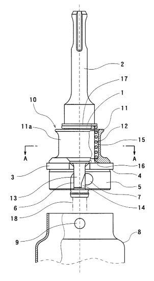
In Figs. 1 and 2, reference numeral 1 denotes a base body having a shank 2
extending upwardly from a central portion of an upper surface of the base body
1. The
shank 2 is chucked to the driving shaft (not shown) of a drilling machine side
by
chucking. The base body 1 has a attaching portion 3 at a lower part thereof.
The
attaching portion 3 has a core body attaching portion 5 on an outer periphery
thereof.
The core body attaching portion 5 has a shoulder portion 4 formed a step
portion at an
upper portion thereof.
Correspondingly to engagement pawls 13 to be described later, concave groove
portions 6 each having an lower end opening to a lower end side of the base
body 1 and
extending from the shoulder portion 4 to a lower end of the core body
attaching portion
are formed at three points equally distributed on the outer periphery of the
attaching
portion 3. An outer peripheral surface of the core body attaching portion 5
situated
below the shoulder portion 4 is provided with engagement concave portions 7
extending
sidewardly (circumferentially) from respective concave groove portions 6.
Engagement concave portion 7 is sized so that when it receives therein an
engagement
projection 9 of a core body 8 to be described later, a back portion (or a
portion of the
back portion) of engagement projection 9 sticks out toward the concave groove
6 side.
On the other hand, the core body 8 to be attached to the base body 1 has a
cylindrical shape as a whole and is provided with a drilling blades (not
shown)
comprising a carbide tip at its lower end edge. Further, the engagement
projections 9,
7
CA 02387352 2002-04-08
which are adapted to pass through the concave groove portions 6 of the core
body
attaching portion 5 and engage the engagement concave portions 7 in the
coupling of
the core body 8 to the base body 1 side, are formed to protrude inwardly at
three points
equally distributed on an inner periphery of an upper end portion of the core
body 8.
In this embodiment, engagement projection 9 comprises a hemispherical
projection.
Engagement projection 9 is formed at a location that is lower than the upper
end of the
core body 8 to such an extent that at least an upper edge of engagement
projection 9
does not contact the upper end of the core body 8. Specifically, in the case
of this
embodiment engagement projection 9 is formed at a location such that the upper
edge
of engagement projection 9 is positioned at a location that is 1.5 to 2 mm
lower than the
upper end of the core body 8. The core body 8 has a different (larger)
diameter at a
portion extending from a location slightly lower than the upper end portion
where
engagement projections 9 are formed and, hence, the core body 8 has an
enhanced
rigidity, particularly against a rotating torque or an axial buckling load.
In the embodiment according to the present invention, a stopper member 11 is
disposed on the base body 1 so that the stopper member 11 and the engagement
concave portion 7, serve as a locking device 10. The stopper member 11 is
vertically
movably disposed relative to the base body 1 and downwardly biased by a
compression
spring (a spring acting to assume its expanded state from its contracted
state) 12. The
stroke of vertical movement of the stopper member 11 is equal to the moving
stroke of
engagement pawl 13 from an unlocking position at an upper location to a
locking
position at a lower location. Even if engagement pawl 13 is movable to an
upper
location than the unlocking position, the basic effect of this embodiment will
result
unless engagement pawl 13 comes off'concave groove portion 6.
The stopper member 11 has a lower portion configured to sliding-contact with
a straight outer periphery having a circular section formed above the
attaching portion
3 of the base body 1 so that the stopper member 11 can vertically move
smoothly
relative to the base body 1. Further, at a portion above the sliding contact
portion is
defined a spring-receiving cylindrical space 15 between an outer peripheral
surface of
the base body 1 and an inner peripheral surface of a cylindrical main body lla
of the
stopper member 11. In the space 15 is accommodated a single compression spring
12
having a winding diameter substantially equal to a central diameter of the
space 15.
The spring 12 has a lower end pressed against a receiving step (receiving
seat) 16
formed at an inner peripheral wall of the cylindrical main body lla of the
stopper
8
CA 02387352 2002-04-08
member 11 and an upper end stopped by a stop ring 1? attached over the base
body 1.
Thus, the spring 12 acts to bias the stopper member 11 downwardly relative to
the base
body 1.
The engagement pawls 13, which protrude downward, are located on the
circumference of the outer peripheral edge of the lower end of the stopper
member 11 at
three points corresponding to the locations of the concave groove portions 6
so as to be
capable of moving vertically within respective concave groove portions 6 and
to
correspond to the concave groove portions 6. When engagement pawl 13 moves to
the
unlocking position at an upper location within concave groove 6, concave
groove portion
6 becomes continuous with engagement concave portion ?, that is, engagement
projection 9 of the core body 8 becomes freely movable between concave groove
portion 6
and engagement concave portion ?. On the other hand, when engagement pawl 13
moves to the locking position at a lower location within concave groove
portion 6,
engagement concave portion ? becomes separated from concave groove portion 6
by
engagement pawl 13, that is, engagement projection 9 protruding into the core
body 8
assumes a locked state where engagement projection 9 is incapable of moving
from
engagement concave portion ? to concave groove portion 6. Stated otherwise,
engagement pawl 13 of the stopper member 11 acts to lock engagement projection
9
relative to engagement concave portion ? from behind engagement projection 9
or to
release this locked state.
In this embodiment, engagement pawl 13 has a concave notch portion 14
shaped like a cutout (a partial bowl shape) at a lower edge portion on the
right-hand
side and adapted to smoothly abut (or conform in shape to) a portion, which
sticks out
toward concave groove portion 6 from engagement concave portion ?, of
engagement
projection 9 at the locking position for receiving that portion (or a part of
that portion).
Thus, the process until engagement pawl 13 locks engagement projection 9
proceeds as
follows. That is, engagement projection 9 pushes up engagement pawl 13, passes
through concave groove portion 6 and engages engagement concave portion ?.
After
this engagement has been made, engagement pawl 13 descends to the back portion
of
engagement projection 13 to cause the back portion of engagement projection 9
sticking
out toward concave groove portion 6 to enter concave notch portion 14 so that
engagement projection 9 is locked as pressed against engagement pawl 13 under
the
biasing by the compression spring 12, thereby holding and fixing engagement
projection 9 within engagement concave portion ?.
9
CA 02387352 2002-04-08
In the case of the core drill according to this embodiment, a center drill 18
is
provided as located in the core body 8 and extending from the center of the
base body 1
through the core body 8 to beyond the front end of the core body 8. Though not
shown,
the center drill 18 has a base portion unrotatably attached into a drill
attaching hole
located centrally of the underside of the base body 1 and is axially secured
by means of
fixing screws screwing from the side direction of the base body. The basic
construction
of the core drill 18 in which the core body 8 and the center drill 18 are
assembled with
the base body 1 is the same as that of a well-known core drill.
Next, description with reference to Figs. 3 to 5 will be made of operations of
each component in the attaching and detaching the core body 8 of the core
drill to or
from the base body 1 having the construction described above.
Referring to Figs. 3 and 4, an operator holds the shank portion 2 with ane
hand and the cylindrical portion of the core body 8 with the other hand to
align
engagement projection 9 of the core body 8 with the lower end of pawl 13 at a
position
lowered within concave groove portion 6 of the core body attaching portion 5
under the
biasing by the spring 12. As the core body attaching portion 5 of the base
body 1 is
inserted into the upper end portion of the core body 8 so that engagement
projection 9
moves upward within concave groove portion 6, engagement pawl 13 is pushed
upward
(toward the shank 2 side) against the compression spring 12.
Then, as shown in Fig. 5, when the upper end edge of the core body 8 becomes
in abutment with the shoulder portion 4 of the base body 1, engagement pawl 13
moves
to the unlocking position at an upper location to make concave groove portion
6 and
engagement concave portion 7 continuous with each other. Subsequently, when
the
core body 8 is rotated relative to the base body 1 (in this embodiment the
core body 8 is
rotated clockwise relative to the base body 1), engagement projection 9 moves
toward
engagement concave portion 7. Under this condition, the back portion of
engagement
projection 9 sticks out into concave groove portion 6 as shown in Fig. 6.
However,
since engagement pawl 13 has a concave notch portion 14 at a lower side end
thereof,
engagement pawl 13 lowers the back portion of engagement projection 9 through
the
biasing force of the spring 12. This descent causes the back portion of
engagement
projection 9 sticking out toward concave groove portion 6 to enter concave
notch portion
14, whereby engagement projection 9 located in engagement concave portion 7 is
pressure-contacted and anchored by engagement pawl 13 and engagement concave
portion 7 under the biasing by the compression spring 12 and, hence, the core
body 8 is
CA 02387352 2002-04-08
made stationary, namely, locked at that position. Of course, the concave
section of
engagement concave portion 7 is configured to fit the sectional shape of
engagement
projection 9 substantially conformably. Though a series of these attaching
operations
includes an axial motion and a rotational motion, these operations are
performed in
series and, hence, the coupling of the core body 8 to the base body 1 can be
achieved on
a so-called "one-touch" basis. In addition, the core body 8 is automatically
locked
relative to the base body 1 by the action of the spring 12 without necessity
of any
operation of the worker.
When the base body 1 and the core body 8 are to be separated from each other,
the worker pulls up the stopper member 11 relative to the base body 1 against
the
compression spring 12 to cause engagement pawl 13 to move upward from the back
portion of engagement projection 9 of the core body 8 thereby unlocking the
core body 8
locked by engagement pawl 13. Thereafter, by reversing the aforementioned
order of
operations, it is possible to detach the core body 8 from the base body 1.
[Industrial Applicability]
The present invention, which is practiced in the aforementioned mode, is
capable of attaching the core body to the base body and automatically locking
their
coupling state and, hence, the coupling relation between the base body and the
core
body is fixed unless the stopper member is pulled up against the compression
spring by
an act of man. Accordingly, even if the core body is used with a rotary hammer
drill, it
is possible to perform a stable and highly reliable drilling operation.
Further, since
the engagement projection of the core body is constantly pressed by the force
of the
spring (resilient force) through the engagement pawl under biasing by the
compression
spring when the base body and the core body are in their attached state, the
core body
does not rattle relative to the base body and, hence, noise can be reduced.
11