Note : Les descriptions sont présentées dans la langue officielle dans laquelle elles ont été soumises.
, ~ I';II I IL i VI 4 I I
CA 02389892 2002-06-07
f"""p-
Device of Wind Electric Power on Transportation Vehicles
Field of Invention
The present invention relates to a device of wind electric power on
transportation vehicles, especially the device that utilizes wind power to
generate electricity as auxiliary power supply of transportation vehicles.
Background.of I,nvention
To reduce the increasingly serious pollution owing to the wide use
of gasoline, experts and scholars all over the world have long dedicated
to the development of electric vehicles as transportation vehicles
considering that they are qualified for environmental protection with high
efficiency in using a variety of energy sources.
Take automobile as an example, there are three types of electric
automobiles. The first one is called Electric Vehicle that stores
electricity of electric utilities in the car borne battery. The second one is
Solar Vehicle that carries multiple solar energy generating units to
generate electricity to be stored in the car borne battery to propel motor.
The third type of electric automobile generates electricity by using fuel
battery. However, it is not widely used because of its huge volume and
high cost. Besides all the three above-mentioned types, there are also
some electric automobiles using all three ways of generating electricity.
However, the criteria by which each country judges the performance
of electric vehicles are based on customers' demand and mainly concern
with top speed, accelerating ability and the distance upon one charging
(so called endurance). Any method that can optimize the performance is
considered as important technical breakthrough in the design of electric
t
CA 02389892 2002-06-07
,/'',
vehicle and will contribute greatly to its popularization.
The traditional electric vehicle, as illustrated in Fig.1, uses electric
supply (10), or solar generator (11) or other electric power such as fuel
battery (12) to store electricity into its car borne battery (13) in advance.
When electric vehicle starts, the battery (13) transmits electricity to
motor (14) to operate (15). Some vehicles are even equipped with a
minor generator (16) that generates electricity through the revolving of
axle to be stored in the battery (13). .lt can be seen from the above facts
that traditional electric vehicle will consume a great amount of electricity
upon start and is hard to recharge to assure its endurance. Therefore,
traditional electric vehicle needs to be improved.
Summary of the Invention
The primary object of the present invention is to provide a device of
wind electric power on transportation vehicles that can be used together
with various traditional electrical installations. The present invention is a
wind electric power-generating unit that unitizes wind power to generate
electricity as auxiliary power supply to enhance the endurance of
electric vehicle and further accelerate its speed.
The further object of the present invention is to provide a device of
wind electric power on transportation vehicles, at its air inlet of the wind
electric power generating unit there is installed a wind-gathering device
that has a pair of air throttles to adjust cross section area of the air
inlet.
Because the present invention can utilizes wind power to generate
electricity when the electric vehicle is running, especially when it
accelerates, to replenish power supply to enhance its endurance, the
2
CA 02389892 2006-03-07
device of the present invention can be used in newly-built electric vehicles
and
even the existing ones as auxiliary power supply to improve its performance.
The device of wind electric power of the present invention can be installed
on one of the transportation vehicles such as electric vehicles or motorcycles
or
bicycles, electric vessels, electric airplanes, etc. This device comprises at
least
one rechargeable secondary battery that can provide electricity to the
electric
transportation vehicle. Moreover, there is fixed a wind electric power-
generating
unit on the empennage and / or the top of the vehicle. The air inlet of the
wind
electric power-generating unit faces the windward side of the vehicle, which
can
help gather airflow when the vehicle is running. The wind electric
power-generating unit is connected to the secondary battery that can store
input
electricity generated by wind power to replenish power supply. A preferred
embodiment of the present invention, at its air inlet of the wind electric
power
generating unit there is also installed a wind-gathering device that has a
pair of air
throttles, preferred that are controlled by motor, to adjust cross section
area of
said air inlet.
Accordingly, in one aspect the present invention resides in a device of wind
electric power on a transportation vehicle comprising at least one wind
electric
power-generating unit fixed on an electric vehicle, and an air inlet of said
wind
electric power generating unit faces a windward side of the transportation
vehicle;
and wherein the air inlet of said wind electric power-generating unit has a
pair of
air throtties that can be pushed outwards to enlarge the cross section area of
said
air inlet.
Brief Description of Drawings
The attached figures illustrate the preferred embodiment of the device of
wind electric power of the present invention.
Fig.1 is schematic of the power supply of traditional electric vehicle.
3
CA 02389892 2006-03-07
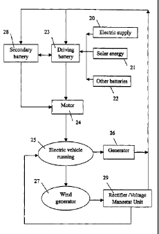
Fig.2 is flow chart of the device of wind electric power on transportation
vehicles and its power utilization.
Fig.3 and Fig.4 are schematics of the embodiments of the present invention
to be applied to general minibus on the top of which is installed the wind
electric
power generating unit; and wherein Fig.3 also
3a
CA 02389892 2002-06-07
illustrates the direction of airflow.
Fig.5 is schematic of the embodiment of the present invention to be
applied to electric jeep.
Fig.6 is schematic of the embodiment of the present invention to be
applied to electric wagon on the front top of which is installed the wind
electric power generating unit.
Fig.7 is schematic of another embodiment of the present invention
to be applied to minibus on the front nose of which is installed the wind
electric power generating unit.
Fig.8 is schematic of the embodiment of the present invention to be
applied to bus on the back top of which is installed the wind electric
power generating unit.
Fig.9 is schematic of the embodiment of the present invention to be
applied to electric motorcycle.
Fig.10 is schematic of the embodiment of the present invention to
be applied to electric bicycle.
Fig.11 and Fig.12 are schematics of the embodiments of the present
invention to be applied to electric vessel.
Fig.13 is top view of the wind electric power-generating unit of the
present invention.
Fig.14 is horizontal view of Fig.13.
Fig.15 is lateral view of Fig.13.
Fig.16 is similar to Fig.13 but illustrates another embodiment.
Fig.17 is horizontal view of Fig.16.
Fig.18 is similar to Fig.4 but illustrates another embodiment.
Fig.19 is top view of the embodiment of the wind electric
power-generating unit in Fig.18.
Fig 20 is lateral view of Fig.19.
Fig.21 is lateral view of the embodiment of the wind electric
power-generating unit in Fig.5.
Fig.22 is upward view of Fig.21.
4
Ih4i Li 91
CA 02389892 2002-06-07
el",
Fig.23 is schematic of the embodiment of the present invention to
be applied to airplane.
Fig.24 is similar to Fig.23 but illustrates another embodiment which
having two row of the wind electric power-generating unit onto each
aerofoil.
Fig.25 is upward view of Fig.24.
Detailed Description of the Preferred Embodiment
As illustrated in Fig.3 and Fig.4 and please refer to Fig.13-23, the
device of wind electric power of the present invention comprises at least
one wind electric power generating unit (30) that is fixed on vehicle (40)
which as shown in Fig.13-23, preferred electric vehicle. The air inlet of
said wind electric power generating unit (30) faces the windward side of
the vehicle (40), which can help gather airflow when the vehicle (40) is
running and promote wind electric power generating unit (30) to
generate electricity to a motor or a battery. Electricity generated by wind
electric power generating unit (30), as shown in Fig.4, can be stored in
a secondary battery (31) (to be connected to main battery 32 via built-in
wire in the vehicle, figure omitted), and can replenish power supply
(please refer to Fig.2) to the motor of the vehicle to propel it to run as
well as enhance the endurance of the vehicle since main battery (32)
can supply more electricity to the motor. In short, a preferred
embodiment of the present invention is as mentioned above to have at
least two connected batteries installed on the electric vehicle (40), the
first of which directly outputs electricity to motor, the second of which
stores input electricity generated bye the wind electric power generating
unit (30).
The electric transportation vehicles to which the present invention
can be applied for minibus (40), preferred electric minibus, shown as
5
~ ~ ~i II d CA 02389892 2002-06-07
A"~_
Fig.4 and Fig.7; jeep (41), preferred electric jeep, of Fig.5; wagon (42),
preferred electric wagon of Fig.6; bus (43), preferred electric bus, of
Fig.8; motorcycle (44), preferred electric motorcycle, of Fig.9; bicycle
(45), preferred electric bicycle, of Fig.10; vessel (46), preferred electric
vessel, of Fig.11 and Fig.12; or other oil tanker that needs wind power
to replenish its power supply, etc. The wind electric power-generating
unit (30) preferred is fixed on the top of the deck, or the stern, or at
least one of the two gunwales of the vessel. When applied to electric
bicycle or motorcycle, said wind ele~ctric power generating unit (30) is
fixed on its front. Fig.23 shown as a preferred embodiment of the
present invention to be applied to airplane (47); and the wind electric
generating unit (30) can be fixed on its wings or other proper place.
When airplane is gliding, it gathers the strong airflow to propel the wind
electric power-generating unit (30) to generate electricity. It is without
doubt that airplane mentioned here is only one of the specific
embodiments of various aircrafts. The present invention can also be
applied to various other aircrafts, such as shown as Fig. 23 or Fig. 24,
for both aero-detecting and recreation, even to glider. It can also be
used together with other generating units such as solar energy
generator as auxiliary power supply to enhance the aircrafts' endurance.
As mentioned above, the air inlet of said wind electric power
generating unit (30) faces the windward side of the electric vehicle.
Take electric vehicle (40) of Fig.3 or electric vessel (46) of Fig.11 and
Fig.12 as example, the wind electric power generating unit is better
installed on the top of the transportation vehicle, which can help gather
airflow and promote wind electric power generating unit (30) to generate
electricity as auxiliary power supply to the motor.
As illustrated in Fig.13 and Fig.15, a preferred embodiment of the
wind electric power generating unit (30) also includes a wind-gathering
6
CA 02389892 2002-06-07
,,='~'+'
device (31) installed at the front of said wind electric power generating
unit (30). Said wind-gathering device (31) comprises a pair of air
throttles (34) that are controlled by a driving unit and can be pushed
outwards to adjust cross section area of said air inlet. Said driving unit
can employ a servomotor (33) to drive a pivot that enables the air
throttles (34) attached to it open and close in a certain angle. When the
electric vehicle remains motionless, the air throttles are closed. Once
the vehicle is running, the air throttles (34) are pushed outwards by the
driving unit to enlarge the cross section-area of the air inlet to gather
airflow.
A preferred embodiment of the wind electric power generating unit
(30) is that it is fixed on the top of the electric vehicle as shown in Fig.9
and Fig.10, on the front top of the vehicle as shown in Fig.7 or on the
back top of the vehicle as shown in Fig.4 and Fig.8. Besides, it can also
be fixed on two different parts at the same time; or as shown in Fig.18,
to be fixed on the top of the vehicle (40) extending from its front to its
back. In this embodiment, the wind electric power-generating unit (30),
as shown in Fig.19 and Fig.20, consists of two or more sets of turbine
generators in series connection. Fig.16 and Fig.17 illustrate an
embodiment in which there are installed multiple wind electric power
generating units (30). Fig.13-15 illustrates a wind electric
power-generating unit (30) consisting of multiple sets of turbine
generators in parallel connection. Moreover, as shown in Fig.21 and
Fig.22, and please refer to Fig.5; different from above-mentioned
horizontal shaft type turbine generator, the present invention can also
be embodied as vertical shaft type turbine generator. When the electric
vehicle is running, as shown in Fig.3, there are fast and strong airflow
above the top of the vehicle. No matter which type of wind power
generator is employed, either the horizontal one of Fig.13-Fig.20 or the
vertical one of Fig.21-Fig.22, it can gather satisfactory airflow upon the
7
CA 02389892 2002-06-07
windward side of the vehicle and generate electricity as auxiliary power
supply. Furthermore, the present invention can also be embodied as
shown in Fig.6, Fig.7 and Fig.8 to have wind electric power generating
unit (30) installed at any of the front top, front or back front of the
vehicle.
The primary obstacle in utilizing wind power to generate electricity
lies in that the airflow is extremely unstable, sometimes strong, and
sometimes weak and sometimes even no airflow at all. Because of this,
traditional windmill-style wind power generator is not supposed to take
place of other means of generating electricity. But what is original in the
present invention is that the wind power generator is installed on a
transportation vehicle and utiiizes the airflow when speeding or even
gliding to generate electricity as auxiliary power supply. In short, the
device of the present invention is actually the best cooperator to other
means of generating electricity on transportation vehicles. It can
generate electricity by utilizing airflow gathered when the vehicle is
running and replenish power supply and further enhance its endurance.
The present invention not only can be applied to newly build electric
vehicles, but also can be equipped to the existing ones as auxiliary
power supply to improve their performance.
As the flow shown in Fig.2, the present invention, like traditional
electric vehicles, can uses electric supply (20), or solar energy
generator (21) or other electric power such as fuel battery (22) to store
electricity into its car borne battery (23) in advance. When electric
vehicle starts, the battery (23) outputs electricity to motor (24) to
operate (25). Some vehicles are even equipped with a minor generator
(26) that generates induced current through the revolving of axle to be
stored in the main battery (23). However, the present invention
specializes in that it utilizes the relative airflow to promote wind power
8
CA 02389892 2002-06-07
a00*'
generator (27) to generate electricity to replenish power supply to
driving motor and the secondary battery stores input electricity
generated by the wind electric power generating unit to drive the vehicle.
Basically, it is possible to employ a rectifier and / or voltage manostat
unit (29) to control electric current. In other hand, as mentioned above,
the present invention can employ a secondary electricity storage device
(28) in parallel connection, i.e., the secondary auxiliary battery (31) as
shown in Fig.4. Thus, the device of the present invention has at least
two connected batteries, the first one of which, i.e., the main battery
(23), directly transmits electricity to the motor, the second of which
stores input electricity generated by the wind electric power generating
unit as auxiliary power supply.
The above-mentioned embodiments give evidence of the operability
of this invention in details. However, if anyone masters this technology
and invents a similar system that has difference either in appearance or
in details, will be held legal responsibility of trespassing the originality
and patent of this invention. Although certain preferred embodiment of
the present invention has been shown and described in detail, it should
be understood that various changes and modification might be made
therein without departing from the scope of the appended claims.
9