Note : Les descriptions sont présentées dans la langue officielle dans laquelle elles ont été soumises.
CA 02390370 2002-07-03
Quick-action coupling of a flat design
The present invention relates to a quick-action
coupling of a flat design.
Quick-action couplings of a flat design substantially
comprise a tube-shaped component to which a cylinder-
shaped, protruding component can be connected.
These quick-action couplings are today usually of a
flat design, i.e. the ends of the coupling parts to be
joined. together are completely closed off when the
coupling parts are not joined together. Quick-action
couplings of a flat design are being used increasingly
in the area of hydraulics, thanks to their most
important property, which is that leakage losses of the
hydraulic oil are avoided when the components of the
coupling are connected or taken apart.
This advantageous property has made it possible for
quick-action couplings also to be used in the area of
agricultural machines or construction machines, since
in fact there are no ascertainable leakage losses of
the hydraulic fluid during the joining together or
taking apart of the coupling parts.
It is to be regarded as one disadvantage of the known
quick-action couplings that the connecting or
disconnecting from each other cannot be carried out if
the individual subassemblies for supplying the
hydraulic fluid and the devices to be driven of the
various items of equipment are under high operating
pressure.
i. I
CA 02390370 2002-07-03
-2-
In the case of the known quick-action couplings of the
first-mentioned type, at the end of the sleeve-shaped
piece of pipe there is usually provided a ring-shaped
component, which surrounds the piece of pipe.
The ring-shaped component can be manually displaced
each time a separation is desired between the
components of the quick-action coupling, by actuating
the ring-shaped component to achieve the effect that
the known arresting balls carry out a radially
outwardly directed movement and enter circumferential
grooves of the displaceable, ring-shaped component and
after that it is possible for the cylinder-shaped
component to be disconnected.
The cited manual actuation of the ring-shaped component
represents an additional working step, which cannot
always be carried out easily and quickly, in particular
whenever the quick-action coupling of a flat design is
used for example in combination with an agricultural
machine or a construction machine.
It can be regarded as a further disadvantage of the
aforementioned quick-action couplings which are already
available on the market that the part of the coupling
of a sleeve-shaped design is connected to the hydraulic
collector of the vehicle with flexible pipelines
interposed, and these pipelines are provided between
the collector and each sleeve-shaped component of the
quick-action coupling.
The connecting between the said components using
flexible pipelines leads to technical difficulties,
however, since these pipelines have proven to be
extremely troublesome and have to be fastened to the
vehicle in a precisely fixed position; furthermore, it
is not possible to rule out the possibility of the
CA 02390370 2002-07-03
-3-
connecting lines being damaged, which leads to an
undesired escape of the hydraulic fluid.
Under direct tensile loading, there is also the risk of
the flexible pipelines tearing or being completely
destroyed, with the consequence that the hydraulic
fluid escapes from the system of lines.
The object of the present invention is to avoid the
disadvantages of the prior art and propose a quick-
action connection which makes it possible to disconnect
the tube-shaped component and the cylinder-shaped
component without entailing the risk of damaging a
connecting line and causing the escape of hydraulic
fluid.
Furthermore, it is intended for the separation of the
components of the quick-action coupling to be possible
without manually acting on a displaceable socket, which
is equipped with a ring of balls for arresting the
joined-together components of the quick-action
coupling, and finally it is intended for dis-
connection of the components of the quick-action
coupling or joining together of these components also
to be possible under high hydraulic pressure in the
pipelines.
The aforementioned objects are achieved by a quick-
action coupling of a flat design which comprises a
sleeve-shaped component and a cylinder-shaped
component, and is characterized in that the radially
outer part of the sleeve-shaped component is connected
to the front side of a tube-shaped part, and the
opposite end of the tube-shaped part is connected to an
end socket, which is connected to a collector or a
valve body for the hydraulic fluid and, in a chamber
bouhded by the tube-shaped component, there is provided
a valve body which is axially displaceable and has an
actuable valve stem, the valve stem being connected to
CA 02390370 2002-07-03
-4-
a tube-shaped component which extends in the
longitudinal direction and ends in a tube-shaped
component which has on its end piece openings which are
arranged in the circumferential direction and receive
arresting balls in a way known per se.
Further advantages and features of the present
invention can be taken from the description which now
follows, the subclaims and the accompanying drawings,
in which:
Figure 1 shows the half of a joined-together quick-
action coupling in section;
Figure 2 shows the half of a quick-action coupling
during a separating operation in section; and
Figure 3 shows the half of a quick-action coupling
after the separating operation has been
carried out.
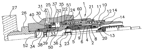
The sleeve-shaped component, which is identified
overall by 1, has in the interior a known, rod-shaped
formation 2, which is mounted on a ring 3, which is
arranged in the channel 33 for the hydraulic fluid to
flow through.
Also arranged in the interior of the sleeve-shaped
component 1 is a tube-shaped displacing piece 4, which
operates with a ring-shaped body 5.
Bearing against the ring-shaped body 5 is a spring 6,
which acts on the displacing piece 4, which is
operatively connected to an outer, known displacing
piece 8, the displacing piece 8 for its part being
loaded by a spring 9.
Arranged on the front side of the sleeve-shaped
component 1 is a socket or displacing piece 10, which
CA 02390370 2002-07-03
-5-
is influenced by a spring 11 and has on the inner side
a ring-shaped projection, which acts on known balls 13,
which in various positions of the displacing piece 10
can be received by a circumferential groove 14 which
has been made in the displacing piece 10.
The cylinder-shaped component has a projection 20 of a
tube-shaped design, which is known from the prior art
and can be introduced into the sleeve-shaped component
4 and also the inner wall of the tube-shaped component.
The components of the quick-action connection described
thus far are known from the prior art.
According to the present invention, the tube-shaped
component 21 is joined together with a tube-shaped
component 22, which on the radially outer side receives
the tube-shaped component 24, which is influenced by a
spring 23 which is blocked between stop means 60
protruding radially from the tube-shaped component 21.
All the components described thus far are accommodated
in a tube-shaped body 24, which is arranged in an
outer, tube-shaped sleeve 25, which serves as a
receptacle.
The tube-shaped sleeve 25 is screwed to an end
connecting piece 26, which for its part is screwed into
a threaded bore which is made in the body 27 of a
collector or a group of valves.
Thanks to the provision of a threaded connecting piece
26, there is the possibility of connecting the body 25,
and consequently the entire sleeve-shaped component,
which is identified overall by 1, directly to the body
of the collector 27, without having to provide
pipelines for this purpose, it being possible in an
advantageous way to dispense with flexible connecting
lines, which are troublesome.
CA 02390370 2002-07-03
-6-
The tube-shaped body 25 has an outlet bore 30, which
allows the hydraulic fluid to be discharged from the
chamber via a small pipe 31.
It is provided that the chamber 32 is in connection
with a longitudinal bore 33 of the connection 1 via a
bore 50.
The chamber 32 receives a valve body 34, which is
connected via a screw connection to the tube-shaped
body 22, which serves as a bearing body, and for its
part is connected to the tube-shaped body 21.
Between the tube-shaped body 22 and the tube-shaped
body 24 there is provided a sealing ring, identified by
35. Between the tube-shaped body 24 and the tube-
shaped body 22 there is also provided a sealing ring
36.
Furthermore, it is envisaged that between the valve
body 34 and the tube-shaped body 24 there is provided a
sealing ring 51 and also between the tube-shaped body
34 and the tube-shaped body 25 there is provided a
sealing ring 52.
Furthermore, between the valve body 24 and the body 25
there is provided a further sealing ring.
Thanks to the provision of the sealing rings 37, 51,
52, which bound compartments in which a hydrostatic
pressure occurs, a situation of equilibrium is
achieved, making it possible for the mechanical
components which are arranged in the interior of the
tube-shaped component 24 to be axially displaced.
It is particularly the case that the sum of the
hydrostatic forces which are fixed by the sealing rings
51 and 52 have the same value as, but are directed in
CA 02390370 2002-07-03
-7-
the opposite direction than, the hydrostatic forces
which are fixed by the sealing ring.37.
The situation of equilibrium allows easy axial
displacement of the entire subassembly, comprising
tube-shaped, inner components, independently of the
pressure prevailing in the hydraulic circuit.
The valve body 34 also has a valve 38, which is
displaced into a blocking position by means of a spring
39.
The valve pin 38 can come to bear against a wall 40,
which serves as a stop.
The way in which the quick-action coupling of a flat
design according to the present invention operates is
as follows:
At the beginning of the joining-together operation,
while the sleeve-shaped component is under pressure,
the cylinder-shaped component is pushed into the
sleeve-shaped component and the thrust of the cylinder-
shaped component occurring in the axial direction
brings about a return of the displaceable socket 8
until it comes to bear against the tube-shaped socket
4, which is arrested by the internal pressure
prevailing in the interior of the sleeve-shaped
component.
If the connecting operation is continued, the entire
inner component moves further back and stresses the
spring 23.
At the same time, the valve 38 comes into contact with
the wall 40 of the sleeve 25 and consequently opens the
valve 38 against the action of the spring 39. Opening
of the valve consequently makes it possible for part of
the hydraulic fluid of the circuit to escape via the
CA 02390370 2002-07-03
-8-
bore 30 and flow away via the small pipe 31, which
leads to a reduction in the internal pressure.
The escaping hydraulic fluid is returned to the main
tank of the hydraulic system of the machine via the
small pipe 31.
The reduction in the pressure inside the sleeve-shaped
component of the quick-action coupling leads to an
unlocking of the socket 4 of a tube-shaped design and
consequently makes it possible for the cylinder-shaped
component to be introduced into the interior of the
sleeve-shaped component until the groove which is
provided at the front end of the protruding part of the
cylinder-shaped component allows the balls 13 to run
into the groove 12, thereby making it possible for the
cylinder-shaped component to be completely inserted.