Note : Les descriptions sont présentées dans la langue officielle dans laquelle elles ont été soumises.
CA 02393103 2005-05-05
1505
CONTROL VALVE WITH INTEGRAL SOLENOID
AND REGULATOR FOR GAS APPLIANCES
FIELD OF THE INVENTION
[02] The present invention relates to a control for gas appliances, such as
gas ranges, and
more particularly relates to an integrated control valve that integrates the
function of a gas
pressure regulator, a manual shutoff valve and a solenoid operated gas valve.
BACKGROUND OF THE INVENTION
[03] Conventional controls for gas appliances, such as gas ranges, gas clothes
dryers or
gas water heaters, provide a regulated control of an unregulated gas supply.
For example,
with respect to a control used for gas ranges, an arrangement may have a
single gas inlet
from which an unregulated gas supply is connected and two outlets, which
provide a pressure
regulated gas supply. One of these outlets provides a direct connection from
the output of
the pressure regulator and is commonly used to provide a constant supply of
gas, such as to
the top burners of a gas range. the outlet is typically configured for some
sort of pipe fitting
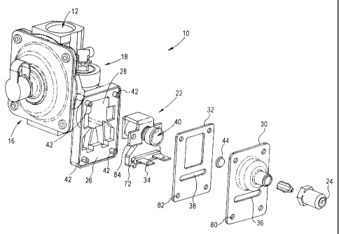
to carry the gas to the top burners. The other gas outlet, when employed with
a gas range,
typically supplies the oven burner with gas. The gas from this outlet passes
througih the
manual shutoff valve and then a solenoid operated gas valve. The manual
shutoff valve is
required to allow the user to manually shut off gas supplied to the solenoid
valve in case of a
malfunction.
WDC99 621223-1.054265.0504
CA 02393103 2002-07-11
2
[04] In conventional arrangements, the solenoid valve is a separate component
from the
gas pressure regulator and manual shutoff valve. Hence, the solenoid assembly
is external to
the gas chamber and is exposed to the external environment and high operating
temperatures.
A high operating temperature of the solenoid assembly will cause degradation
in the holding
force performance of the solenoid assembly. Furthermore, an external solenoid
assembly
requires an intermediate substrate between the armature and the coil to seal
the gas. This
increases the distance between the coil and the armature of the solenoid,
thereby reducing the
magnetic coupling.
[OS] Another disadvantage of conventional construcrions is that the coil is
exposed to
potential mechanical damage during shipping and handling. In order to avoid
such
mechanical damage, externally mounted coils are protected or encapsulated by a
tape, adding
to the cost of the control valve.
SITNEVIARY OF THE INVENTION
[06] There is a need for a gas control valve that integrates the functions of
a gas pressure
regulator, manual shutoff valve and solenoid operating gas valve, but in a
manner that
reduces the degradation in the holding force performance of the solenoid
valve, provides a
superior magnetic coupling to the armature, and reduces the potential for
mechanical damage
during shipping and handling.
[07] These and other needs are met by embodiments of the present invention
which
provide a control valve with integrated solenoid valve and regulator for gas
appliances,
comprising a cast body having a casting configured to receive a solenoid
valve. The control
valve includes a gas pressure regulator and a shutoff valve mechanism on the
cast body. A
solenoid valve is received in the casting so as to be internally mounted in
the control valve.
[08] The internal mounting of the solenoid valve within the casting allows a
solenoid to be
inside of the gas chamber rather than external to the chamber. This keeps the
coil from being
exposed to the external environment. As a result, the coil can stay cooler
than those coils
mounted externally because the gas flows around the assembly and cools it. The
lower
WDC99 621223-1.054265.0504
CA 02393103 2005-05-05
3
operating temperature reduces degradation in the holding force performance
that can be caused
by high temperatures.
[09] The arrangement of the invention also allows for a superior magnetic
coupling to the
armature. The present invention does not require an intermediate substrate
between the
armature and the coil to seal the gas, which would increase the distance
between the coil and
the armature and reduce the magnetic coupling. Instead, a small solenoid can
be used to attain
the desired amount of force.
[ 10] Furthermore, the arrangement of the solenoid valve received in the
casting so as to be
internally mounted within the control valve prevents the coil from being
exposed to the
potential for mechanical damage during shipping and handling. This avoids the
need for
protecting the coil with a tape, which would lead to additional costs.
[ 11 ] The earlier stated needs are also met by other embodiments of the
present rove ration
which provide a gas control valve having a single cast body with a gas
pressure regulator and
manual shutoff valve mechanism. The gas control valve includes a gas chamber
formed by
the cast body, and a solenoid valve assembly with a coil and armature enclosed
within the gas
chamber. A cover seals the solenoid valve assembly within the gas chamber. The
gas control
valve has a gas inlet and a first gas outlet formed by an outlet of the gas
pressure regulator.
A second gas outlet of the gas control valve is formed on an outlet of the
cover. There is a gas
flow path from the gas inlet through the manual shutoff valve, the solenoid
valve assembly and
the second gas outlet. The solenoid valve assembly controls the flow of gas
through the
second gas outlet.
[ 12a] According to the present invention then, there is provided a control
valve with
integrated solenoid valve and regulator for gas appliances, comprising a cast
body having a
casting configured to receive a solenoid valve; a gas pressure regulator and a
shutoff valve
mechanism on the cast body; and a solenoid valve received in the casting so as
to be internally
mounted within the control valve.
[ 12b] According to another aspect of the present invention, there is also
provided a gas
control valve having a single cast body with a gas pressure regulator and a
manual shutoff
valve mechanism, comprising a gas chamber formed by the cast body; a solenoid
valve
assembly with a coil and armature enclosed within the gas chamber; a cover
sealing the
solenoid valve assembly within the gas chamber; a gas inlet to the gas control
valve; a first gas
outlet of the gas control valve formed by an outlet of the gas pressure
regulator; a second gas
CA 02393103 2005-05-05
3a
outlet of the gas control valve formed at an outlet of the cover; and a gas
flow path from the
gas inlet through the manual shutoff valve, the solenoid valve assembly and
the second gas
outlet, the solenoid valve assembly controlling flow of gas through the second
gas outlet.
[ 12c] The foregoing and other features, aspects and advantages of the present
invention will
become more apparent from the following detailed description of the present
invention when
taken in conjunction with the accompanying drawings.
BRIEF DESCRIPTION OF THE DRAWINGS
[ 13] Figure 1 is an exploded view of an integrated control valve constructed
in accordance
with embodiments of the present invention.
[14] Figure 2 shows the valve of Figure 1 from a different angle.
CA 02393103 2002-07-11
4
[15] Figure 3 depicts the gas control valve of the present invention in an
assembled state,
from a first perspective.
[ 1 b] Figure 4 shows the gas control valve of Figure 3 from a different
perspective.
[ 17] Figure 5 shows the gas control valve of Figures 3 and 4 coupled to a
venturi of an
oven burner.
[18] Figures 6 and 7 show exploded views of a solenoid assembly constructed in
accordance with the present invention from different perspectives.
j19] Figure 8A and 8B depict a cross-section of the solenoid valve inserted
within the gas
chamber of a cast body of the gas control valve according to embodiment of the
present
invention.
[20J Figure 9 shows an exploded view of the gas'control valve of the present
invention,
but with a diffenmt gas outlet configuration on the cover of the solenoid
valve assembly.
[21] Figure 10 depicts a gas control valve constructed in accordance with
alternative
embodiments of the present invention. -
[22] Figures 11 and 12 show exploded views of the solenoid valve assembly
employed
with the alternative embodiment of Figure 10.
[23] Figures 13A and 13B show the enclosure into which a solenoid assembly
valve of
Figures 11 and 12 is inserted. Figure 13A is a slightly perspective view,
while Figure 13B is
a top-down view.
[24] Figures 14 and 15 respectively illustrate the solenoid assembly of the
present
invention arranged in a gas supplying application, as viewed from different
perspectives.
DETAILED DESCRIPTION OF THE I1WENTION
[25] The present invention addresses and solves problems related to the
integration of
fixnctionality in a gas control valve of the gas pressure regulation, manual
shutoff and a
solenoid operated gas valve. In particular, the present invention overcomes
some of the
problems associated with a separate solenoid gas valve externally mounted to a
gas pressure
regulator and a manual shutoff valve.- This is achieved, in part, by the
provision of a solenoid
gas valve assembly within a gas chamber of a cast body that is integral with
the gas pressure
WDC99 621223-1.054265.0504
CA 02393103 2002-07-11
S
regulator and a manual shutoff valve. The integration of the valve into the
regulator reduces
the number of parts and the labor required for assembly. The location of the
solenoid
assembly inside of the gas chamber keeps the coil firm being exposed to the
external
environment. As a result, the coil can stay cooler than those mounted
externally because the
gas is flowing around the assembly and cools it. This lower operating
temperature reduces
degradation in the holding force performance caused by high temperatures. The
configuration also allows for a superior magnetic coupling to the armature. An
external
solenoid, such as in the prior art, requires an intermediate substrate between
the armature and
the coil to seal off the gas. This increases the distance between the coil and
the armature,
thereby reducing the magnetic coupling. However, with the present invention, a
smaller
solenoid can be used to attain the desired amount of force. Because the
solenoid valve is
inserted within the gas chamber, the coil is not exposed to the potential for
mechanical
damage during shipping and handling, and reduces manufacturing costs since the
coil does
not have to be encapsulated or protected by tape.
[26] Figures 1 and 2 depict exploded views of the gas control valve 10 of the
present
invention, taken from different perspectives. Figures 3 and 4 show the same
valves, but in an
assembled state, again taken from different perspectives. Referring now to
Figures 1-4, the
gas control valve 10 has a gas inlet 14 wherein an unregulated gas supply is
connected. A
first gas outlet 12, also referred to as the range gas outlet, provides a
direct connection to the
output of the regulator and may be used to provide a constant pressure supply
of gas to the
top burners of a gas range, for example. The first gas outlet 12 is typically
configured for
some sort of pipefitting to carry the gas to the top burners.
[27) A second gas outlet 20, forming the oven gas outlet, for example, may be
connected
to supply an oven burner in a gas range that has one oven burner. The gas from
the second
gas outlet 20 passes through a manual shutoff valve 18 and then a solenoid
valve assembly
22 (also referred to as a "solenoid valve"). The gas regulator 16 is also
integrated into the
control valve 10 and provides the pressure regulation of the gas.
[28] The manual shutoff valve 18 is required to allow a user to manually shut
off the gas
supply to the solenoid valve assembly 22 in case of malfunction.
WDC99 621223-1.054265.0504
CA 02393103 2002-07-11
6
[29] Figures 1-4 depict a gas orifice 24 of a certain configuration. As seen
in Figure 5, the
gas orifice 24 at the second gas outlet 20 provides gas to a venturi 46 of the
oven burner.
The orifice assembly 24 may be connects to a male thread at the gas outlet 20
to control the
flow of the gas from the second gas outlet 20. Referring briefly to Figure 9,
another
embodiment of the gas control valve 10 employs a threaded fitting 78 to
provide a
connection to a remotely mounted orifice. Other outlet configurations can be
employed by
changing the cover of a solenoid valve assembly 22, as will become more
apparent from the
following descriptions.
[30] Referring back to Figures 1-4, the gas control valve 10 has a cast body
26 with a gas
chamber 28. As can be appreciated from the figures, the cast body 26 is
directly formed with
the gas control valve 10. The solenoid valve assembly 22 is inserted into the
gas chamber 28
of the cast body 26, and thus integrates the fimcdon of a solenoid gas valve
with that of a gas
pressure regulator and a manual shutoff valve.
[31] The solenoid valve assembly 22 includes electrical terminals 34 that
carry electrical
power to the solenoid valve assembly 22. A cover 30 seals the solenoid valve
assembly 22
within the cast body 26. The cover 30 includes an opening 36 through which the
terminals
34 extend. A first boss 72 on the solenoid valve assembly 22 closely mates
with the opening
36.
[32] A gas-tight seal is provided by a gasket 32 that has a corresponding
opening 38 that
also closely matches with the first boss 72. The gasket 32 is compressed by
the cover 30
against the surfaces of the cast body 26. The cover 30 has holes 80 and the
gasket 32 has
holes 82 thmugh which bosses on the cast body 42 extend when the gasket 32 and
the cover
30 are assembled onto the cast body 26. These bosses 42 are rolled over to
stake the cover
30 onto the cast body 26 during assembly. A screen 44 is inserted into the
cover 30 prior to
assembly.
[33] Tabs 84 of the solenoid valve assembly 22 are trapped between the gasket
32 and the
cast body 26 during assembly. When the cover 30 is staked, the gasket 32
compresses and
firmly retains the solenoid valve assembly 22 without the use of fasteners.
The raised first
boss 72 on the solenoid valve assembly 22 registers directly to the opening 36
and the cover
WDC99 621223-1.054265.0504
CA 02393103 2002-07-11
7
30. This construction significantly reduces tolerances involved in centering
the valve seal 40
on the sealing surface (not shown). By contrast, typical solenoid mounting
schemes involve
attaching the solenoid frame to a mounting surface, which then positions it at
the point of
interest.
[34] Referring now to Figures 6 and 7, exploded views of a solenoid valve
assembly 22
constructed in accordance with certain embodiments of the present invention
are depicted
from different perspectives. The solenoid valve assembly 22 is held by a frame
48 having a
first recess S2 and a second recess S4. The solenoid valve assembly 22
includes a bobbin SO
on which a coil 60 and an armature 62 are carried.
[3S] The bobbin SO has a second boss S6 and a third boss S8 that provide snap-
in
connections to the first and second recesses S2, S4. The snap-in connections
connect the
bobbin SO to the frame 48.
[36] A spring 64 returns the armature 62 from its energized position to its
unenergized
position. A spring retaining washer 66 retains the return spring 64 in
position, and also holds
the valve seal 40.
[37] A sound absorbing pad 70, made of Teflon, for example, prevents metal to
metal
contact. The sound absorbing pad 24 is registered to the bobbin SO by the
third boss S8 and a
hole 68 in the sound absorbing pad 70.
[38] Figure 8A shows the solenoid valve assembly 22 in cross-section with the
valve open
and the armature 62 pulled in with the coil 60 energized. The valve seal 40 is
lifted off the
valve opening 74 on the cover 30.
[39] In Figure 8B, the valve opening 74 is closed when the solenoid valve
assembly 22 is
de-energized (the coil 60 de-energized) and the armature 62 is extended. As
can be
appreciat~l from Figures 8A, 8B, the coil 60 is located within the gas chamber
28 so that gas
may flow around the coil 60 and thereby cool the coil 60. This lower operating
temperature
reduces degradation in the holding force performance due to high temperatures.
The
configuration also allows for a superior magnetic coupling to the armature,
since it does not
require an intermediate substrate between the armature and the coil to seal
the gas. Because
of this, a smaller solenoid can be used to attain the desired amount of force.
Also, by
WDC99 621223-1.054265.0504
CA 02393103 2002-07-11
8
locating the solenoid valve assembly 22 within the gas chamber 28, the coil 60
is not exposed
to potential mechanical damage during shipping and handling. ,
[40] The assembly of the gas control valve 10 is an elegant process that lends
itself to
automated assembly. As can be appreciated from Figures 1 and 2, the parts can
be assembled
in one direction into the gas chamber 28 (a cavity) in the cast body 26. The
solenoid
assembly 22, after being fitted together by the snap connections formed by the
second and
third bosses 56, 58 and the first and second recesses 52, 54 of the frame 48,
is inserted first.
The gasket 32 is fitted over the bobbin 50 of the solenoid valve assembly. The
first boss 72
extends thmugh the opening 38 and the gasket 32. Similarly, the bosses in the
cast body 26
extend through the openings 82 and the gasket 32. The tabs 84 fit within the
recesses in the
cast body 26. The cover 30 is then placed over the gasket 32, with the first
boss 72 and
terminals 34 extending through the opening 36 in the cover 30. The cover 30 is
staked onto
the cast body 26 by rolling over the four bosses 42 on the cast body 26 that
protrude through
the openings 80 in the cover 30. The screen 44 is inserted into the cover 30
prior to the
completion of the assembly. The adjustable orifice 24 is assembled to the
cover at any time
during the assembly process.
[41 ] Alternative embodiments of the present inventions are depicted in Figure
10-15. The
solenoid action is inverted, in comparison to that the embodiments of Figures
1-9, to provide
the actuation finm the end opposite the electrical terminals 88, in comparison
to the
embodiments of Figures 1-9 in which the actuation originates from the same end
as the
terminals 34. This allows the main enclosure 92, typically a casting, to have
a bottom 96 that
is machined to provide a sealing area for the valve 98. This simplifies the
stamped metal
cover 94 that is placed over the solenoid by eliminating the drawn portion, as
depicted in the
cover 30 of the embodiments of Figures 1-9. The embodiment of Figures 10-15
also
eliminates a need for a cover 30 made of a casting for applications that
require the outlet to
be at a 90° angle from the solenoid actuation. In both cases, this
simplifies the tooling and
significantly lowers the cost. Another advantage of this construction is that
the rubber gasket
90 is now against the portion of the solenoid frame 87 that the armature 89
strikes when the
armature pulls in. This significantly lowers the noise level when the armature
89 pulls in.
WDC99 621223-1.054265.0504
CA 02393103 2002-07-11
9
[42] The construction and assembly of the solenoid are shown in Figures 11-12.
The
solenoid assembly 86 has inserted molded terminals 88 with a sealing face 91
that is formed
around the terminals 88. The armature 89 is inserted into the bore of the coil
93 and a
magnetic shading pad 95 is placed over the top. The coil 93, the armature 89
and the
magnetic shading pad 95 are then snapped into the frame 87 to create the
assembly 86
depicted in Figure 12. A return spring 97, spring washer 99 and valve seal 98
are assembled
to the end of the armature 89, thereby completing the solenoid assembly. The
solenoid
assembly 86 is inserted into the enclosure shown in Figures 13A and 13B. At
the bottom of
the enclosure are pockets 100 that receives the two tabs 102 on the solenoid
frame 87 to
register the solenoid assembly 86 to the sealing surface 96. The tabs 104 on
the solenoid
frame at the terminal end rest on a pad 106 of the enclosure to set the height
of the solenoid
assembly 86. The rubber gasket 90 is then placed over the solenoid assembly 86
with the
terminals 88 protruding therethrough. The stamped cover 94 is then placed over
the gasket
90 and fastened in place. Although Figure I0 depicts screw fasteners, other
fastening
methods can be used. When the rubber gasket 90 is compressed, it sandwiches
the tabs 104
on the solenoid frame 87 between the enclosures and the gasket 90 and fastens
the solenoid
assembly 86 in place.
[43] Figures 14 and 15 show embodiments in which two solenoid assemblies, such
as
solenoid assembly 22, may be employed in an exemplary application. A plurality
of these
solenoid valve assemblies 22 may be used in a control with a regulator or the
valve or may
stand alone.
[44] Although the present invention has been described and illustrated in
detail, it is to be
clearly understood that the same is by way of illustration and example only
and is not to be
taken by way of limitation, the scope of the present invention being limited
only by the terms
of the appended claims.
WDC99 621223-!.054265.0504