Note : Les descriptions sont présentées dans la langue officielle dans laquelle elles ont été soumises.
CA 02396970 2002-04-16
WO 02/21116 PCT/US01/27572
ELECTROPHORESIS CELL
FOR MULTIPLE SLAB GELS
BACKGROUND OF THE INVENTION
1. Field of the Invention
This invention arises in the field of electrophoresis apparatus, and relates
in particular to cell designs for electrophoresis in slab gels.
2. Description of the Prior Art
Electrophoresis in slab gels offers versatility and speed to the laboratory
technician performing analyses of biological samples. A single slab gel can
serve as the
separation medium in which a large number of individual samples can be
analyzed
siinultaneously by dividing the slab into parallel lanes and using one lane
for each
sample. This affords not only speed and an efficient use of labor, energy,
materials,
equipment, and time, but also eliminates many of the problems that commonly
arise when
separate procedures are performed on each of a series of samples, the problems
including
for example nonuniforinity that arises from variations in gel quality and
operating
conditions and the risk of operator error. One of the most important uses of
slab gels
however is in the performance of two-dimensional electrophoresis, in which a
first
dimension separation is performed in a linear medium such as a gel tube or
strip, wllich is
then placed along one edge of the slab for a second dimension separation in a
direction
transverse to the axis of the linear medium. In two-dimensional
electrophoresis, one of
the most common separation techniques for the first dimension separation is
isoelectric
focusing. The second dimension separation is then performed by any of the
various
forms of traditional electrophoresis, with the result that each of the zones
formed in the
first dimension is separated into its components. Thus, in addition to the
efficiency that
slab gels provide in the performance of multiple separations, slab gels permit
the
1
CA 02396970 2002-04-16
WO 02/21116 PCT/US01/27572
separation of highly complex protein mixtures that could not be separated in a
single
dimension separation.
Efficiency and uniformity in slab gel electrophoresis are improved even
more when a series of slab gels are run simultaneously in a cominon
electrophoresis cell
with a cominon buffer solution and a common temperature and electrical
potential.
Various=cell designs have been proposed, and a representative example is that
disclosed in
United States patent no. 4,088,561, to Norman L. Anderson, issued May 9, 1978.
The
Anderson patent shows a cell that accommodates ten slab gels in an elongated
rectangular
chamber with wire grids on each side of the gel slab array to serve as
electrodes. Typical
problems encountered in the use of these cells include the difficulty of
achieving a
uniform electrical field extending over all of the gels, and the difficulty of
controlling the
temperature of the gels since the heat generated by current running through
each gel is
compounded when a multitude of gels is present.
SUMMARY OF THE INVENTION
The difficulties enumerated above and others associated with
electrophoresis cells designed to accommodate se-ieral slab gels are addressed
by the
present invention, which resides in a multi-slab gel electrophoresis cell in
which plate
electrodes are used to establish the electric potential, and in which buffer
solution is
circulated through the cell interior in a circulation path that causes buffer
to flow
continuously through the cell in an upward direction while contacting each gel
slab
cassette in the cell. In preferred embodiments of the invention, internal
cooling of the cell
is also provided, most preferably by a loop of circulating coolant positioned
near the floor
of the cell so that the circulating buffer solution is cooled near the bottom
of the cell
before flowing upward past the slab gels. In still further preferred
einbodiments of the
invention, specially designed retaining members are included in the cell
design both to
hold the gel cassettes in place and to minimize or prevent the bypass of
current flow
around the gels and between the different compartments of the cell that serve
as the anode
compartment and the cathode compartment. The retaining members are also
designed to
minimize or prevent fluid and current leakage when the number of gel cassettes
installed
in the cell is less than the maximum number that the cell accommodates.
These and other objects, advantages, features and embodiments of the
invention will be apparent from the description that follows.
2
CA 02396970 2002-04-16
WO 02/21116 PCT/US01/27572
BRIEF DESCRIPTION OF THE DRAWINGS
FIG. 1 is a perspective view in partial cutaway of an electrophoresis cell in
accordance with this invention, showing a tank and lid and some of the
internal parts.
FIGS. 2a and 2b are views of one of the two gel cassette supports that are
included in the cell of FIG. 1. FIG. 2a is a top view and FIG. 2b is a front
elevation.
FIGS. 3a and 3b are cross section views of a portion of the gel cassette
support of FIGS. 2a and 2b, the portion being that in which the gel cassette
is inserted.
FIG. 3a shows the configuration of the portion with no gel cassette installed,
while FIG.
3b shows the configuration of the portion with a gel cassette installed.
FIG. 4 is a front elevation of one of the electrode plates that are included
in
the cell of FIG. 1.
FIG. 5 is a perspective view of the exterior of the cell of FIG. 1 showing
the components of the buffer circulation system and the cooling system.
FIG. 6 is a view from above of the tubing along the floor of the tank
portion of the cell of FIG. 1, showing portions of the buffer circulation
system and the
cooling system.
FIG. 7 is a longitudinal cross section view of the cell of FIG. 1.
DETAILED DESCRIPTION OF THE INVENTION
AND SPECIFIC EMBODIMENTS
While this invention is susceptible to a wide range of configurations,
arrangements and embodiments, the following discussion will focus on a
specific
example, the structural and functional aspects of which will serve to provide
an
understanding of the invention as a whole.
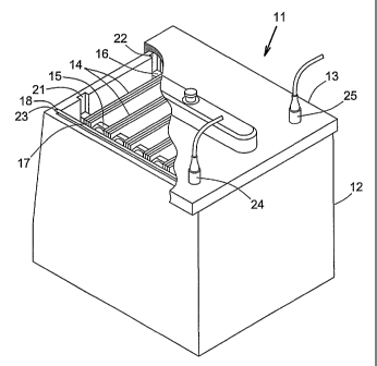
FIG. 1 depicts an electrophoresis cell 11 in accordance with this invention,
the cell including a tanlc 12 and a removable lid 13 that fits over the open
top of the tank
to protect the tank contents from external objects and the environment and to
reduce
evaporation losses from the tank, and whose removal permits easy access to the
tank
interior. The tank 12 accommodates several gel cassettes, some of which 14 are
visible in
the drawing. The gel cassettes are held in vertical orientation and parallel
to each other
by cassette supports 15, 16.
The gel cassettes with which this invention can be used are conyentional in
construction, and many designs and constructions are known in the art and
widely used.
3
CA 02396970 2002-04-16
WO 02/21116 PCT/US01/27572
Slab gel cassettes generally consist of a pair of rectangular flat plates,
preferably of
transparent material such as glass or plastic, joined to each other with
appropriate spacers
to establish a gap of controlled and precisely known width which serves as the
gel space.
The slab gel is cast in the space in such a manner that two opposing edges of
the slab are
left exposed for electrical contact, either with electrodes or with buffer
solutions in which
electrodes are immersed, and electrophoretic migration proceeds in the
direction from one
exposed edge to the other.
Accordingly, each cassette 14 shown in FIG. 1 appears as a three-layer
structure of which the outer two layers are the inert support plates and the
inner layer is
the gel. The exposed edges of the gels are the vertical edges, with only one
vertical edge
17 of each gel being visible in the view presented. Facing the exposed edges
on each side
are plate electrodes, of which only one 18 is visible. The vertical edges of
the cassette
supports 15, 16 mate with grooves on the inner side walls of the tank, only
two 21, 22 of
the grooves being visible in the drawing. Likewise, the vertical edges of the
plate
electrodes 18 mate with additional grooves similarly placed on the inner side
walls of the
tanlc, only one 23 of these grooves being visible. The fit within all grooves
is sufficiently
loose that both cassette supports and both plate electrodes can be manually
inserted and
withdrawn from their respective grooves.
The lid 11 is equipped with electrical connections 24, 25 to supply voltage
to the electrode plates, each connection on the lid being readily engageable
with a
corresponding electrical fitting on one plate electrode, which is shown in a
subsequent
drawing and described below.
FIGS. 2a and 2b depict one of the two cassette supports 15 in a downward
view of the top edge (FIG. 2a) and a front elevation (FIG. 2b). The support is
shown in
FIGS. 2a and 2b without cassettes. The support contains a parallel array of
vertical slots
31, each slot open at the top 32 for insertion of a cassette, and closed at
the bottom 33 to
fix the vertical position of the cassette and to assure that all cassettes are
at the saine
height. The support is constructed in three layers, most readily visible in
FIG. 2a, an
outer plate 34, and inner plate 35 and a series of strips of gasket materia136
between the
inner and outer plates. The inner and outer plates are secured together with
screws 37
that pass through both plates and through the gasket strips.
The operation of the gasket strips is illustrated in the enlarged views of
FIGS. 3a and 3b, each of which depicts one of the vertical slots 31. FIG. 2a
shows the
slot unoccupied by a gel cassette and closed by adjacent gasket strips 36a,
36b, while
4
CA 02396970 2002-04-16
WO 02/21116 PCT/US01/27572
FIG. 2b shows the slot with a cassette 14 inserted. Each gasket strip has
excess width and
adjacent strips are compressed against each other, causing flexure of the
longitudinal
edges on each side of the strip (only one edge of each strip is visible). Each
strip thus has
a U-shaped cross section (again, only one half of the U is visible), the legs
of the U's
extending into the slots. The legs 41, 42 of adjacent strips are pressed
against each other
inside the slot, closing the slot opening in a fluid-retaining closure. When a
gel cassette
14 is inserted, as shown in FIG. 3b, the cassette forces the legs 41, 42 of
adjacent strips
apart, the slot 31 being wide enough to accommodate both the cassette and the
two strips.
The strips, which are now more flexed than before, press against the outer
surfaces of the
cassette 14, sealing the cassette against lealcage.
FIG. 4 depicts one of the two plate electrodes 18, the other being a mirror
image except for possible differences in the materials of construction, as
explained below.
Each plate electrode consists of a coating of electrically conductive material
45 on one
surface of a support plate 46 of electrically insulating material. The two
plates are
inserted in the tanlc 12 (FIG. 1) with their vertical edges resting in the
corresponding slots
23 (FIG. 1), and with the conductive coating of each plate facing the center
of the tanlc
and hence the gel cassettes. The coating on each plate will typically cover an
area less
than the total area of the support plate 46, but preferably of a length and
width extending
over an area sufficient to cover the vertical edges of all gel cassettes when
the maximum
number are present. An appropriate electrical plug 47 (FIG. 4) which is
electrically
connected to the conductive coating 45 is secured to each support plate 46 and
extends
upward. The upwardly extending plugs will mate with the electrical connections
24, 25
in the lid (FIG. 1) upon simply pressing the lid down onto the tank. An
advantage of this
construction is that the power will be immediately disengaged upon opening the
tank by
lifting the lid. The actual conductive materials used for the coatings 45 are
not critical to
the invention and may vary. The coating on the cathode plate may for example
be
stainless steel, and the coating on the anode plate may be titanium coated
with platinum
for corrosion protection. Other electrically conductive coating materials that
can serve as
alternatives will be readily apparent to those skilled in the art.
FIG. 5 shows the buffer circulation and cooling systems as they appear
from the exterior of the tank 12. The buffer circulation system draws buffer
solution from
the top of the tank through a fitting 51 in the lid 13. A pump 52 in the
external circulation
line 53 draws the buffer solution and returns it to the bottom of the tank
through a
Y-connector 54. The cooling system uses a liquid coolant medium flowing
through heat
5
CA 02396970 2002-04-16
WO 02/21116 PCT/US01/27572
transfer tubing in the tank interior, entering the bottom of the tank through
a feed line 55
and leaving the tank through an exit line 56, also at the bottom of the tank.
Circulatory
flow is effected by a coolant pump 57 and chilling of the coolant prior to its
return to the
tank is achieved by an external chilling or refrigeration unit 58. The pumps
and chilling
unit are of conventional design and construction and many such units are
available from
equipment suppliers. The particular choices of ea,~h are not critical to this
invention.
FIG. 6 shows the floor 61 of the tanlc and the internal tubing for both the
buffer circulation system and the cooling system. In the buffer circulation
system, the
Y-connector 54 outside the tanlc is joined to a pair of rod-shaped tubes 62,
63 that are
located inside the tanlc. Each tube is closed at the end opposite the Y-
connector 54 and
perforated with a row of apertures along the length of its underside (not
visible in this
view from above). Buffer solution passes out of the tubes through these
apertures and
flows around the tubes and upward through the tank. The cooling circuit
contains two
closed U-shaped tubes 64, 65 inside the tank each extending substantially the
length of
the tank floor, one tube in communication with the coolant inlet 55 and the
other with the
coolant outlet 56. The imzer ends of the internal U-shaped tubes are joined by
a short
external U-shaped tube 66 to form a W-shaped coolant loop. Coolant thus flows
back and
forth across the floor twice, traversing the full length of the floor four
times.
Further components of the buffer circulation and cooling systems are
visible in FIG. 7, which is a cross section of the tank 12 and lid 13 with one
of the gel
supports 16 visible. Extending downward from the lid 13 into the interior of
the tank are
a row of short lengths of tubing 71 (or fittings such as tubing adaptors).
Holes in the lid
(not shown) communicate each of these tubing lengths with the interior of a
hollow upper
flow chamber 72 on the upper surface of the lid. Each tubing length 71 is long
enough to
extend below the upper edges of the gel cassettes when cassettes are installed
in the tank.
In use, buffer solution is placed in the tank to a level that is just below
the upper edges of
the gel cassettes, and the open lower ends of the tubing lengths 71 will
extend below the
buffer liquid level. When the buffer circulation pump 52 (FIG. 5) is engaged,
buffer
solution will be drawn upward through the tubing lengths 71 into the upper
flow chamber
72, and from there through the fitting 51 at the top of the chamber, and out
through the
external recirculation line. Buffer solution returning to the tank enters the
rod-shaped
tubes at the tank bottom (one of which 63 is visible in the drawing), and
leaves these
tubes througli the apertures 73 along the undersides of the tubes to enter the
tanlc interior.
6
CA 02396970 2002-04-16
WO 02/21116 PCT/US01/27572
The buffer solution then flows upward through the tank interior, flowing past
both sides
of each gel cassette, toward the tubing lengths 71 extending from the lid.
As noted above, the apparatus of this invention is suitable for use, and
readily adaptable if necessary, to slab gel cassettes in general, including
cassettes of a
wide range of dimensions. The cassettes will be generally square or
rectangular, and a
typical cassette will have a height of from about 20 cm to about 25 cm, and a
width
likewise from about 20 cm to about 25 cm. The gel space between the glass or
plastic
plates of the cassette will typically be from about 0.5 mm to about 3.0 mm in
width, or
preferably from about 1.0 mm to about 2.0 mm, established by appropriate
spacers
between the plates. The total cassette width, including the plates, will
typically be about
1.0 cm or less. The number of cassettes that the cassette supports
accoinmodate may vary
widely. The supports may be constructed, for example, to hold from 3 to 30
cassettes, or
preferably from 8 to 24 cassettes. The tank and accessory parts for the buffer
circulation
system (including the tubing and pump) will typically accommodate from about
10 to
about 5001iters of buffer (with no cassettes installed in the tank), or most
preferably a
maximum of about 50 liters.
The materials of construction are likewise not critical and can vary widely,
provided that chemically inert insulating materials are used for the tank,
lid, cassette
supports, and all other parts other than the conductive coatings. Clear
acrylic or clear
polycarbonate are examples of useful materials for the tank and lid, and
silicone rubber is
an example of a useful material for the gasket strips. The cooling tubes 64,
65 (FIG. 6)
are conveniently made of ceramic or other material that will function
effectively as heat
exchange tubing.
The cell may be operated under conditions that are typical for
electrophoretic separations. A typical running voltage may be 200 volts dc
with a
maximum voltage of 1000V, and a typical current per cassette of 30 to 50 mA. A
typical
buffer solution temperature imposed by the cooling system is 25 C or less,
with a
minimum of 15 C.
The foregoing is offered primarily for purposes of illustration. Further
modifications and variations of the various parameters of the composition and
method of
this inventionwill be readily apparent to those skilled in the art and are
included within
the scope of the invention.
7