Note : Les descriptions sont présentées dans la langue officielle dans laquelle elles ont été soumises.
CA 02399439 2002-08-07
WO 01/60284 PCT/EP00/12964
- 1 -
"Endolumenal device for delivering and deploying an
endolumenal expandable prosthesis"
DESCRIPTION
The subject of the present invention is an
endolumenal device for delivering and deploying an
endolumenal expandable prosthesis. In particular, the
present invention refers to a device for delivering and
deploying an endolumenal expandable prosthesis at a
bifurcation provided with a main conduit and at least a
secondary conduit. Said device comprises an elongated
body having a proximal end portion and a distal end
portion. The distal end portion of said elongated body
comprises expansion means having a longitudinally
extended active portion removably engageable with the
endolumenal expandable prosthesis and adapted to adjust
said prosthesis from a radially collapsed condition to_a
radially expanded condition. The device further comprises
a guidewire tracking means at least partially extending
along said elongated body.
As is known, devices of the type described above
are used for delivering and deploying, meaning in
particular fitting or grafting, prostheses or stents
endolumenally within conduit systems, such as for example
vessels carrying body fluids and, in particular, lumens
in the bodies of human beings and animals. Said vessels
CA 02399439 2002-08-07
WO 01/60284 PCT/EP00/12964
- 2 -
for the transportation of fluids are, for example,
arterial blood vessels, such as coronary, peripheral and
cerebral arteries, veins or gastrointestinal tracts.
Using the abovementioned devices it is possible,
for example, to deploy endolumenal prostheses, or stents,
in a vessel in which atherosclerotic stenoses, or plaque,
has partially or completely occluded the lumen. Said
prosthesis forms a radial support for the surrounding
wall of the lumen and prevents it partially or completely
occluding again, once it has been dilated by the
expansion means (balloon) . These procedures are carried
out using known angioplasty techniques. Techniques of
this type are, for example, described in the publication
"The New Manual of Interventional Cardiology" edited by
Mark Freed, Cindy Grines and Robert D. Safian, Division
of Cardiology at William Beaumont Hospital, Royal Oak,
Michigan; Physicians' Press 1996.
It is also known that the use of said techniques
of angioplasty for percutaneous revascularization is
increasingly used as an alternative to standard surgical
procedures such as by-bass and thromboendoatherectomy.
Stent use, originally limited to cases of acute
periprocedural complications following simple balloon
angioplasty, such as dissection, thrombosis and acute
occlusion, now applies also to elective treatment of
CA 02399439 2002-08-07
WO 01/60284 PCT/EP00/12964
- 3 -
coronary and systemic atherosclerotic lesions.
The widespread use of these techniques is
considerably limited by the significant difficulties
presented by the known endolumenal devices when they are
used on vascular ramifications or bifurcations of the
system of conduits (bifurcation lesions).
It is known that procedures on bifurcation
lesions are frequently subject to failures and acute
complications, because the known devices may cause
occlusion of that branch of the bifurcation which
operates near the segment of the lumen in which the
prosthesis is fitted.
In particular, due to the activation of the
expansion means in a first branch of the bifurcation, the
atheromatous material of the plaques is protruded and
displaced until it obstructs the ostium of a second
branch of the bifurcation, (a problem known as "snow-
plow" or "plaque-shifting").
Due to the abovementioned "snow-plow" or "plaque-
shifting", the ostium and the lumen of the occluded
branch must again be rendered accessible, or regained, by
re-introducing a guidewire through a barrier consisting
of the plaque previously protruded and displaced until it
obstructed the lumen.
In other words, it is necessary, following the
CA 02399439 2002-08-07
WO 01/60284 PCT/EP00/12964
- 4 -
implanting of the first prosthesis, to insert a second
guidewire and a second prosthesis into the occluded
branch, passing through the mesh, or struts, of the first
prosthesis. Even when it is possible to regain access to
the occluded branch, the procedure becomes extremely
lengthy and, in any case, the results depend very much on
the experience of the surgeon.
Where the above described bifurcation lesions are
present it is therefore essential that the procedure is
carried out in highly qualified centres, fully equipped
for cardiac surgery, that may be called upon urgently in
the case periprocedural complications or lack of success
in dilating the lesion or regaining the ostium of the
side branch.
Due to the abovementioned difficulties, the use
of stents with wide cells or apertures to allow the
introduction of a guidewire into the side branch and the
passage of a second stent has been proposed. However
these wide cells can give rise to an increase in prolapse
of plaque material through the meshes, or struts, and,
therefore, to imperfect re-vascularization and increased
probability of re-stenosis.
One alternative is the simultaneous use of two
devices fitted with expansion means for the simultaneous
insertion of two stents in each of the branches of the
CA 02399439 2002-08-07
WO 01/60284 PCT/EP00/12964
- 5 -
bifurcation (paired or kissing devices), or of a single
bifurcated stent.
This known solution however is very bulky and
difficult to manoeuvre and can only be used in large
vessels and in proximal segments of the arterial tree. In
other words, it is impossible to use this known solution
in peripheral branches, where the presence of
atherosclerotic plaques is more common. Furthermore, in
order to insert the known paired devices it is necessary
to use large-diameter guide-catheters. Said large
diameter guide-catheters induce an higher periprocedural
risk. In addition, the greater bulk of the paired devices
occludes the vessel during insertion causing ischemia
during the procedure and making it impossible to inject
an adeguate amount of contrast medium which is useful for
visualizing the path for the correct positioning, first
of the guidewire and then of the endolumenal devices
fitted with the prosthesis.
The use of paired devices also lacks versatility,
above all in the case of a single bifurcated stent, since
the three vascular segments which make up the bifurcation
- the proximal main vessel, the main vessel distal to the
bifurcation and the secondary vessel, or side branch -
may be of very different bores with lesions of varying
lengths. It is therefore impossible at present to prepare
CA 02399439 2002-08-07
WO 01/60284 PCT/EP00/12964
- 6 -
a range of bifurcated stents which can be adapted to all
the possible anatomical and pathological variables. It
must also be noted that these bifurcated stents, of fixed
dimensions, often occlude other branches near the
bifurcation lesions, with consequent ischemia or
incomplete revascularization.
It is therefore evident that not all bifurcation
lesions, and in particular coronary bifurcation lesions,
can be dealt with percutaneously.
The above considerations show that the need for
an endolumenal device for delivering and deploying an
endolumenal expandable prosthesis, which can reach both
the branches of a bifurcation safely and rapidly, is
widely felt.
Devices of this type are known from EP 0 897 700, WO 98
36709 and WO 99 15103.
A need is likewise felt to be able to fit endolumenal
prostheses which are morphologically adaptable to the
anatomy and to the pathology of the proximal and distal
portions of the branches of the bifurcation. In other
words, it is desirable to be able to deal with all types
of lesions using a single endolumenal device, of the type
described above, capable of adapting to a vast range of
vessel diameters and lesions of any length. Said
endolumenal device must also ensure the accurate
CA 02399439 2002-08-07
WO 01/60284 PCT/EPOO/12964
- 7 -
deployment of the prosthesis, guaranteeing wide coverage
of the bifurcation, which prevents protrusion of plaque
material between the various prostheses fitted and the
formation of re-stenosis.
Therefore, the object of this invention is to
devise and make available an endolumenal device of the
type specified above, which will meet all the
abovementioned requirements and, at the same time, make
it possible to avoid all the pitfalls outlined.
This object is achieved by means of an
endolumenal device for delivering and deploying an
endolumenal expandable prosthesis at a bifurcation
provided with a main conduit and at least a secondary
conduit, comprising an elongated body having a proximal
end portion and a distal end portion; the distal end
portion of said elongated body comprising expansion means
having a longitudinally extended active portion removably
engageable with the endolumenal expandable prosthesis and
adapted to adjust said prosthesis from a radially
collapsed condition to a radially expanded condition; a
guidewire tracking means at least partially extending
along said elongated body. Said device is characterised
by the fact that said active portion of the expansion
means is longitudinally associated to the elongated body
in order to expand said prosthesis eccentrically from one
CA 02399439 2002-08-07
WO 01/60284 PCT/EP00/12964
- 8 -
side with respect to the elongated body, in order to
leave free from said expanded active portion the other
side of the elongated body, and in that- said guidewire
tracking means comprises at least a guidewire lumen at
least partially extending inside said elongated body,
having at least a guidewire distal port provided on a
side of the elongated body opposed to the expansion means
and suitable for slipping through it a guidewire portion
of at least a guidewire placeable with its distal portion
in said main or at least a secondary conduit.
The subject of the present invention also
includes a method for assembling out of an human body
said endolumenal device to guidewires, said guidewires
being positioned along a common proximal section of path
and a diverging distal section of path, forming a
bifurcation between said sections, employing the
following stages:
- said endolumenal device is fitted onto a
proximal end of a first guidewire so that said first
guidewire is received in a guidewire lumen through a
first distal guidewire port;
- said endolumenal device is fitted onto a
proximal end of a second guidewire so that said second
guidewire is received in the guidewire lumen through a
second distal guidewire port;
CA 02399439 2002-08-07
WO 01/60284 PCT/EP00/12964
- 9 -
- said endolumenal device is advanced along said
guidewires until at least part of the distal end portion
of the elongated body is positioned beyond the
bifurcation of the guidewires.
The subject of the present invention also
includes a method for assembling out of an human body
said endolumenal device to guidewires, said guidewires
being positioned along a common proximal section and a
diverging distal section of path, forming a bifurcation
between said sections, employing the following stages:
- said endolumenal device is fitted onto a
proximal end of a first guidewire so that said first
guidewire is received in a guidewire lumen through a
first distal guidewire port;
- said endolumenal device is fitted onto a
proximal end of a second guidewire so that said second
guidewire is received in the guidewire lumen through a
second distal guidewire port;
- said endolumenal device is advanced along said
guidewires until at least part of the distal end portion
of the elongated body is positioned on a distal diverging
section of path of one of the guidewires.
Further characteristics and advantages of the
endolumenal device according to the invention will become
evident from the description that follows of some
CA 02399439 2002-08-07
WO 01/60284 PCT/EP00/12964
- 10 -
preferred embodiments, which are given purely by way of
indication and without implying any limitation, with
reference to the enclosed drawings, in which:
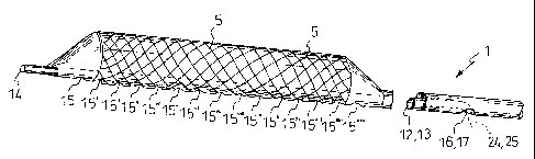
- figure 1 shows a partially sectioned view of
the endolumenal device fitted with a prosthesis;
- figures 2 and 3 show a view from beneath, and a
side view, of a detail of the device of figure 1;
- figures 4 and 4a show the enlarged cross
section on IV-IV of the device of figure 2, according to
two embodiments;
- figure 5 shows an end view along the arrow V of
the endolumenal device of figure 3;
- figures 6a and 6b show a partially sectioned
view of the device of figure 1 during two stages of use;
- figures 7 and 8 show a view from beneath, and a
side view, of a detail of an endolumenal device according
to a second embodiment;
- figure 9 shows the enlarged cross section on
IX-IX of the device of figure 7;
- figure 10 shows a front view along the arrow X
of the device of figure 8;
- figures lla and llb show a partially sectioned
perspective view of the device of figure 7 during two
stages of use;
- figures 12 to 17c show a section through a`T
CA 02399439 2002-08-07
WO 01/60284 PCT/EP00/12964
- 11 -
bifurcation' during eight stages in the deploying of
endolumenal prostheses;
- figures 17d and 17e show in section two
alternative stages in the deploying of prostheses in the
bifurcation shown in figure 17c;
- figures 18 to 23 show a cross portion through a
`Y bifurcation' during six stages in the deploying of
endolumenal prostheses;
- figures 24 and 25 show a view from beneath, and
a side view, of an endolumenal device provided with two
distal ports at the distal end of the body beyond the
prosthesis;
- figure 26 shows an enlarged section on XXVI-
XXVI through the device of figure 24;
- figure 27 shows a view along the arrow XXVII of
the device of figure 25;
- figures 28 and 29 show a view from beneath, and
a side view partially sectioned, of details of an
endolumenal device having a single guidewire lumen
associated to distal ports at the distal end of the body
beyond the prosthesis;
- figure 30 shows a view along the arrow XXX of
the device of figure 29;
- figures 31 and 32 show a view from beneath, and
a side view partially sectioned, of details of an
CA 02399439 2002-08-07
WO 01/60284 PCT/EPOO/12964
- 12 -
endolumenal device having a plurality of guidewire lumens
associated to a plurality of distal ports;
- figures 33 and 34 show a perspective view and a
side view, in partial section, of an endolumenal device
having a single guidewire lumen associated to an apical
distal port and a plurality of distal ports spaced out
along the body;
- figures 35 and 36 show a view from beneath, and
a side view partially sectioned, of details of an
endolumenal device having a first guidewire lumen
associated to an apical distal port and a second
guidewire lumen associated to a plurality of distal ports
spaced out along the body;
- figures 37, 38 and 39 show a view from beneath,
and a side view partially sectioned, and an enlarged
sectioned prospective of details of an endolumenal device
having a fissure suitable for realising a distal port;
- figure 40 shows a perspective view, partially
sectioned, during a stage in the slipping of a guidewire
proximal end into the body fissure of the device of
figure 38;
- figures 41 to 45 show a cross portion through a
vessel during five stages in the deploying of an
embolization containment device and of an endolumenal
prosthesis;
CA 02399439 2002-08-07
WO 01/60284 PCT/EP00/12964
- 13 -
- figure 42c shows a detail in an enlarged scale
of figure 42a;
- figure 42b shows a cross portion through a
vessel during a stages in the deploying of an
embolization containment device according to a further
embodiment;
- figure 46 to 51 show a cross portion through a
bifurcation during six stages in the deploying of
embolization containment devices and of an endolumenal
prosthesis;
- figure 52 shows a cross portion through the
coronary ostium during a stage in the deploying of an
endolumenal prosthesis;
- figure 53 to 55 show a cross portion through a
bifurcation during three stages in the deploying of
endolumenal prostheses by means of two endolumenal
devices reciprocally connected through a guidewire;
- figure 56 shows a perspective view, partially
sectioned, of an endolumenal device wearing a stent
provided with a differentiated spatial behaviour.
With reference to the above figures, the number 1
indicates as a whole an endolumenal device for delivering
and deploying an endolumenal expandable prosthesis, or
balloon catheter. For example, said device is suitable
for deploying an endolumenal expandable prosthesis at a
CA 02399439 2002-08-07
WO 01/60284 PCT/EP00/12964
- 14 -
bifurcation provided with a main conduit and at least a
secondary conduit. The endolumenal device includes an
elongated body 2 having a distal end portion 3 and a
proximal end portion 4. For example, said elongated body
2 is between 100 cm and 160 cm in length, and preferably
between 115 cm and 140 cm. The distal end portion 3
includes expansion means, 5, which can be removably
engaged with an endolumenal expandable prosthesis 6. Said
expansion means 5 can adapt said prosthesis 6 from a
radially collapsed to a radially expanded position, in a
manner which will be described in greater detail below.
The expansion means 5 include a distal portion 7 of the
expansion means a proximal portion 8 of the expansion
means and a central portion 5a of the expansion means to
which the prosthesis 6 can be attached. The distal
portion of the elongated body 3 extends beyond the
expansion means 5 in an apical portion 9. At the proximal
end of the proximal end portion 4 of the elongated body
2, there are means 10 for connecting the endolumenal
device 1 to an apparatus of a type known per se for the
controlled activation of the expansion means 5. The
endolumenal device 1 also includes guidewire tracking
means 11 which extend at least partially along the
elongated body 2. For example, said means 11 extend along
the distal end portion 3 of the elongated body 2 close to
CA 02399439 2002-08-07
WO 01/60284 PCT/EP00/12964
- 15 -
the expansion means, 5 (Figure 1).
Advantageously, the active portion of the
expansion means is longitudinally associated to the
elongated body in order to expand said prosthesis
eccentrically from one side with respect to the elongated
body, in order to leave free from said expanded active
portion the other side of the elongated body.
With further advantage, the guidewire tracking
means 11 comprises at least a guidewire lumen 12 or 13
that at least partially extends inside said elongated
body 2. Said lumen has at least a guidewire distal port
provided on a side of the elongated body opposed to
the expansion means and suitable for slipping through it
a guidewire portion of at least a guidewire placeable
15 with its distal portion in a main or at least a secondary
conduit.
In one embodiment of the invention, a first
guidewire lumen 12 and a second guidewire lumen 13 extend
completely inside the elongated body 2. Distal ports 14,
15 and proximal ports 16, 17 make said first and second
lumens 12, 13 able to receive guidewires 24, 25 (Figure
19).
The distal ports 14, 15 are preferably spaced out
along the elongated body 2. For example, the distal port
14 of the first guidewire lumen 12 is provided at the
CA 02399439 2002-08-07
WO 01/60284 PCT/EPOO/12964
- 16 -
distal end of the apical portion 9, and the distal port
15 of the second guidewire lumen 13 is provided near the
distal end of the expansion means 5 (Figures 1-3, 6a, 6b,
18-23). The proximal ports 16, 17 are preferably
positioned in the portion of the elongated body 2 that
lies between its proximal end and the expansion means 5.
For example, said ports 16, 17 are located at a distance
ranging between 90 cm and 130 cm, and preferably, between
105 cm and 115 cm, from the proximal end, or from the
connector means 10 (Figure 1).
According to one embodiment, said endolumenal
device is a balloon catheter for angioplasty, 1. Said
balloon catheter 1 comprises a tubular catheter 2, a
proximal connector 10, and an inflatable balloon S.
The catheter body 2 is tubular. The proximal
portion 4 of said tubular body 2 is designed to support
and push the distal portion 3. Therefore said proximal
portion 4 is less flexible than the distal portion, which
must be flexible in order to be able to enter the
peripheral branches of a vessel. For example, said
proximal portion 4 is made of a biocompatible material,
such as biomedical steel or nylonTM. Moreover, said
proximal portion 4 is designed to be received in a guide
catheter (not shown and known per se) which is necessary
for maintaining accessibility of the lumen of the vessel
CA 02399439 2002-08-07
WO 01/60284 PCT/EP00/12964
- 17 -
on which it is necessary to operate even when the
endolumenal device 1 is withdrawn. Said guide catheter is
also necessary for introducing, for example, a radio-
opaque contrast medium into the vessel. The proximal
portion 4 of the catheter body, 2 includes an inflation
lumen, 18 (figures 3, 4 and 4a, 6b). Said lumen 18
extends f rom the proximal end of the catheter body 2 to
the inflatable balloon 5.
The proximal connector, 10, for example a
connector commonly known as a "Luer", is provided at the
proximal end of said portion 4 and forms the
abovementioned means of connection of the endolumenal
device 1 to the apparatus for the controlled activation
of the balloon 5. For example, said connector connects
the inflation lumen 18 of the balloon 5 to a pressurized
fluid source.
The balloon 5 is associated with the distal
portion 3 of the catheter body 2 to form an inflation
chamber 19 which at least partially surrounds the
catheter body (figure 3). The inflation chamber 19 is
delimited by a balloon wall 20 equipped with an external
envelope 22. Said inflation chamber 19 is in
communication with the inflation lumen 18. In one
embodiment, the balloon includes, between a distal
portion 7 and a proximal portion 8, a central portion 5a.
CA 02399439 2002-08-07
WO 01/60284 PCT/EP00/12964
- 18 -
Said central portion 5a, when it is in a radially
expanded, or inflated position, is roughly cylindrical.
The balloon wall 20 in one embodiment is non-extendable
or rigid when subjected to pressurized fluid. Therefore
the balloon wall 20, when it is in a radially collapsed
position, is folded around the catheter body 2, for
example it is threefolded or, in other words, forms three
folds 21 (figure 6a). By means of the external envelope
22, the balloon wall 20 can be removably fitted with an
endolumenal prosthesis. For example, the external
envelope is removably fitted with an endovascular stent,
plastically deformable from a radially collapsed
condition to a radially expanded condition, which can be
fixed by pressure to the internal surface of a vessel
wall. For example, said stent is a metallic tubular stent
comprising struts or mesh. For this reason, the diameter
of the central cylindrical portion 5a, when the balloon
is radially expanded or inflated by pressurized fluid
injected through the inflation lumen 18, is such as to
fix said prosthesis to the wall of the vessel by pressure
( f igure 6b).
In a preferred embodiment of the invention, a
longitudinal portion of the balloon wall 20 is associated
internally with the catheter body 2. In other words, said
wall 20 is fixed along its entire length to the catheter
CA 02399439 2002-08-07
WO 01/60284 PCT/EP00/12964
- 19 -
body, so that when the balloon 5 changes from the
radially collapsed or deflated position to the radially
expanded or inflated position, said balloon 5 will extend
eccentrically or asymmetrically with respect to the
catheter body 2, or in other words, on only one side of
the body (Figures 3, 5 and 6b).
The distal portion 7 and the proximal portion 8
of the balloon 5 are advantageously tapered in shape. In
particular, said portions are truncated cones.
Advantageously, the tubular catheter body 2
comprises sheath means or sleeve means 23, for example a
flexible conduit. For example, said sheath means are an
integral part of the elongated body. The sheath means 23
include a tubular body through which run a number of
longitudinal lumens, 12, 13 forming the abovementioned
guidewire lumens. The guidewire lumens 13, 14, or
sections of these, advantageously run in parallel along
the elongated body. Said lumens debouch at the
extremities of the sheath means with the abovementioned
guidewire ports 14, 15, 16, 17. Said sheath means 23 are
located inside the tubular catheter body 2 in such a way
as to leave a space (which forms the abovementioned
inflation lumen 18) along the entire length of that
portion of the catheter body 2 which is situated between
the proximal connector 10 and the balloon 5. Preferably,
CA 02399439 2002-08-07
WO 01/60284 PCT/EP00/12964
- 20 -
said sheath means are attached for their entire length to
the portion of the wall delimiting the balloon inflation
chamber (figures 3, 4, 4a and 6b). In other words, where
the tubular elongated body of the catheter continues in
the balloon wall, said sheath means are associated to a
portion of the balloon wall. In one embodiment, said
sheath means extend beside the balloon distal portion
becoming said catheter body apical portion. The
extremities of the sheath means 23 are attached to the
wall of the catheter body in such a way as to make the
guidewire lumens accessible from outside the catheter
body through the guidewire ports.
It is particularly advantageous when said sheath
means 23 debouch in a first distal guidewire port 14, of
a first guidewire lumen 12, distant from a second distal
guidewire port 15 of a second guidewire lumen 13.
In particular, said sheath means extend to the
tip of the distal portion 3 of the catheter body 2 in
such a way as to debouch with the first distal guidewire
port to the tip of the apical tract 9.
In a first embodiment of the invention, thanks to
the asymmetrical position of the balloon 5 with respect
to the catheter body 2, the second distal guidewire port
15 is positioned along the catheter body 2 so as to allow
the second guidewire lumen 13 to debouch at the distal
CA 02399439 2002-08-07
WO 01/60284 PCT/EP00/12964
- 21 -
end of the central portion 5a of the balloon, or in other
words, so as to be positioned just outside the prosthesis
6 attachable to the balloon 5 (figures 1 to 6b).
In a second embodiment of the invention, the
second distal guidewire port 15 is positioned along the
catheter body in such a way that the second guidewire
lumen 13 debouches at a point located between the distal
portion 7 and the proximal portion 8 of the balloon 5,
and in particular at a point of the central portion 5a
attachable to the prosthesis 6. For example, said port 15
is located near the centre line of said central portion
5a (Figures 7, 8, lla and llb). Preferably, the
prosthesis 6, which can be attached to said catheter 1,
has a window 26 designed to prevent obstruction of said
distal guidewire port 15 when it is fitted on the balloon
5. For example, the prosthesis 6 has a wider cell 26 than
the other cells of the prosthesis, and at the same time
of a size close to that of the ostium of the lumen of the
branch on which it is necessary to proceed, or only
slightly smaller. Alternatively, the balloon can be
fitted with a number of prostheses, placed side by side
in order to avoid obstructing said port 15.
Preferably, the proximal guidewire ports 16, 17
are located in a portion of the catheter body 2 which,
during use of the catheter 1, remains sheathed in the
CA 02399439 2002-08-07
WO 01/60284 PCT/EP00/12964
- 22 -
guide-catheter. For example, said proximal guidewire
ports are located at a distance from the tip of the
catheter ranging between 15 cm and 35 cm and, preferably
between 20 cm and 30 cm. Alternatively, said ports 16, 17
are located at the proximal end of the catheter body. In
this case the balloon catheter 1 is fitted with a
proximal connector 10 with at least two channels. A
channel for the admission of the pressurized fluid into
the inflation lumen 18, and channels for passing the
guidewires 24, 25 along.
Advantageously, radio-opaque markers, 30 and 31
are associated with the catheter body 2 (figure 3). For
example, said markers are located along the catheter body
2 at the distal and proximal ends of the prosthesis 6.
Said catheter body also includes radio-opaque
markers for the identification of the position along said
body of the distal 14, 15, and/or proximal 16, 17
guidewire ports of the guidewire lumens 13, 14.
The subject of the present invention also
comprises a kit for delivering and deploying an
endolumenal expandable prosthesis. Said kit comprises an
endolumenal device, 1, as described above, at least a
couple of guidewires 24, 25, and at least one expandable
prosthesis 6 radially associated with the expansion means
5 of said endolumenal device 1. Said prosthesis comprises
CA 02399439 2002-08-07
WO 01/60284 PCT/EP00/12964
- 23 -
a tubular prosthesis body adaptable from a radially
collapsed condition, of minimal external diameter, to a
radially expanded condition, of extended external
diameter greater than the collapsed external diameter.
For example, said kit for delivering and
deploying an endolumenal expandable prosthesis comprises
at least one first radially expandable prosthesis
associated with the proximal portion of the expansion
means of said endolumenal device and also comprises at
least one second radially expandable prosthesis
associated with the distal portion of the expansion means
of said endolumenal device, or alternatively a single
prosthesis overlapping said proximal and distal portions
of the expansion means.
Each of the guidewires of said kit includes means
of identification, such as for example the colour of at
least a proximal portion of the guidewire, or a diameter
of the cross section of a proximal portion of the
guidewire which differs for each guidewire.
Said guidewires advantageously comprise an
elastically flexible distal end portion.
In particular, said guidewires include initial
proximal sections which are positionable along a proximal
section of path common to all the guidewires, and
secondary distal sections which are positionable along
CA 02399439 2002-08-07
WO 01/60284 PCT/EP00/12964
- 24 -
distal sections of path which diverge and form with said
proximal section of path a bifurcation. It is
particularly advantageous for at least one of said
guidewires to include an elastically flexible distal
portion, which extends at least to straddle said
bifurcation.
it is furthermore advantageous for said
guidewires to include radio-opaque markers, for example
located near the tip of the distal portion.
A description of the working of an endolumenal
device according to this invention follows.
In particular, the procedures necessary for
guiding an endblumenal device along guidewires 24, 25 are
described below. Said guidewires are located along a
common proximal section of path and a diverging distal
section of path, forming a bifurcation between said
sections. The above method comprises the following
stages:
- said endolumenal device is fitted onto a
proximal end of a first guidewire so that said first
guidewire is received in a first guidewire lumen through
its distal guidewire port;
- said endolumenal device is fitted onto a
proximal end of a second guidewire so that said second
guidewire is received in a second guidewire lumen through
CA 02399439 2002-08-07
WO 01/60284 PCT/EP00/12964
- 25 -
its distal guidewire port;
- said endolumenal device is advanced along said
guidewires until at least part of the distal end portion
of the elongated body is positioned beyond the
bifurcation of the guidewires.
Advantageously, it is possible to envisage a
further method of guiding an endolumenal device along
guidewires 24, 25, in which said guidewires are
positioned along a common proximal section of path and a
diverging, distal section of path, forming between said
sections a bifurcation. This further method includes the
following stages:
- said endolumenal device is fitted onto a
proximal end of a first guidewire so that said first
guidewire is received in a first guidewire lumen through
its distal guidewire port;
- said endolumenal device is fitted onto a
proximal end of a second guidewire so that said second
guidewire is received in a second guidewire lumen through
its distal guidewire port;
- said endolumenal device is advanced along said
guidewires until at least part of the distal end portion
of the elongated body lies on a distal divergent section
of path of one of the guidewires.
The steps of a method for fitting radially
CA 02399439 2002-08-07
WO 01/60284 PCTIEPOO/12964
- 26 -
expandable prostheses to the walls of branches forming a
`T bifurcation' 32 are described below (figures 12 to
17e). Said bifurcation 32 comprises a main conduit 33 and
a collateral conduit 34 that branches off from a wall of
the main conduit 33. The abovementioned method comprises
the following steps:
A kit as described above, and in particular a kit
which comprises an endolumenal device having a distal
guidewire port located on a central portion of the
expansion means, is prepared.
Then, through a proximal section of the main
conduit, a first guidewire is positioned in the main
conduit so that it passes the bifurcation, and a second
guidewire is positioned in the collateral conduit. Said
guidewires are positioned in such a way as to follow an
initial proximal section of path together and second
distal sections of path that diverge at said bifurcation
( f igure 12).
Next, a first endolumenal device, equipped with a
radially expandable prosthesis, is fitted onto a proximal
end of the second guidewire, so that said second
guidewire is received in a guidewire lumen of the
endolumenal device, through a distal guidewire port
located on the tip of its elongated body.
Said first endolumenal device is inserted into
CA 02399439 2002-08-07
WO 01/60284 PCT/EPOO/12964
- 27 -
said conduits following the proximal and then the distal
sections of path of the second guidewire in order to
position the radially expandable prosthesis in the
collateral conduit so that its proximal edge is
positioned near an ostium of said collateral conduit
( f igure 13 ) .
Said expandable means are then activated so that
said prosthesis is in its radially expanded condition and
fixed by pressure to the wall of the collateral conduit
(figure 14).
Next, said expansion means are withdrawn and the
first endolumenal device is withdrawn from the second
guidewire until it has been removed from the conduits.
A second endolumenal device equipped with a
radially expandable prosthesis is fitted onto a proximal
end of the first guidewire so that said first guidewire
is received in a first guidewire lumen through its distal
guidewire port located on the tip of the endolumenal
device. Said second endolumenal device is fitted onto a
proximal end of the second guidewire so that said second
guidewire is received in a second guidewire lumen through
its distal guidewire port located on the portion of
elongated body that lies between a distal and a proximal
end of the expansion means.
Said endolumenal device is inserted into the main
CA 02399439 2002-08-07
WO 01/60284 PCT/EP00/12964
- 28 -
conduit and slid along the proximal section of path of
the guidewires until a distal portion of the endolumenal
device, located between the tip of said device and the
distal guidewire port of the second guidewire lumen, is
positioned beyond the bifurcation (figure 16).
The expandable means of said second device are
activated so as to bring said prosthesis into its
radially expanded condition and fixed by pressure to the
wall of the main conduit and straddling the bifurcation
(figure 17a).
Finally said expansion means are withdrawn and
then the second endolumenal device is withdrawn from the
guidewires until it has been removed from the conduits.
Further steps which make it possible to adapt the
previously grafted prostheses in order to cover the
lesion completely are described below.
A third endolumenal device without a prosthesis
is fitted onto the second guidewire, positioning it to
straddle the bifurcation so that a distal portion of the
expansion means enters the collateral conduit and a
proximal portion of the expansion means is positioned in
the main conduit.
The expansion means of the third device are then
activated so as to adapt a portion of the prosthesis in
the main conduit facing the ostium or lateral window of
CA 02399439 2002-08-07
WO 01/60284 PCT/EP00/12964
- 29 -
the collateral conduit to the shape of the lumen of said
collateral conduit (figure 17c).
Said expansion means are withdrawn and then the
third endolumenal device is withdrawn from the second
guidewire until it has been removed from the conduits.
By inflating the third endolumenal device (for
example a balloon catheter for angioplasty) straddling
the bifurcation, the struts of the prosthesis grafted in
the main conduit is moulded so that it surrounds the
ostium of the collateral conduit perfectly, and
guarantees perfect coverage of the lesion area (figure
17c). Alternatively, particularly in the case of larger
diameter or larger bore conduits it is possible to insert
two balloon catheters simultaneously, fitting them on the
guidewires 24, 25, so that they are paired and straddle
the bifurcation, one in the main conduit and the second
partially in the collateral conduit and partially in the
main conduit. Simultaneous expansion of the two balloons
shapes the prostheses so that they match and form a
continuous support structure which covers the entire
extension of the lesion and creates, in the area of the
bifurcation, a funnel-shaped area which joins the main
and the collateral branches and promotes non-vortical
fluid flow in the conduits or vessels.
The stages of the method described above may also
CA 02399439 2002-08-07
WO 01/60284 PCT/EP00/12964
- 30 -
be reversed, grafting first the main vessel and then the
collateral vessel.
In view of the above procedures it is evident
that the grafting of a prosthesis in the main vessel
shifts the plaque 39 material to obstruct the ostium of
the collateral vessel or vice versa (Figure 14). Thanks
to the fact that, using the device according to the
invention, the application of a first prosthesis in a
vessel is always carried out leaving a second guidewire
in a second branch, in spite of the presence in the
ostium of the same of a barrier of plaque caused by
"snow-plow" or "plaque-shifting". It is therefore always
possible to insert in the second branch a device for the
application of a second prosthesis. Using known prior-art
devices it is not possible to operate simultaneously with
two guidewires always present in the two branches of the
bifurcation, because a second guidewire not positioned
inside the prior-art device would be externally jailed by
the prosthesis and rendered unusable. In other words,
with the prior-art device it is necessary to proceed
using only one guidewire per procedural stage. With the
device according to the invention, however, it is
possible to effect the swift exchange of the endolumenal
device on guidewires which always remain in situ, it
being possible to withdraw the endolumenal device from a
CA 02399439 2002-08-07
WO 01/60284 PCTIEPOO/12964
- 31 -
first branch of the bifurcation to reinsert the same
device or a second device in a second branch with extreme
rapidity.
The steps for a further method for fitting
radially expandable prostheses to the walls of the
branches of conduits forming a`Y bifurcation' 35 are
described below. Said bifurcation comprises a proximal
main conduit 36 and a first and a second secondary distal
conduits 37, 38 which branch off from a distal end of the
main conduit, forming between them a carina. Said method
comprises the following steps.
A kit as described above is prepared, and in
particular a kit comprising an endolumenal device fitted
with a distal guidewire port located near the distal edge
of a prosthesis fitted on the expansion means, and a
second distal guidewire port located at the tip of the
device, or apical port.
Through the main conduit first guidewire is
positioned in the first secondary distal conduit and a
second guidewire in the second secondary distal conduit,
said guidewires being positioned so as to follow a first
proximal section of path together and second distal
section of path that diverge after said bifurcation
( f igure 18 ) .
A first endolumenal device equipped with a
CA 02399439 2002-08-07
WO 01/60284 PCT/EP00/12964
- 32 -
radially expandable prosthesis is fitted onto a proximal
end of the first guidewire, so that said first guidewire
is received in a guidewire lumen of the endolumenal
device through its distal guidewire port located at the
tip of its elongated body.
Said first endolumenal device is fitted onto a
proximal end of the second guidewire so that said second
guidewire is received in a second guidewire lumen through
its distal guidewire port located near the prosthesis
distal edge, just beyond the prosthesis.
Said first endolumenal device is inserted into
said conduits following the proximal section of path
until the carina is positioned against the elongated body
and near the distal guidewire port positioned near the
distal end of the expansion means (figure 19).
Said expandable means are activated so as to
bring said prosthesis into its radially expanded
condition, fixed by pressure to the wall of the main
conduit (figure 20).
Said expansion means are withdrawn and the first
endolumenal device is then withdrawn from the guidewires.
A second endolumenal device equipped with a
radially expandable prosthesis is fitted onto a proximal
end of the first guidewire so that said guidewire is
received in a guidewire lumen through its distal
CA 02399439 2002-08-07
WO 01/60284 PCT/EP00/12964
- 33 -
guidewire port located on the tip of said second
endolumenal device.
A third endolumenal device equipped with a
radially expandable prosthesis is fitted, at the same
time as the second endolumenal device, onto a proximal
end of the second guidewire so that said second guidewire
is received in a guidewire lumen through its distal
guidewire port located on the tip of said third
endolumenal device.
Said second and third endolumenal devices are
simultaneously inserted into the main conduit and slid
along the proximal section of path of the guidewires and
then along the respective distal sections of path of said
guidewires, until the expansion means are positioned in a
proximal portion of said first and second secondary
distal conduits, so that a proximal portion of the
expansion means is positioned near the carina. In
particular, care is taken to ensure that the proximal
edge of both the second and third prostheses is in
contact with the distal edge of the first prosthesis,
already positioned and expanded in the main lumen (figure
21).
The expansion means of said second and third
endolumenal devices are activated in order to bring the
respective prostheses into a radially expanded condition
CA 02399439 2002-08-07
WO 01/60284 PCT/EP00/12964
- 34 -
fixed by pressure to the walls of said first and second
distal conduits (figure 22).
Said expansion means are withdrawn and then the
second and third endolumenal devices are withdrawn from
the guidewires until they have been removed from the
conduits (figure 23).
The above description shows how the use of at
least two guidewire lumens which extend at least
partially along the inside of the elongated body makes it
possible to fit the endolumenal device simultaneously on
at least two guidewires. In this manner, once at least
two guidewires have been inserted in the branches of a
bifurcation, it will be possible to insert and withdraw
the endolumenal device from a first branch of the
bifurcation without ever loosing rapid access to all the
branches already negotiated, i.e. reached by guidewires.
In other words, it will be possible to maintain
uninterrupted access or vascular approach to all the
branches of the vascular system on which it is necessary
to operate and in which a guidewire has been inserted or,
in yet other words, using the device proposed it is no
longer necessary to break through the barrier of plaque
39 material which obstructs the ostium of the branch by
"snow-plow" or "plaque-shifting".
Thanks to the endolumenal device according to the
CA 02399439 2002-08-07
WO 01/60284 PCT/EP00/12964
- 35 -
invention it will also be possible to position accurately
a first endovascular prosthesis in the main vessel always
with precise positioning and complete distension or
application of the prosthesis over the entire area of the
lesion, thus reducing the probability of re-stenosis and
avoiding the pitfalls of the known techniques.
Advantageously, the endolumenal device proposed
allows extreme flexibility and modularity in the
application of the endolumenal prostheses. Thus, if the
expansion means are positioned exactly straddling the
bifurcation it is possible to deploy endolumenal
prostheses of exactly the correct length and diameter for
the dimensions of the segment of damaged vessel to be
treated, by means of the proximal and distal portions of
the expansion means.
With further advantage, each portion of the
expansion means makes it possible to graft a number of
endolumenal prostheses of optimal diameter and length for
the anatomy of the damaged vascular branch.
When expansion means fitted to the endolumenal
prostheses are in the collapsed position, the device
according to the invention is of reduced transverse bulk,
making it possible to reach peripheral branches extremely
easily and rapidly (trackability).
Together with the versatility of application of
CA 02399439 2002-08-07
WO 01/60284 PCT/EP00/12964
- 36 -
prostheses adapted to different branches of the
bifurcation, the device proposed also makes it possible
to join prostheses, or, in other words, it allows total
coverage of the damaged area, avoiding prolapse of
atheromatous material and reducing the probability of re-
stenosis.
A further advantage derives from the fact that,
using the endolumenal device according to the invention,
the geometry of the prosthesis is not distorted and the
vascular anatomy is respected. In contrast, distortion of
the prosthesis is inevitable when endolumenal devices
according to the prior art are used.
Obviously, variations and/or additions to what is
described above and illustrated may be envisaged.
Alternatively to a balloon with rigid walls
threefolded onto the catheter body for insertion into the
lumen of a vessel, as described above, it is possible to
envisage the use of a compliant or extensible balloon.
Other possible variations are:
- the catheter of the type described above,
"single-operator rapid exchange" or "monorail", may
alternatively be of the "over-the-wire" type, that is
with opening of the proximal guidewire lumens at the
proximal end of the elongated body;
- one of the at least two guidewire lumens may
CA 02399439 2002-08-07
WO 01/60284 PCT/EP00/12964
- 37 -
always be occupied by a guidewire and may be inserted in
the conduit, or vessel, together with the endolumenal
device. Preferably, in this case the guidewire is
fastened to or an integral part of the elongated body of
the endolumenal device, for example extending from the
apical portion of this ("fixed-wire").
- the catheter may also be of the perfusion
balloon type in which passages are provided for fluid
flow when the balloon is inflated: these provide
communication between the portions of elongated body
above and below the expansion means (passages for the
blood in the body to prevent temporary occlusion of the
vessel during the application of the prosthesis and the
inflation of the balloon).
- The endovascular prosthesis may be modular. For
example it is possible to provide a series of prostheses
of set diameters and a series of set lengths which the
operator can crimp to the proximal and distal portions of
the expansion means, making them extremely flexible or,
in other words, making it possible to adapt the
prosthesis perfectly to the pathological requirements of
the moment, or in other words, to the size of the lesion
and the bore of the lumen of the vessel on which it is
necessary to operate.
As an alternative to the above description,
CA 02399439 2002-08-07
WO 01/60284 PCT/EP00/12964
- 38 -
illustrated by figures 3 and 8, at least one portion of
said at least a couple of guidewire lumens 12, 13 forms a
single guidewire lumen (figures 28, 29, 30, 33 and 34).
In a further variation of the invention, a
guidewire lumen 13 have distal ports 15 located near the
proximal end of the expansion means, 5. Instead of the
embodiment illustrated, for example, in Figures 2 or 3,
the elongated body is attached externally to the wall of
the balloon.
In a further embodiment of the invention, said
expansion means are designed to hold a self-expanding
prosthesis in a radially folded position and release it
in a controlled manner so that it takes up a radially
expanded position. Said expansion means include a sheath
designed to receive in a sheath lumen said self-expanding
prosthesis. Said sheath can advantageously be adapted in
controlled manner from a first constricted position in
which the self-expanding prosthesis is confined in said
lumen of the sheath, to a second released position, in
which said prosthesis is released from said lumen of the
sheath so that said prosthesis is radially free, to bring
itself into the radially expanded condition.
Such a device can be advantageously used in the
artificial conduits of biomedical equipment that connects
up to the patient's body. For example, a device of the
CA 02399439 2002-08-07
WO 01/60284 PCT/EP00/12964
- 39 -
type described above can be used for transporting,
positioning and deploying an element for the repair of
the walls of a conduit accidentally damaged during the
use of the abovementioned machinery.
Advantageously, the endolumenal device 1
comprises at least a guidewire lumen 12 or 13 extended
completely inside the elongated body 2.
With further advantage, the active portion of the
expansion means is entirely associated to the elongated
body in order to expand said prosthesis exclusively from
one side with respect to the elongated body, and in order
to leave free from said expanded active portion the other
side of the elongated body.
According to one embodiment, the side of the
elongated body portion associated to the expansion means
and free from said expanded active portion, or free side,
is provided with a fissure 100 suitable for realizing a
distal guidewire port 15 of the at least a guidewire
lumen 12, 13. It is furthermore advantageous for said
fissure 100 to be extended between the distal end and the
proximal end of the elongated body portion associated to
the expansion means 5 (figures 37, 38 and 39).
Preferably, the side of the elongated body
associated to the expansion means 5 and free from the
expanded expansion means comprises a wall 105 that
CA 02399439 2002-08-07
WO 01/60284 PCT/EP00/12964
- 40 -
partially binds said at least a guidewire lumen 12,13.
Said wall 105 is suitable for being bored by a guidewire
end 106, for example the proximal end, in order to slip
said guidewire 24 through the bored portion of the wall
105 (Fig. 40).
According to a further embodiment, the at least a
guidewire lumen 12 and/or 13 of the tracking means has a
plurality of distal guidewire ports 14, 15,
151, 151I, 15=II 152" and/or 15 , 15 1, 15 11, 15 11I 151X, 15X, 15X1 10
15XII, 15XIII, 15X1 spaced out along said elongated body 2
(figures 31, 32, 33, 34, 35 and 36).
Preferably, the guidewire tracking means 11
comprises a plurality of guidewire lumens 12,
13, 131, 131I, 131II ssociated to each of said distal
guidewire ports 14, 15, 151, 151I1151=i, 151v (figures 31, 32) .
Advantageously, the at least a guidewire lumen 12
and/or 13 has a distal guidewire port 14, or apical port,
at the tip of said distal end portion 3 of the elongated
body 2 (figures 31, 32, 33, 34, 35 and 36).
With further advantage, a first guidewire lumen
12 associated to said apical port 14 is provided in the
body and a second guidewire lumen 13 is associated to a
plurality of distal guidewire ports 15, 151, 151I, 151II, 151";
15 , 15 1, 15911 15 11I, 151X, 15X, 15XI, 15XII, 15XIII, 15x=v or side
ports, provided on a side of the elongated body opposite
CA 02399439 2002-08-07
WO 01/60284 PCT/EP00/12964
- 41 -
the expansion means (figures 35 and 36).
As an extremely advantageous alternative, a
single guidewire lumen 12, 13 associated to said apical
port 14 is provided in the body and is also associated to
a plurality of distal guidewire ports
15,151,1511,151I1,151 ;15v,15 1,15 11,15'11,151X,15X,15XI,15X11 15XII= 15X1
or side ports, provided on a side of the
elongated body opposed to the expansion means (figures 33
and 34).
In a further variation of the invention, the at
least a guidewire lumen 13 has a distal guidewire port 15
near a distal end of the expansion means 5.
Advantageously, the at least a guidewire lumen 13
has at least a distal port 15, 151, 151I, 151II 151 ; 15v, 15vi
in a portion of
15 11, 15 11I, 151X, 15X, 15XI, 15XII, 15XIII, 15XIv
the elongated body 2 that lies between a distal end and a
proximal end of the expansion means 5.
In a further variation of the invention, the
endolumenal device can be advantageously used in order to
improve maneuvrability and clinical efficacy of some
embolization containment devices (ECD) during coronary
angioplasty and stenting.
Actually, a frequent complication of these
procedures is the so called "no-flow phenomenon",
consisting of impairment of the blood to flow down to the
CA 02399439 2002-08-07
WO 01/60284 PCT/EP00/12964
- 42 -
distal vessels, even though the obstruction has been
removed.
This calamitous event is mainly caused by the
distal embolization of the thrombus debris, and arterial
spasms induced by some vaso-constrictive substances
released into the blood stream because of the plaque
crumbling and compression during balloon inflation.
These events are frequent when treating recent
coronary occlusions in acute myocardial infarction, or
when treating coronary lesions with angiographic
evidence of a thrombus within the lumen, as in unstable
angina.
Therefore, in addition to bifurcated lesion
treatment, the proposed device will find large scale
application in the situations as described here
following.
Most ECD currently in use take the form of an
occluding balloon 102 (figure 42b), or of a basket-shaped
or an umbrella-shaped device 101 (figure 42c), which
necessarily blocks the flow distally of debris, and
substances which can cause vasospasms.
An example of such application is described with
the following steps:
Step 1- a conventional guidewire (cGW) 24 is
advanced beyond the occlusion as a "trailblazer" for the
CA 02399439 2002-08-07
WO 01/60284 PCT/EP00/12964
- 43 -
ECD 101. In fact, these devices have less maneuvrability
and are more fragile than cGW 24 and, therefore, can't be
used to bore, and to cross an occlusive thrombus (figure
41).
Step 2- the ECD 101 is positioned as proximal as
possible, but sufficiently distant to permit the
entrapment of the embolic material and to allow easy
handling and positioning of a stent-delivery system, and
finally, stent deployment. Furthermore, positioning must
be without excessive advancement of the ECD which would
allow embolic material to escape into lateral branches
34, if positioned beyond vessel bifurcations.
Step 3- the ECD 101 is activated (i.e., the
"umbrella" is opened or the "balloon" inflated), after
which the cGW is withdrawn, in order to avoid its jailing
between the stent and the vessel wall after stent
deployment (figure 42a).
Step 4- a conventional stent-delivery system is
advanced using the ECD 101 as a guidewire (figure 43).
Step 5- the stent-delivery system is inflated
and the stent deployed (figure 44).
Step 6- debris and vasospastic substances,
released during the stenting procedure, and entrapped by
the ECD, are removed: with suction using a dedicated
probe which has been advanced until it is contiguous with
CA 02399439 2002-08-07
WO 01/60284 PCT/EP00/12964
- 44 -
the occlusive "balloon", or withdrawn within the
"umbrella", after its closure (figure 45).
As clearly described, this technique presents
some drawbacks:
- ECD 101, used as guidewire, give low support to the
delivery systems especially when they are positioned
very proximally;
- a guidewire 24 repositioning could be needed after the
stent deployment because of procedural complications
(such as dissections) or in order to treat other
lesions which come to light only after they has been re-
opened. This procedure takes time and can be hazardous
and unsuccessftil.
Therefore, leaving the guidewire 24 for the
duration of the procedure would be preferable.
All of this is easily performed with the proposed
device 1 which allows to ride both a cGW 24 (represented
with a broken line in figures 43, 44 and 45) and a ECD
101 or 102 simultaneously, utilizing the apical port 14
and a lateral or side port 15 provided on a side of the
elongated body of the expansion means 5 (figures 35,36).
Therefore, we can leave a distally positioned
cGW 24 for the duration of the procedure, as an
"auxiliary wire" to give more support to the delivery
system and to avoid re-crossing the stented lesion,
CA 02399439 2002-08-07
WO 01/60284 PCT/EP00/12964
- 45 -
should this become necessary.
This proposed device also offers a significant
clinical advantage in the treatment of a thrombotic
occlusion involving the ostium of a branch, or just
proximal to a vessel bifurcation (very frequent cases),
as shown in the following steps:
Step 1- the occlusion is crossed using a cGW 24
as a "trailblazer" (Figure 46);
Step 2 - a first ECD 101 is advanced into a first
branch 37 (Fig. 47);
step 3 - a second ECD 101 is advanced into a
second branch 38, and both ECD are activated after the
cGW 24 withdrawal (Fig. 48);
step 4 - the proposed stent-delivery device 1 is
advanced and positioned with the simultaneous use of both
ECD's as guidewires (Fig. 49);
step 5 - the stent is deployed and the vessel
patency and the blood flow restored (Fig. 50);
step 6 - the debris and any substance released
during the procedure, entrapped by the 2 ECD's, are
finally removed (Fig. 51).
Further clinical condition, where the device is
extremely useful, is in an ostial lesion at the origin of
the right coronary artery or a saphenous graft. In this
case the engagement of a guidecatheter 103 is impossible
CA 02399439 2002-08-07
WO 01/60284 PCT/EPOO/12964
- 46 -
due to the narrowing of the lumen. Therefore the
guidecatheter 103 is positioned free in the middle of the
aortic lumen, opposite the ostium, where there are a
continual cardiac-cycle related movements of both the
guidecatheter 103 and the delivery system 1.
In such circumstances the stent positioning and
deployment, using the known devices, is necessarily
imprecise and may improperly be implanted, or may be the
cause of failure of the procedure. So, often times, these
clinical situations are referred to surgeon for aorto-
coronary bypass grafting.
Utilising the proposed device 1, it is possible
to attain a precise positioning and deployment. The
proposed method comprises: positioning of a first
guidewire 24 in the diseased vessel suitable to fit it in
the apical port 14 of a proposed device guidewire lumen;
then positioning of a second guidewire 25 free in the
aortic lumen and fitting said free guidewire in a
proposed device side port 15"1 , just proximal to a stent
6 crimped down on the delivery system. In this way, the
proposed device 1 can be advanced in the right coronary
artery until the emerging second guidewire 25 blocks the
delivery system with the proximal edge of the stent 6
perfectly aligned with the aortic wall. By maintaining a
constant, even push until the stent delivery system
CA 02399439 2002-08-07
WO 01/60284 PCT/EP00/12964
- 47 -
(balloon) is activated (inflated), it is possible to
attain a stable positioning within the ostial lesion and,
therefore, the proper deployment of a stent.
A further method of employment of the proposed
device is in the stenting of bifurcated lesions, where
the proposed device 1 allows the operator to implant
simultaneously two stents 61 and 61I, perfectly flanked
with their proximal edges on the same level, utilizing a
known "V" or "kissing" technique.
After having positioned guidewires 24, 25 in the
respective branches 37 and 38, a first guidewire 24 is
fitted in a first device through its apical port 14.
The same guidewire exits the device through a
side port 15X=v, proximal to the stent, and the first
device is then advanced in the first branch 37 (figure
53).
A second guidewire 25 is received in a second
device through its apical port 14. The first guidewire
24, received in the first device, is subsequently fitted
in the second device through its side port 15"I" proximal
to the stent (figure 54).
This second device is then advanced until it is
"automatically" blocked when its side port 15"I" arrives
at vessel bifurcation, where the two guidewires 24, 25
diverge. With a gentle pulling back of the first device,
CA 02399439 2002-08-07
WO 01/60284 PCT/EP00/12964
- 48 -
the respective side ports 15X1 will be perfectly aligned
and held in position by the first guidewire 24, which
exits the first device and re-enters the second device.
In this way, the stents 61 and 61I, mounted on two
devices will necessarily be positioned with the proximal
stent edges at the same level and with a complete
coverage of the vascular "carina" between the two
branches (Fig. 55).
Contrary to the "V" and "kissing" technique used
with traditional balloons, the proposed device allows an
"automatic" and precise positioning of paired stents,
avoiding approximations, or that one of the two delivery
systems is dislodged by the other during inflation of the
balloons.
The proposed method of deployment is extremely
efficient, particularly if employed subsequently a
preliminary deployment of a stent 6 in the parent vessel,
just proximal to the bifurcation; or implanting in the
two branches dedicated stents having proximal-angled
edges. In this way the coverage of the lesion is
improved, avoiding overlapping of the stents, and with a
complete coverage of the plaque (figure 55).
It is a further advantage that the proposed
device has the possibility to rotate in a controlled
manner along its longitudinal axis. In this way it is
CA 02399439 2002-08-07
WO 01/60284 PCT/EPOO/12964
- 49 -
possible to properly orient and deploy stents. Thus, even
without a bifurcated lesion, with a guidewire 24
previously deployed in a side-branch (i.e. in a septal or
diagonal branch) it is possible to implant dedicated
stents 103 with variable structures along their
circumference (i.e.: struts 104, 105 of variable widths
or with different drug coatings 106, and cells, with
different diameter or dimensions, provided in different
region of the stent) thereby allowing a specific
treatment of selected areas in a single lesion.
A person skilled in the art could make numerous
changes and adaptations to the preferred embodiment of
the endolumenal device described above or substitute
elements with others functionally equivalent, in order to
meet contingent and specific requirements, without
however departing from the scope of the following claims.