Note : Les descriptions sont présentées dans la langue officielle dans laquelle elles ont été soumises.
CA 02399952 2002-08-13
WO 01/60637 PCT/US01/03117
1
DESCRIPTION
QUICK CHANGE WHEEL SYSTEM FOR A CAMERA DOLLY
BACKGROUND OF THE INVENTION
The field of the invention is camera dollies. More specifically, the
application relates
to a system for allowing quick change of wheels on a camera dolly.
In motion picture or video filming, cameras are often supported on camera
dollies, so
that camera lens positions, angles, and elevations may be smoothly and easily
achieved
without interruption. Most camera dollies are pushed by "dolly grips" or
camera dolly
operators. For use on a relatively smooth and hard surface, such as on a sound
stage, or other
indoor set, the camera dolly is preferably provided with solid tires having
relative high
hardness, to reduce rolling friction, and make it easier to push and maneuver
the camera
dolly. For use on more irregular, surfaces, for example an indoor surface
having small
cracks, bumps, etc., a softer solid tire is preferred, to absorb shock
impulses, albeit ~,vith a
small increase in rolling friction. For use on still more irregular surfaces,
pneumatic tires are
typically used, to provide a higher degree of shock absorption, although with
a slightly
greater increase in rolling friction. For use on unpaved surfaces, such as
grass, sand, etc., or
in other applications where a maximum level of smoothness in dolly movement is
required,
dolly track is laid down, with the dolly wheels rolling on the smooth metal
rails of the track.
Having a smooth rolling surface, or a way to absorb the shock impacts created
when rolling
over an irregular surface, is important, as shock impacts generated via the
rolling movement
of the camera dolly wheels can cause unacceptable movement of the camera lens
during
filming, resulting in unsteady recorded images.
It is frequently necessary to change the wheels on the camera dolly, to
compensate for
change in the ground conditions. For example, if a first part of a film
sequence takes place
indoors, the hard solid wheels may be used. Then, if the sequence continues
outdoors, it may
then be necessary to change over to a pneumatic or track wheel. While a
combined track/
pneumatic wheel, as described in U.S. Patent No. 4,943,101, has been
successfully used in
the past, to avoid to wheel changeover when switching between track and
pneumatic wheels,
it remains necessary to change wheels when the harder solid wheels are needed.
Wheel changeover has conventionally required time and tools. Typically, a
screwdriver or wrench is needed to remove a fastener from an axle to remove,
and then
CA 02399952 2002-08-13
WO 01/60637 PCT/US01/03117
2
reinstall, a wheel. As most camera dollies have one pair of wheels at each
corner, for a total
of eight wheels, wheel changeover can be time consuming. Typically, changing
over each
wheel, even for a skilled camera dolly grip, requires e.g., 60-80 seconds, so
that changing
over eight wheels typically takes about 10 minutes. While in most endeavors,
ten minutes
may be acceptable, motion picture production often requires a large number of
highly skilled
professionals, and extensive amounts of equipment and supplies, so that
production costs are
extremely high. Accordingly, saving even a few minutes in production time is
highly
significant, in terms of production costs. Moreover, in sequences involving
fast changing
lighting conditions, the ability to film the sequence as desired may depend on
how quickly
the equipment, including the camera dolly, can be set up.
Accordingly, there remains a need for designs which allow fast changeover of
camera
dolly wheels.
BRIEF STATEMENT OF THE INVENTION
In a first aspect of the invention, a camera dolly has a plurality of axles
connected
directly or indirectly to a camera dolly chassis. The camera dolly wheels are
secured onto
the axles by quick release clip assemblies. The clip assemblies can be quickly
and easily
removed and reinstalled, by hand and without tools, to allow fast wheel
changeover.
Preferably, a cap is attached to each of the axles, and the quick release
clip' has a
spring which engages the cap. The clip is released by pulling the spring away
from the
cap, and sliding the clip off of the axle.
In a second aspect of the invention, the release clip has a U-shaped frame
having
bosses extending outwardly from a land area. The cap preferably has a shaft, a
shoulder,
and a top surface. The U-shaped frame is advantageously engageable around the
cap, with
the shoulder of the cap against the land area of the U-shaped frame.
In a third aspect of the invention, the axles of the camera dolly have a
diameter
equal to or greater than the diameter of the cap, so that the wheels can be
removed from
the axles, after the quick release clip is removed, but without removing the
cap.
In a fourth aspect of the invention, in a method for wheel changeover in a
camera
dolly, a second wheel of the camera dolly is rolled up onto a wedge, so that a
first wheel of
the camera dolly is lifted off of the ground. A quick release clip holding the
first wheel
onto the first axle is released and removed. The first wheel is removed and
replaced with
CA 02399952 2007-11-08
79102-43
3
another wheel, and the clip reinstalled. Use of the ramp
avoids the need to lift the wheels off the floor to achieve
wheel changeover.
According to another aspect of the present
invention, there is provided a camera dolly comprising: a
chassis; a plurality of axles connected directly or
indirectly to the chassis; a wheel on each of the axles; and
a quick release clip assembly on each of the axles, the
quick release clips holding the wheels onto the axles, and
removable from the axles without tools.
According to still another aspect of the present
invention, there is provided a quick release wheel kit for a
camera dolly having a plurality of axles, and with a wheel
on each axle, comprising: a cap adapted to be attached to
an axle on the dolly with a fastener; a quick release clip
attachable onto and removable from the axle without using a
tool; and a wedge for lifting a wheel off of the ground.
According to yet another aspect of the present
invention, there is provided a quick release clip assembly
for allowing a quick changeover of a wheel on a camera
dolly, comprising: a quick release clip having a frame
having an open end and a closed end; and a spring attached
to the frame and having bridge section extending across and
biased against the open end of the frame; and a cap having a
shoulder and a shaft section, with the shaft section
engageable into the open end of the frame, and with the
bridge section of the spring engageable over shoulder of the
cap.
According to a further aspect of the present
invention, there is provided a method for changing a wheel
on a camera dolly comprising the steps of: rolling a second
wheel of a camera dolly up onto a wedge, so that a first
CA 02399952 2007-11-08
79102-43
3a
wheel*of the camera dolly, on a first axle of the camera
dolly, is lifted off of the ground; releasing and removing a
quick release clip from the first axle; removing the first
wheel from the first axle; installing a replacement wheel
onto the first axle; installing the quick release clip back
onto the first axle, with the quick release clip holding the
replacement wheel onto the first axle; and rolling the
second wheel of the camera dolly off of the wedge.
Accordingly, it is an object of an embodiment of
the invention to provide a fast wheel changeover system for
a camera dolly. The invention resides as well in
subcombinations of the features described.
BRIEF DESCRIPTION OF THE DRAWINGS
In the drawings, wherein the same reference number
indicates the same element throughout the several views:
Fig. 1 is a perspective view of a camera dolly.
Fig. 2 is a perspective view of a kingpin and
retaining washer of a prior art camera dolly.
Fig. 3 is a front view of the present quick
release clip.
Fig. 4 is a side view thereof, in part section.
Fig. 5A is a front view of the clip shown in
Figs. 3 and 4 installed on the kingpin shown in Fig. 2.
Fig. 5B is a perspective view thereof.
Fig. 6 is a perspective view of the kingpin shown
in Figs. 2 and 5, with the clip and wheel shown in Fig. 5
removed, and with the remaining wheel positioned on a wedge.
CA 02399952 2007-11-08
79102-43
3b
Fig. 7 is a plane view of the wedge shown in
Fig. 6.
Fig. 8 is a side view thereof.
Fig. 9 is a perspective view of a wheel and wedge
carrying assembly.
DETAILED DESCRIPTION OF THE DRAWINGS
Turning now in detail to the drawings, as shown in
Fig. 1, a camera dolly 30 has an arm 34 attached to a
chassis 32. A platform 38 on the arm 34 supports a
camera 36. The dolly 30 has wheels 48 rotatably attached to
a kingpin 46, at each corner of the chassis 32. The
kingpins 46 may be attached directly to the chassis 32, or
they may be attached to legs 40, with the legs 40 pivotably
attached to the chassis 32 of the dolly 30, as shown in
Fig. 1. A steering bar 44 steers the wheels 48, by turning
the kingpins 46 to appropriate angles, as described, for
example, in U.S. Patent No. 6,135,465.
Referring to Figs. 1 and 2, the wheels 48 have
captured bearings 50. When installed, the inner race of the
bearing 50 slides over the axle 60 extending outwardly from
CA 02399952 2007-11-08
79102-43
4
the kingpin 46. A fastener 64 extends through a counter sunk retaining washer
and threads
into an axle hole 62. In this design, the retaining washer 63 holds the wheel
48 onto the
axle 60, and the fastener 64 holds the retaining washer in place. To change
the wheel 48,
the fastener 64 must be removed, using a tool. The wheel to be removed must
also be
lifted off the ground, to remove it from the axle 60, even after the screw 64
and retaining
washer 63 have been removed. Thus, significant time and effort is required,
even for two
people, to changeover all eight wheels.
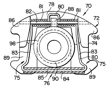
A fast wheel changeover system includes a quick release clip 70 and a cap 90
as
shown in Figs. 3 and 4. The clip 70 has a U-shaped frame 72. Grip surfaces 74
are
provided on the outside of the legs 75 of the U-shaped frame 72. A spring 80
is attached
to the top or closed end 78 of the U-shaped frame 72. The spring 80 has a coil
section 81
joined to bridge section 85 via spring leg sections 83. A spring pin 82
extends through the
coil sections 83, through a center boss 88, and into side bosses 86. A tube 84
is placed on
the bridge section 85 of the spring 80.
- Referring still to Figs. 3 and 4, the center boss 88 and side bosses 86
extend
upwardly or outwardly on the U-shaped frame 72 from a land area 89 formed on
the legs
75. Consequently, as shown in Fig. 4 the leg sections 83 and bridge section 85
of the
spring .80 lay substantially flat and parallel to the flat back surface 73 of
the U-shaped
frame 72. The bridge section 85 of the spring 80 is biased downwardly against
the land
area 89 on the legs 75.
A cap 90, shown in cross-hatch section in Fig. 4, has a counter sunk opening
92, an
annular shoulder 94, and a shaft section 96. With the cap 90 installed into
the clip 70, as
shown in Fig. 4, the top or outer surface 98 of the cap is substantially flush
with the top or
outside surfaces of the bosses 86 and 88.
Use of the cap 90 is preferred, as it allows existing camera dollies, such as
shown
in Fig. 1, to be retrofitted for use with the quick release clip system shown
in Figs. 3 and 4.
This retrofit or conversion is made by removing the screw 64, discarding the
retaining
washer 63, and replacing it with the cap 90. Alternatively, the cap 90 can be
machined or
formed directly as part of the axle 60. The retrofit of a dolly 30 from the
design shown in
Fig. 2 to the design shown in Figs. 3 and 4, does not require any changes to
the ar:le 60.
Referring to Figs. 3, 4, 5A, 5B and 6, in use, the cap 90 is attached to the
end of the
axle 60 by threading the screw or fastener 64 through the counter sunk opening
92 and
into the threaded axle hole 62. Referring to Fig. 4, the diameter of the axle
60 is equal to,
CA 02399952 2002-08-13
WO 01/60637 PCT/US01/03117
or greater than the diameter D of the annular shoulder 94. Consequently, the
bearing 50 of
the whee148, which slides onto the axle 60, can pass over the annular shoulder
94, without
removing the cap 90. Accordingly, preferably, a cap 90 is attached onto the
end of each
axle 60 and remains in place on the axle.
5 The ergonomically designed U-shaped clip can be easily installed by placing
fingers in the grip surfaces 74 and by first pushing the clip in against the
cap, to extend the
spring, and then moving the clip downwardly, until the spring locks into
position against
the land area 89. This is a fast and simple operation, easily performed with
one hand, as a
result of the U-shaped clip. This installation is also easily performed even
when the axle
is recessed in a wheel well of the wheel. As shown in Fig. 5B, with the clip
70 installed,
the tube 84 is against the outside surface 95 of the cap 90 (and tangent to
the centerline of
the cap.). As the closed end 78 of the clip frame 72 comes to rest against the
shaft section
96, the tube 84 on the spring 80 clears the top surface 98 of the cap 90 and
moves back
down onto the land area 89 of the legs 75.
The clip 70 can then not be pulled .axially (in the direction of the arrow A
in Fig.
4), as the land area 89 of the legs 75 is captured between the annular
shoulder 94 of the
cap 90, and the end of the axle 60. The clip 70 also cannot be removed from
the axle 60 in
radial direction (in the direction of the arrow R or R' in Fig. 4), because
the closed end 78
of the clip 70 is stopped by the shaft section 96 of the cap 90, and because
the tube 84 on
the bridge section 85 of the spring 80 rests against the outside surface 95 of
the annular
shoulder 94. As a result, the clip 70 holds the wheel 48 onto the axle 60 with
the same
effectiveness as the screw 64 and retaining washer 63 shown in Fig. 2.
However, the clip
70 is very quickly removed, without tools, by simply placing a finger in the
open end 76 of
the clip frame 72, behind the tube 84, and pulling the tube 84 away from the
land area 89
of the legs 75, so that the tube 84 clears the side surface 95 of the shoulder
94. The clip 70
can then be pulled off the axle 60 in the radial direction R.
Turning to Figs. 6-9, a wedge 100 is advantageously used to lift wheels of the
dolly
off the ground, to allow them to be changed over. The wedge 100 has wedge-
shaped or
angular ends 102 on either side of wheel recess 104. A through hole 106 passes
through
the center of the wheel recess.
In use, either wheel of the wheel pairs at each corner of the dolly, as shown
in Fig.
1, is rolled up onto the wheel recess 104 of the wedge 100. This causes the
other wheel of
that pair to be lifted off of the ground, so that it can be easily changed
over via use of the
CA 02399952 2002-08-13
WO 01/60637 PCT/US01/03117
6
clip 70 and cap 90, as described above. The procedure is then repeated for the
wheel on
the other side. Use of the wedge 100 avoids the need for lifting any of the
wheels off of
the ground. Consequently, the wheel changeover, using the wedge 100 can be
easily
performed with only one person.
To further speed up wheel changeover, up to four wedges 100 may be used. For
example, by aligning a wedge 100 with each of the inside wheels of the four
wheel pairs
and then pushing the dolly 30 up onto the wedges 100, the four outer wheels
are
simultaneously lifted off of the ground and can be changed over. After the
outer wheels
have been changed over, the procedure is repeated for the inside wheels (with
or without
using the dolly steering system to move the inside wheels to the outside and
vice versa).
Thus, all eight wheels can be changed over with only two movements of the
dolly 30, the
first to lift the outside wheels, and the second to lift the inside wheels. Of
course, other
wedge configurations and numbers of wedges may be used. The wheel changeover
procedure described above can reduce wheel changeover time, by about half.
Referring to Fig. 9, a wheel carrier has a threaded post 114 extending
vertically
upwardly from a base plate 112. Wheels 48 are placed over the post 114. Wedges
(two in
the embodiment shown) are placed on top of the wheels, with the post 114
extending
through the holes 106. A handle 116 is then threaded onto the post 114 to
secure the
wedges 100 and wheels together. The wheel carrier 110 thus provides a
convenient and
easily accessible way of storing and transporting a changeover wheel set for
the camera
dolly 30, as well as wedges 100.