Note : Les descriptions sont présentées dans la langue officielle dans laquelle elles ont été soumises.
DESCRIPTION
DRILL BIT
(TECHNICAL FIELD)
The present invention relates to a drill bit that includes a cemented carbide
cutting
blade tip united tightly to a bit body leading end of the drill bit by brazing
or other
welding technique. More particularly, this invention relates to a drill bit
adapted to drill
a hole in materials such as concrete, stone, and so forth.
[BACKGROUND ART]
In drilling holes in materials such as concrete and stone, a special drill bit
is
attached to a rotary hammer drilling machine, and cutting by rotation and
drilling by
action of simultaneous application of a vibrational striking force in axial
direction and a
rotational torque is carned out. And, in order to meet the demand for higher
efficiency
in such a type of drilling work, drill bits of the type having a cutting blade
tip of
cemented carbide superior in resistance to abrasion which is united tightly to
a leading
end side of a bit body of the drill bit by brazing, welding, or the like, have
been used
extensively. For example, Japanese Patent Kokai Publication No. H07-180463
discloses one such cutting blade tip being provided at a bit body leading end.
The
cutting blade tip is rectangular in cross section. Main cutting edges are
formed along
one diagonal of the rectangle, whereas auxiliary cutting edges are formed
along the
other diagonal. The two main cutting edges arranged symmetrically with the
shaft
center are connected together in a continuous manner so as to form a chisel
edge at the
top thereof.
CA 02402142 2002-09-05
2
However, drilling (cutting) a hole with conventional drill has the following
drawbacks.
That is, with respect to drilling by means of a drilling machine, the drill
fatefully
has flexural and torsional rigidity limitations, and the resulting drill hole
has accuracy
limitations. Further, the drill has, at its cutting blade tip central portion,
a chisel edge.
Therefore, when the drill leading end is subjected to cutting resistance
during drilling
operation, the drill is placed in such a state that it becomes relatively
flexible and, as a
result, each end of the chisel edge alternately becomes a momentary rotational
center of
the drill bit. In such a case, since the length of the chisel edge is
constant, the chisel
edge forms a cutting locus shaped like an equilateral polygon that always
includes an
isosceles triangle between diagonals, i.e., an equilateral polygon such as an
equilateral
triangle, an equilateral pentagon, and so forth. Due to this, a rifle will be
produced in
the drill hole wall. That is, there occurs rifling, resulting in the drop in
drill hole
quality.
For example, if a rotary hammer drilling machine provided with a drill bit
having,
at its cutting blade tip center, a chisel edge, is used to drill anchor bolt
holes for the
fixing of a structure in concrete solidified, this results in the occurrence
of rifling.
Therefore, there is a deterioration in drill hole roundness and it is
impossible to obtain
holes of constant diameter suitable for the planting of anchor bolts. Because
of this,
there is a deterioration in post-planting anchor bolt drawing strength.
Furthermore, with a drill bit having a chisel edge, its drilling center
changes while
the drill bit is revolving. Therefore, drill hole positioning is difficult to
perform, which
also results in the drop in drilling accuracy.
CA 02402142 2002-09-05
3
[DISCLOSURE OF THE INVENTION]
In order to provide solutions to the foregoing drawbacks, the present
invention
provides a drill bit comprising a cutting blade tip which is composed of a
block body of
cemented carbide. The drill bit is characterized in that: three cutting blade
portions are
S formed circumferentially equidistantly around the cutting blade tip; a
connection line
between a cutting surface and a flank surface, the cutting and flank surfaces
being
formed in each the cutting blade portion, acts as a main cutting edge whereas
a
connection line between a connection surface and the flank surface acts as an
auxiliary
cutting edge; the main cutting edges and the auxiliary cutting edges cross at
a blade tip
point so that the blade tip point is shaped like a peak with no chisel edge;
each auxiliary
cutting edge lies on a line extending from the main cutting edge of a cutting
blade
portion located opposite across the blade tip point; and, each of the main
cutting edge,
the auxiliary cutting edge, and a connection line between the connection and
cutting
surfaces crossing at the blade tip point extends in a straight line.
Unlike conventional drill bits for which chisel edges have been deemed
essential
from the structural aspect, the drill bit of the present invention constructed
in the way as
described above has no chisel edge. Such arrangement makes it possible to
provide
holes of improved roundness without the occurrence of rifling to holes being
drilled.
Particularly, when employing a rotary hammer drilling machine using a drill
bit of the
present invention to drill anchor bolt planting holes for the fixing of a
structure in
concrete solidified, no rifling will occur in a hole being drilled, thereby
not only
providing a better rotational balance but also providing a drill hole of
improved
roundness, because the drill bit has no chisel edge and each cutting blade
portion has a
main cutting edge and an auxiliary cutting edge wherein the main cutting edge
and the
auxiliary cutting edge cross each other at a blade tip point so that the blade
tip point is
CA 02402142 2002-09-05
4
shaped like an peak. Further, since the blade tip point having such a peak-
like structure
always lies in the center of a drill hole cutting surface, this facilitates
positioning and
makes it possible to drill a high-accuracy constant-diameter hole whose hole
diameter
error is held so as not to exceed the allowed value, even when performing
drilling that
accompanies a cutting operation in which the blade tip momentarily surfaces
from the
drill hole cutting surface and immediately thereafter starts knocking
impactingly, and
excellent operating performance is obtained.
Furthermore, in drilling a hole in material such as concrete, stone, and so
forth, a
cutting surface at the drill hole leading end in course of drilling forms an
uneveness
rough surface, and chips are also left thereabove. Accordingly, at the time of
impact
cutting, chip lumps can be caught between the drill hole cutting surface and
the drill bit
blade tip. In such a case, the drill bit blade tip is subjected to bias
resistance and looses
its rotational balance, which can contribute to drill bit run-out. However, it
is arranged
in the present invention such that each auxiliary cutting edge lies on a line
extending
from the main cutting edge of a cutting blade portion located opposite across
the blade
tip point, as a result of which arrangement the main cutting edges and the
auxiliary
cutting edges formed in the three cutting blade portions are alternately
arranged at equal
intervals of an angle of 60 degrees, extending radially from the blade tip
point.
Therefore, at the time of impact cutting, a main cutting edge and its adjacent
auxiliary
cutting edge cooperate to effectively grind chip lumps caught between a
cutting surface
at the drill hole leading end and the blade tip. This reduces bias resistance
that the
blade tip receives. Drill bit run-out is eliminated, thereby providing holes
of high
accuracy.
Further, because of the arrangement that each of the main cutting edge, the
auxiliary cutting edge, and the connection line between the connection and
cutting
CA 02402142 2002-09-05
S
surfaces crossing each other at the blade tip point extends in a straight
line, the finishing
accuracy of an entire blade tip can be enhanced in the manufacture of a drill
bit, thereby
making it possible to provide high-quality drill bit products.
Further, the concave entrance portions formed between respective cutting blade
portion and the next are so arranged as to continuously extend to their
corresponding
chip ejection grooves of the drill body, respectively. It is preferable that:
a surface of a
concave entrance portion formed between each the cutting blade portion
comprises a
single continuous surface made up of a circular arc surface and flat surfaces
continuous
with ends of the circular arc surface; a surface of the concave entrance
portion
corresponding to the connection surface serves as the circular arc surface;
and a radius
of curvature of the circular arc surface of the concave entrance portion is
set such that,
on the side of the cutting surface, an end of the connection line between the
connection
surface and the cutting surface crosses the circular arc surface of the
concave entrance
portion at a point between edges of the circular arc surface whereas, on the
side of the
1 S flank surface, an end of the auxiliary cutting edge crosses an edge end of
the circular arc
surface of the concave entrance portion. As a result of such arrangement, when
used in
drilling a hole in materials such as concrete, stone, and so forth, chips cut
are smoothly
guided to a chip ejection groove of the drill body by way of a corresponding
concave
entrance portion and are ejected therefrom. Accordingly, no chip will linger
in the
blade tip portion, thereby achieving improvement in drilling efficiency.
Further, the following are preferable settings for drill bits suitable for
drilling
holes in materials such as concrete, stone, and so forth. Preferably, a
circumferential
thickness at a cutting blade portion end of each cutting blade portion is set
so as to be
from about 0.2 to 0.5 times as great as a blade tip diameter. And, a
circumferential
apparent width of the cutting surface of each cutting blade portion is
preferably set such
CA 02402142 2002-09-05
6
that the circumferential apparent width is from about 0.2 to about 0.5 times
as great as
the circumferential thickness. As a result of these settings, in performing
drilling work
that accompanies impact cutting, it is possible to hold the strength of a
cutting blade tip
at sufficiently high levels, thereby providing stable drilling operations.
Furthermore, the following are preferable settings for drill bits suitable for
drilling
holes in materials such as concrete, stone, and so forth. Practically, a core
diameter of
the bit body is set such that the core diameter is from about 0.3 to about 0.7
times as
great as the blade tip diameter, and a tip height at each cutting blade
portion end is set
such that the tip height is about 0.2 to about 0.5 times as great as the blade
tip diameter.
As a result of such settings, in performing drilling work that accompanies
impact
cutting, the sliding contact resistance between an outer peripheral surface of
the cutting
blade portion and a drill hole wall is reduced, thereby improving not only
drilling
efficiency but also drilling accuracy.
Furthermore, a concave portion for blade tip diameter abrasion confirmation
may
be provided in an outer peripheral surface of each cutting blade portion. As a
result of
such arrangement, it is possible to visually confirm abrasion of the concave
portion.
The advance of abrasion of the cutting blade tip can be confirmed at a glance,
thereby
enabling an operator to easily drill constant-diameter holes whose hole
diameter error is
held so as not to exceed the allowed value without having to use a special
measuring
tool or the like. For example, if such a hole drilled in materials such as
concrete, stone,
and so forth is used for the planting of an anchor bolt, this provides high
post-planting
anchor bolt drawing strength.
CA 02402142 2002-09-05
[BRIEF DESCRIPTION OF THE DRAWINGS]
Figure 1 is a front view of a drill bit according to one embodiment of the
present
invention with part of the drill bit not shown,
Figure 2 is an enlarged front view of a blade tip portion of the drill bit
shown in
Fig. 1, and
Figure 3 is a bottom view of the blade tip portion of the drill bit shown in
Fig. 1
when viewed from the lower end thereof.
[BEST MODE FOR CARRYING OUT THE INVENTION]
Hereinafter, an exemplary embodiment of the present invention will be
described
by making reference to the accompanying drawing figures. The present invention
is of
course not limited to the exemplary embodiment.
Referring to Figure 1, the reference numeral 1 denotes a bit body made of
steel.
The bit body 1 has, at its upper part, a shank 2 to which a driving shaft (not
shown) is
attached. Further, a chip ejection groove 3 is formed on an outer periphery of
the bit
body, and a cutting blade tip 4, comprised of a cemented carbide block body,
is united
tightly to an leading end of the bit body by blazing or other welding
technique.
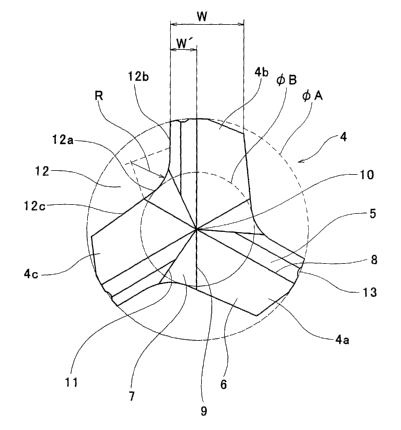
Referring to Figures 2 and 3, the cutting blade tip 4 of the present
embodiment
will be described in greater detail. Three cutting blade portions 4a, 4b, 4c
are
circumferentially equidistantly formed on the cutting blade tip 4, in other
words these
cutting blade portions 4a, 4b, 4c are an angle of 120 degrees apart from each
another, as
shown in Figure 3. The cutting blade portions 4a, 4b, 4c each have a cutting
surface 5
and a flank surface 6. Between each cutting blade portion 4a, 4b, 4c and the
next, a
connection surface 7 is formed between the flank surface 6 and the cutting
surface 5.
CA 02402142 2002-09-05
8
And, in each cutting blade portion 4a, 4b, 4c, a connection line defined
between the
cutting surface 5 and the flank surface 6 forms a main cutting edge 8, and a
connection
line defined between the flank surface 6 and the connection surface 7 forms an
auxiliary
cutting edge 9. Further, the main cutting edges 8 and auxiliary cutting edges
9 of the
cutting blade portions 4a, 4b, 4c cross each other at a blade tip point 10 so
that the
blade tip point 10 is shaped like a peak with no chisel edge.
Further, each of the main cutting edge 8, the auxiliary cutting edge 9, and
the
connection line 11 defined between the connection surface 7 and the cutting
surface 5
which cross each other at the blade tip point 10 extends in a straight line.
In other
words, the auxiliary cutting edge 9 lies on a line extending from the main
cutting edge 8
of a cutting blade portion located opposite across the blade tip point 10.
To sum up, the three main cutting edges 8 and the three auxiliary cutting
edges 9,
these six cutting edges together forming a blade tip of the drill bit, are
alternately
equidistantly formed so that they are an angle of 60 degrees apart from each
other and
extend radially from the blade tip point 10.
Furthermore, concave entrance portions 12 are defined between each cutting
blade
portion 4a, 4b, 4c and the next, continuously extending to their corresponding
chip
ejection grooves 3, respectively. A surface of each concave entrance portion
12 (i.e., a
wall surface of each concave entrance portion 12 when viewed from the bottom)
comprises a single continuous surface made up of a circular arc surface 12a
and flat
surfaces 12b and 12c) continuous with sides of the circular arc surface 12a.
And, the
flat surface 12b is so arranged as to be in parallel with the main cutting
edge 8 on the
side of the cutting surface 5, and a surface of the concave entrance portion
corresponding to the connection surface 7 serves as the circular arc surface
12a. The
CA 02402142 2002-09-05
9
radius of curvature R of the circular arc surface 12a is set as follows. That
is, the radius
of curvature R of the circular arc surface 12a is set in such a way that, on
the side of the
cutting surface 5, an end of the connection line 11 defined between the
connection
surface 7 and the cutting surface 5 crosses the circular arc surface of the
concave
entrance portion at a halfway point of an edge line of the circular arc
surface whereas,
on the side of the flank surface 6, an end of the auxiliary cutting edge 9
crosses an edge
end of the circular arc surface of the concave entrance portion.
Furthermore, other dimension relationships in parts of the blade tip are set
as
follows:
( 1 ) The circumferential thickness W at a cutting blade end of each cutting
blade
portion 4a, 4b, 4c is so set as to be from about 0.2 to about 0.5 times as
great as the
blade tip diameter ~A (see Fig. 3).
(2) The circumferential apparent width W' of the cutting surface 5 of each
cutting
blade portion 4a, 4b, 4c is so set as to be from about 0.2 to about 0.5 times
as great as
the circumferential thickness W at the cutting blade end of each cutting blade
portion
4a, 4b, 4c (see Fig. 3).
(3) The core diameter ~B of the bit body 1 is so set as to be from about 0.3
to
about 0.7 times as great as the blade tip diameter ~A (see Fig. 3).
(4) The tip height H at each cutting blade portion end is so set as to be from
about
0.2 to about 0.5 times as great as the blade tip diameter ~A (see Fig. 2).
Finally, a concave portion 13 for blade tip diameter abrasion confirmation is
provided in an outer peripheral surface of each cutting blade portion 4a, 4b,
4c.
[Industrial Applicability]
CA 02402142 2002-09-05
10
The present invention provides a drill bit most suitable for drilling holes in
materials such as concrete, stone, and so forth.
The present invention is embodied in the above-described manner. However, in a
drill bit of the present invention, the basic configuration of its bit body
such as a shank
is the same as that of this type of drill bit known in the art. Therefore, the
drill bit of the
present invention can be used just by replacement with a conventional drill
bit.
Additionally, in accordance with the drill bit of the present invention, three
cutting blade portions which are circumferentially equidistantly formed around
a cutting
chip. Unlike conventional drill bits for which chisel edges have been deemed
essential
from the structural aspect, the drill bit of the present invention constructed
in the way as
described above has no chisel edge. As a result of such arrangement, when
drilling
holes with a drill bit of the present invention, there occurs no rifling to a
drill hole
during drilling. Further, the present drill bit provides a better rotational
balance,
thereby making it possible to drill holes of high roundness.
Furthermore, since the blade tip point having a peak-like structure always
lies at
the cutting surface center of a drill hole leading end, this facilitates
positioning and, in
addition, makes it possible to drill high-accuracy constant-diameter holes
whose hole
diameter error is held so as not to exceed the allowed value, even when
performing
drilling that accompanies a cutting (impact cutting) operation in which the
blade tip
momentarily surfaces from the cutting surface of the drill hole leading end
and
immediately thereafter starts knocking impactingly.
Further, even when chip lumps are caught between the cutting surface at the
drill
hole leading end and the blade tip during impact cutting, a main cutting edge
and its
adjacent auxiliary cutting edge work together to grind the chip lumps. This
reduces bias
CA 02402142 2002-09-05
11
resistance that the blade tip will receive, and there is no drill bit run-out
during drilling,
thereby improving the accuracy of drilling a hole.
Furthermore, the provision of the concave portion for confirming blade tip
diameter abrasion makes it possible to confirm, at a glance, the advance of
cutting blade
tip abrasion from the degree of abrasion of the concave portion, thereby
enabling an
operator to easily drill constant-diameter holes whose hole diameter error is
held so as
not to exceed the allowed value without having to use a special measuring tool
or the
like.
Accordingly, the present invention provides a drill bit which can be used
suitably
as a drill bit for rotary hammer drills for drilling anchor bolt holes for the
fixing of a
structure in concrete solidified, and the use of such a hole for the planting
of an anchor
bolt provides higher anchor bolt drawing strength in comparison with the case
where an
anchor bolt is planted in an anchor bolt planting hole drilled by a
conventional
technique.
CA 02402142 2002-09-05