Note : Les descriptions sont présentées dans la langue officielle dans laquelle elles ont été soumises.
CA 02402251 2002-09-06
WO 01/67529 PCT/NLO1/00184
BATTERY COMPRISING A PLURALITY OF SERIES-CONNECTED
GALVANIC CELLS
The invention relates to a battery comprising a plurality of series-connected
galvanic cells, a metal casing and at least one layer of electrically
insulating
material between the cells and the casing. Batteries of this type are
generally
known, for example in the form of 9-volt batteries, in which six series-
connected
cells are accommodated. Cells of this type may be stacked inside the battery
or
may be positioned next to one another as upright rod-shaped cells. In general,
in
these batteries the stacked cells are of the zinc-carbon type.
It is customary to provide these batteries in the form of a block of
rectangular
cross section. At one end, a sheet of insulating material then bears two
terminals.
In the case of the stacked battery, the different terminals of successive
cells are in
metallic contact with one another, the top terminal of the top cell being
connected
to the positive terminal of the battery and the bottom terminal of the bottom
cell
being connected, by an electrical connection, to the negative terminal of the
battery. The latter connection is often packaged in a cardboard structure.
The stacked cells can be formed into a unit in various ways. For example,
they may be cast in a resin or may be pushed into a plastic sleeve.
2 0 Since the circumference of each of the stacked cells is under a different
voltage, it is important for the circumference of these cells not to come into
electrical contact with the metal casing. Therefore, for this reason the
stacked cells
are generally packaged in an additional plastic film, which may consist of a
so-called shrink film.
2 5 In case the battery consists of rod-shaped cells which are arranged next
to
one another, these cells are generally arranged with the terminals in
different
directions. As a result, these cells can easily be connected in series, the
first and the
last cell being connected to the terminals of the battery. In this case too,
the casings
of the cells are at a different voltage, with the result that these cells have
to be
3 0 electrically insulated both from one another and also, in particular, from
the metal
casing. For this reason, the assembly of these cells is also surrounded by a
heavy
plastic film, for example in the form of a shrink film.
This shrink film has proven to be an expensive element of the construction,
since incorporation of the special shrink properties requires additional
expensive
3 5 process operations. Fitting of the shrink film is also labour-intensive.
Furthermore,
this film takes up additional space within the battery, which space is to the
detriment of the dimensions of the cells.
According to the invention, the metal casing, on the inner side, comprises an
organic coating layer of the film type which serves as the layer of
electrically
4 0 insulating material. As a result, this organic coating layer is able to
replace the
CA 02402251 2002-09-06
WO 01/67529 PCT/NLO1/00184
-2
plastic shrink film, thus allowing the costs of this shrink film and its
fitting to be
saved. The term coating layer of the film type is understood as meaning
polymer
films which are arranged on the metal by lamination but also polymer films
which
are formed on the metal surface by extrusion. The use of a coating layer of
the film
type has the advantage that this layer, together with the metal casing, is
readily
deformable, for example via deep drawing or wall ironing. Also, it has been
found
according to the invention that an organic coating layer on the metal casing
which
has the same effect as a shrink film can be considerably thinner than the
latter, thus
saving additional space in the battery, which space can be used for the
benefit of
the dimensions of the cells. It should be noted that the metal casing does not
fulfil
any electrical function in the galvanic process within the battery.
According to the invention, the metal casing may also be provided with an
organic coating layer on the outer side, which coating layer is printable or
may
even have been printed on in advance. In this case, unlike the known metal
casing,
this involves the use of a metal plate, for example a steel plate, which has
been
coated on two sides, the coating layer on the inner side of the metal casing
having
the function of providing electrical insulation with respect to the cells, and
the
outer side having the function of being printable and possibly also of
protecting the
metal plate itself.
2 0 The invention also relates to the novel battery, the metal casing
comprising a
wrapper with a longitudinal seam, which wrapper is curled inwards at the ends
of
the battery, the curled edges formed completely enclosing the components of
the
battery to form a cohesive unit. In this case, it is particularly advantageous
if the
organic coating layer on the inner side of the wrapper comprises a
thermoplastic
2 5 which, at the location of the longitudinal seam, has been temporarily
heated so that
the edges of the seam adhere to one another.
The organic coating layer can be applied to the wrapper immediately before
it is fitted during production of the battery. However, it has been found that
it is
preferable to produce the wrapper from a metal plate which has been provided
with
3 0 an organic coating layer.
An alternative construction of the battery according to the present invention
furthermore consists in the metal casing not comprising a wrapper with a
longitudinal seam, but rather comprising a shaped can which is made from a
metal
plate which has been precoated with an organic coating layer. In the context
of the
3 5 present invention, the term shaped can is understood as meaning a can
which is
produced by deep drawing and/or wall ironing. This construction offers the
advantage that the can which is formed can be used as a current-carrying
element.
If the battery is also of the type in which the connected cells are stacked,
the
bottom of the can may be electrically connected to the underside of the bottom
cell,
CA 02402251 2002-09-06
WO 01/67529 PCT/NLO1/00184
-3
and the upper edge of the can is electrically connected to one of the
terminals of
the battery. As a rule this will then be the negative terminal. The connection
between the top side of the cell stack and the positive terminal is then
brought
about in a customary way. By using the sleeve as a current-carrying element,
it is
not necessary to provide a separate electrical connection through the battery
between the base of the bottom cell and the negative terminal of the battery.
Moreover, in this battery design, a separate, loose baseplate is rendered
superfluous. Both measures lead to simplification of the assembly process of
the
battery, resulting in a clear cost saving.
The invention will now be explained with reference to a number of figures.
Fig. 1 diagrammatically depicts a 9-volt battery of a known type.
Fig. 2 shows an improvement to this battery according to the invention.
Fig. 3 shows another embodiment of the improvement according to the
invention.
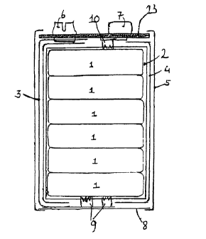
Fig. 1 diagrammatically depicts a 9-volt battery of the zinc-carbon type. Six
stacked galvanic cells which are connected in series are denoted by reference
numerals 1. Each of these cells has a voltage of 1.5 volts. The six cells are
cast
together in a synthetic resin to form a block 2. The block 2 is surrounded by
a
heavy shrink film 4 which electrically insulates the cells 1 from a metal
casing 5.
2 0 The metal casing 5 consists of a wrapper which is closed by means of a
longitudinal seam (not shown). At the top and bottom ends of the battery, the
metal
casing is curled inwards, with the result that a baseplate 8 and a top plate
13 are
enclosed. A positive terminal 7 and a negative terminal 6 are secured in the
top
plate 13. In this case, the positive terminal 7 is connected to the positive
terminal
2 5 of the top cell 1 by means of a sharply serrated element 10 which punches
plastic
layer 2. In a corresponding way, one or more sharply serrated elements 9,
which
are in electrical contact with the negative terminal of the bottom galvanic
cell 1,
are situated on the baseplate 8. These elements 9 are connected to the
negative
terminal 6 by means of a cardboard-packaged metal strip 3.
3 0 The plastic shrink film is of a type which is known per se. A plastic
shrink
film of this type is relatively expensive and fitting it around the block 2 is
labour-intensive. Moreover, this plastic shrink film takes up additional space
inside
the battery.
In the embodiment according to the invention as shown in Fig. 2, these
3 5 drawbacks are avoided. The metal casing S, which in this case too is a
wrapper, is
produced from a metal plate which on the inner side of the wrapper which is to
be
formed is provided with an organic coating layer 11 in film form. This layer
takes
over the function of the plastic shrink film, with the result that this shrink
film can
be omitted. The additional space inside the wrapper which is made available as
a
CA 02402251 2002-09-06
WO 01/67529 PCT/NLO1/00184
-4
result can be utilized by making the cells 1 of slightly larger design, thus
also
increasing the capacity of the battery. It should be noted that in Fig. 2 many
of the
reference numerals refer to elements corresponding to those shown in Fig. 1.
It will be clear that the metal plate with the coating layer 11 on the inner
side
of the wrapper formed may also previously have been provided with an organic
coating layer on the outer side of the wrapper. A coating layer of this type
is not
shown in Fig. 2. A layer of this type is preferably selected from the type
which is
printable. If appropriate, this layer may already have been printed on before
a
wrapper is formed from it.
1 o Fig. 3 shows an embodiment of the novel battery in which the metal casing
comprises a shaped steel can which is made from a steel plate which has been
precoated with an organic coating layer. In this case, can 5 bears an organic
coating
layer, which consists of electrically insulating material, on the inner side.
If
desired, in this case too the outer side of the can 5 may once again be coated
with a
pre-printed or printable plastic layer.
In this embodiment, the bottom of the can 5 replaces the baseplate 8. The
serrated elements 9 are attached directly to the base of the metal can, while
the
negative terminal 6 is also in electrical contact with the wall of can 5 by
means of a
soldered joint 12. As a result, the can wall has become a current-conducting
2 0 element between the negative terminal of the bottom cell 1 and the
negative
terminal of the entire battery. As a result, the cardboard-packaged metal
strip 3
from Figs. 1 and 2 has been made superfluous.
It will be clear that the novel constructions according to the present
invention
can also be applied to batteries in which series-connected galvanic cells are
not
2 5 stacked but rather comprise rod cells arranged next to one another.