Note : Les descriptions sont présentées dans la langue officielle dans laquelle elles ont été soumises.
15-05-2001 ui ic. w n~ DG7c~J~ n-1 I G111WIy I L~C '~ ~,~~ NO 000000104
AePARATOS FOR PROPOLSION IH OHhONG CAVITIES AND PIPES.
The present invention concerns an apparatus for propulsion
in oblong cavities and pipes; as stated in the preamble of
the follv~ring claim 1
Hy oblong cavities is meant pipes, ducts, drilled or mined
holes in rock, or wells which are drilled with or without
casing in the ground (oil related holes), in metals or
so ether materials.
According to the invention the apparatus is used when
inspection yr different kind of work are performed in such
cavities. According to the invention the apparatus may be
~5 used to force forward the equipment for boring the hole,
but can also be used for pulling equipment through the
cavity.
In such cavities, pipes and ducts, where it is not possible
2o to use people there is often need for inspection, service,
maintenance and other work to be done. It might also be
necessary to increase the propelling power on the drilling
equipment which is drilling hQles/wells.
25 In vertical holes. for example in oil related wells, it is
normal to pull the necessary equipment down into the well
by means of gravity, if it is not pushed downward by means
of a pipe. In horizontal holes or pipes where it is not
possible to utilise gravity, an apparatus for pulling or
AMENDED SHEET
CA 02402923 2002-09-13 ~AAFN~'iF~l ~N~~T
15-05-2001 CA 02402923 2002-09-13 NO ~~~~~~1~~
2
pushing is required for the equipzaent to be transported.
Different hydraulic methods to pump forward equipment have
also been tested. The methods which are based on pipes for
transporting the equipment, require a lot of space and
s personal to run it all day and night, and further the
transportation speed is relatively low.
Fro~a British patent GB-1.328.886 a vehicle coupled to a
coiled tubing is known, thus enabling the vehicle to pull
~o yr push the coiled tubing.
from British patent patent GH-2.196.715 a device which is
driven forward by liquid or gas pressure through a pipeline
is known.
From GB-2.200.970 a vehicle having motor powered wheels is
known, but where propulsion may be provided also by means
of chain and sprocket wheels.
2o From U.S.patent 4.941.511 a joint separated vehicle is
known, where one part includes the energy source and the
other part includes a motor connected to the driving
wheels. A similar device is known from GB patent
specification 2.122.713.
From EP patent specification 0.461.964 a vehicle where
propulsion is generated by means of motor driven belts or
wheels is known.
3o In DE patent specification 3.206.033 there is shown a
vehicle where the propulsion is provided by means of an
obliqued wheel, the wheel axis of which is mounted
eccentric on an shaft shich is positioned centric of the
vehicle. The wheel is therefore aligned mainly crosswise to
the traction direction. Said eccentricity causes the wheel
to be in contact with the pipe wall and the contact point
moves as the shaft is rotated. The oblique position of the
wheel causes that the movement of the contact point also
AMENDED SHEET
onn~Nn~n cu~~T
15-05-2001 '-" ~ ~ ! ' CA 02402923 2002-09-13~v~~~
generates propulsion. Further the vehicle is also equipped
with radial directed wheels which abut the pipe wall for
centring the vehicle inside the pipe line. Further the
vehicle is equipped with radial directed wheels which abut
s the pipe wall for centering the vehicle inside the pipe,
and for giving counter-torque to the drive motor.
from S0 patent 481 784 a v~hicle is known where several.
crosswise spring loaded wheels are mounted adjacent the
1a surface of the vehicle so that the wheels abut the pipe
wall and centers the vehicle within the pipe line. When the
vehicle rotates around it's own axis, the wheels cause a
propulsion corresponding to the wheel angle, This apparatus
need counter force torque.
7.5
From Norwegian Patent No. T78.27fi a pipe tractor arranged
to move within canals and pipes is known, in that the end
portions of the tractor is mounted and equipped with spring
loaded arms to which crosswise wheels are mounted, and the
zo wheels abut the inner surface of the pipe, so that side
force affecting the wheels provides for propulsion of the
vehicle when the end portions are rotating. The end
portions rotate in opposite directions related to each
other, and one of the ends acts as counter torque for the
25 other end, and visa versa.
From International patent PCT/GH93/0111 a down hole tool is
known, for providing rotary support of a downhole assembly
in which the tool is incorporated. The tool also converts
30 rotary contact with the wellbore into a longitudinal force
which turns the assembly along the wellbore. The tool
comprises a stabiliser including rollers, wherein the
taller axis are skewed to be tangential to a notional
helix, such that the natural path of xoller contact with
3s the wellbore has a longitudinal counponent in addition to
the usual circumferential path. The tool can be used on
drill strings and in downhole assemblies with motor, The
AMENDED SHEET
AMFNI~Fi~ ~NFFT
15-05-2001 CA 02402923 2002-09-13 NO 000000104
tool may also pull a cable supplying the tool with
' electricity/hydraulic power for the propulsion machinery.
The pulling-/pushing apparatus of today are ~ancumbered with
a lot of disadvantages. Firstly they are very complex, they
have a limited operation range and they are produced for
dedicated actionsJtasks which they are intended to execute.
There are also strict requirements regarding the
surroundings in which they axe used.
io
It is an object of the invention to prepare a new and
improvzd propulsion apparatus for transporting
(pushing/pullinq) through pipes/cavities.
further it is an object to produce an apparatus which msy
effect an increased pulling power, independent of the
design of the cavity, and reduced demands to the
strengthltoughnass of the inside wall of the pipe/cavity.
2a A further object is to produce an apparatus that can work
without any Gaunter torque. Finally it ~,s an object to
produce a shorter propulsion apparatus with lower Weight,
therefore being easier to handle, and may carry more
equipment for each trip.
The apparatus of the present invention is characterized by
the features which are d~fined in the characterizing clause
of the following claim 1.
3d The preferred embodiments of the apparatus in accordance to
the inventive are stated in dependent patent claims.
~lith this invention an apparatus with a simple construction
is designed, and which is easy to run and covers a large
working area, and more specific the apparatus may operate
in ducts having vary variable cross section and variable
diameter, that is to say within the working range of the
apparatus Within the rna.ximum and minimum diameters far its
AMENDED SHEET
nnn~NnFn ~N~FT
15-05-2001 .~ ~ CA 02402923~ 2002-09- 3 Ky'~~
operation. The apparatus involves a simple design so that
different sizes of it may pull/push i holes having diameter
ranges of millimetre to several meters.
s The apparatus is further designed for automatic adjustment
of the pulling force, independent of the design of the
cavity. This occur when the traction roller (the sliding
element), against the action of spring force, changes its
orientation from its maximum angle position relative to the
1o longitudinal axis of the appa~catus, and to the position
where it is perpendicular to the longitudinal auis. Then
the apparatus rotates With the wheel' running so the
propulsion of the apparatus becem~s zero. Thus if the mass
of the tool to b~ pulled and/or be pushed becomes too
is large, one avoids the apparatus being exposed to overload.
The contact point of the traction roller towards the pipe
wall moves in a non-slipping revolving movement around the
pipe wall.
2a It has no consequences either the cavity is angular or
round, and the diameter may be changed continuously as long
as it stays within the maximum/minimum operation diameter
of the apparatus. In contrary to the previously known
traction mechanisms, which require uniform holes, this
25 apparatus can go into any kind of holes.
The device according to the invention, dues no need any
counter tongue, due to the fact that its motor rotational
torque has internally counter force within the device.
The apparatus may generate high push-/pull forces, it can
operate in varying diameters, cope with varying hole
geometries, it can automatically vary speed and pull-/push
force with regard to the load, and is gentle to the inside
wall of the cavity.
The apparatus has a simple construction since it consists
of a number roller elements each having similar design.
AMENDED SHEET
4MFNI~F1~ SNFFT
15-05-2001 " " -- ~ ' ' "' - ".' "" ""' ' ""'"°""'''''°~ NO
000000104
6
they may be single standing or involve several mounted one
after another.
The individual elements may be mutually displaced relative
s to each ether, and perpendicular to the travel
direction/longitudinal axis of the apparatus. The roller
elements mounted in one assembly will rotate at the same
speed.
1o The apparatus according to the present invention will now
be described more detailed in the following, with reference
to the accompanying schematic drawing, and wherein:-
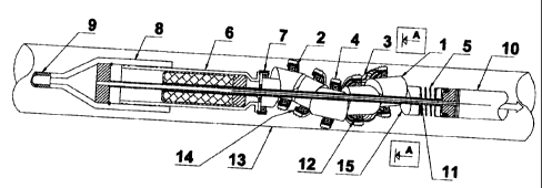
Figure 1 shows a ce~aplete propulsion apparatus able to move
15 inside a cavity/pipe. The rotational direction of the
roller elements is also shown.
Figure 2 shows in three different sections an example of
the construction of a xoller element, and where the
inclined surfaces of roller element is shown, and a sliding
element (a bearing, such as a ball bearing) where the outer
part may rotate around the peripheral surface of the roller
element.
25 A plurality of roller elements mounted one after another is
shown on Figure 3. The roller elements are drawn in section
inside a pipe shaped cavity. The arrows show the
compression of the roller elements which makes them forced
outwardly towards the inner wall of the cavity,
Figure 9 shows the same as figure 3, but includes in
addition the central shaft extending through the assembly.
The figure also shows the internal oblong radial extending
slotf the extensive of which defines defines how far a
3s rolling element can be radially displaced with resepct to
the shaft.
AMENDED SHEET
CA 02402923 2002-09-13 AMFNI~Ff~ SNFFT
15-05-2001 CA 02402923 2002-09-13
7
On figure 5 is the roller elements seen from i front when
the apparatus includes five or more roller elements mounted
une after another. The roller elements are mounted have a
mutually displacement of 72° (degrees).
The movement of the apparatus as seen from the side on
moving forward is shown on Figure 6.
Figure 7 shows the anchoring of the roller element
including a spring ccastruction.
Figure 8 shows an exampl~ in practical use for the
apparatus of the invention
Introductory the reference is to the figures 1'2. Figure 1
shows a complete apparatus for propulsion in a cavity 13,
for instance inside a formation of rock ground.
The apparatus includes a plurality of roller elements 1
2o which are arranged on line against each other. Each roller
element 1 has initially a cylindrical shape where each
plane end Surface are cut off to establish inclined sliding
surfaces 15 with respect to the plane radial surface, as
clearly shown on figure 2. In the sliding direction the
Zs surfaces ef two adjacent surfaces comprises mutually
corresponding tongue and groo~re like guiding means for
defining the sliding direction of the roller elements
as they are coiapressed axially and thus slide radial away
from each other, defined by the angle between the surfaces
30 (see below).
The two facing inclined plane surfaces of two adjac~nt
roller elements, which are positioned against each other,
must nave the same angle to the longitudinal axis 7c through
~5 the element. This angle is in the range of 0-9D'.
I
When the elem~nts 1 are arranged against each other and
having the inclined suzfaces mutually towards each other in
AMENDED SHEET
nnncNncn cucc-r
15-05-2001 CA 02402923 2002-09-13 NO 000000104
8
axial direction, and when this assembly is exposed to axial
compression the elements 1 will slide in radial direction.
The mutually inclined surfaces 15 on two neighbouring
elements 1 then will slide a~,ong each other in a way so
s that they slid~ in radial outward directive.
In accordance to a preferred embodiment, the sliding
surfaces of two adjacent roller elements may have a shape
so that the elements mutually displaces 1~v° in Opp.~.:itC
1o directions. Then the central shaft will not be exposed to
strain_ But however, dtly ir~ternsl an5la au ;r b~ chaser..
As shown in figure 2, each roller element includes a slot
30 extending through tha whole element in axial direction.
The slot extends in radial direction from the central shaft
32 and a distance towards the outer well 33 of the elezaent.
Alternatively the slot rnay be completely open and penetrate
the wall 33. The slot 3Z is of such dimension that the
elament may be treaded onto the central through extending
2o shaft 11, and it can be displaced in radial direction
outwards and inwards on the shaft limited of the Outer
extensions of the slat. The central shaft 12 extends
through all elements 1.
25 when the roller elements are axially compressed, the
inclined cut sliding surfaces 15 cause the roller elements
to press towards the wall of the cavity in which they are
operating. When the apparatus ccdrives~ forward in a cavity,
the roller elements 1 at the back will push on the roller
3o elements further forward in the assembly, thus causing also
they being pressed outwardly towards the inner wall 13 of
the cavity. This pressing force increases with the power of
which the propulsion apparatus must add to the equipment it
movesitransfers. As indicated in figure 1 the set of
35 propulsion segments mounted between the motor section 6 and
an equipment section 5 (including an equipment section 10)
on the other end of the shaft. These sections 6 and 5/10
l
l
AMENDED SHEET
r4MFN~1F17 ~1-IFFT
15-05-2001 CA 02402923 2002-09-13 NO 000000104
9
are used for generating the necessary axial compression of
the roller elements so they are pressed radial outward.
With reference to figure 2, each roller ~lements I is
s surrounded by a ring shaped circular sliding element 4
which slides relative to the roller element 1. A ball
bearing 2 comprises a stator part 40 which is mounted
recessed in a seat in the circular outer surface of the
roller element, Thus the sliding element 4 represents a
zo circular shaped rotor part rotating on the outside of the
stator 90 via said ball bearing 2.
The sliding element 4 is mounted in such way that it forms
an angle to the longitudinal axis X through the roller
i5 elemrent, This angle defines the climbing angle (the pitch)
of the apparatus during the propulsion, i.e. it decide how
fast the apparatus screw itself through the cavity.
All roller elements are produced in a manner so that the
2o stator- and rotor part of the sliding element defines the
same Inot perpendicular) angle with respect to said central
axis X.
In the preferred embodiment where two produced roller
25 elements are mounted facing each other having their slots
extending respective 180° in opposite direction, the two
sliding elements, viewing the apparatus from one aide, face
mutually in opposite direction. Since the elements are
displaced radially 180° in opposite direction, the
3o diametrical opposite points of the respective rotor parts 9
will establish abutment against the inner wall of the
cavity.
When the apparatus, consisting of a number of identical
35 roller elements, are forced together in axial direction,
the roller elements will be forced radial outwards in given
directions until an paint on the bearing-rotor parts form
contact towards the cavity inner wall.
AMENDED SHEET
AMENDED SHEET
15-05-2001 CA 02402923 2002-09-13 N~ ~~~~D1~'
1
An assembly of roller elements including a given angle
between the sliding surfaces is shown on figure 1. The
sliding surfaces are designed in such a way that the two
first roller elements, seen from the left, are pushed
substantially one way (upwards on the figurey~ while the
two next roller elements move in the opposite direction
(downwards the figure), Thus the apparatus is centred, that
is to say it covers the complete circumference, 72° x 5 =
1o 360°. To gain such a balance the sum of the mutual
displacements between the elements must be 360°. Thus a
roller element is turned/displaced a given number of
degrees around the shaft 11 with respect to its facing
neighbouring roller element, so that the sum of the angle
~5 offsets for all elements in the raw is said 360°.
When five roller elentants are mounted in the row, there is
an offset angle of 72° between each roller elements so that
the sum of the angle offsets is 360°.
Figure 1 also shows a motor 6 which by means of a
transmission 7 transfers rotational force to the roller
elements 1 and rotational counter tvrgue to the outer part
of the sliding element Q. The rotational force acts between
stator 40 and rotor part of the sliding element 9. The fact
that the rotational force operates between the inner and
outer part of the sliding element, effects that the
rotational torque between the stator and rotor of the motor
equalises in the sliding element, and thus the motor has
3o counter torque. If the motor is reversed, the apparatus
will move in the opposite direction. The rollet elements
will normally be ratativnal fixed to each other
simultaneously as they have a degree of freedom fro~a the
centre of assembly and outwards to periphery, thus it is
3s sufficient, for effecting the complete assembly of roller
elements to rotate, to supply motor force to the roller
element being closest to the motor 6 and transmission '7.
When the motor is running the apparatus shown in figure 1,
AMENDED SHEET
AMENDED SHEET
15-05-2001 CA 02402923 2002-09-13 N~ ~~4~~01~
11
exhibits a buckling forward movement, and it buckles in all
sections simultaneously. The outer part of the sliding
segment establishes point by point contact with the inner
wall of the cavity and effects an axial directed force so
that the apparatus moves Forward in desired direction,
When propulsing in a cavity 13 where the diameters are
within the minimum and maximum diameters of the propulsion
apparatus, all propulsion segments 1 with wear shoes 4a on
1o the outher part of the circular sliding elements or the
like, are always contacting the cavity wall. Ti the
~rssembly includes a separate motor 6 and transmission 7 as
shown on the figure, it will it move forward without being
rotntionally coupled to the central shaft 11. It will then
have pulling force at the resx end 8 and pushing force in
the front end 10 at the same time as the roller elezaents 1
are forced outwards. The design of the propulsion apparatus
establish an outside helical shaped channel on the outside
of the apparatus, wherein fluid such as liquid can flow
2o through. Fluid can also flow through the central shaft.
As noted it is the mounting of sliding elements an the
roller elem~nts that makes the propulsion apparatus move
forward when the roller elements rotate about their own
2s axis. The sliding segments are mounted in such way that
they it have an inclined angle on that side of the roller
element which is forced towards the wall of the cavity I3.
The inclined angle of the sliding element 4 represents the
angle by which the rotor part (with external wear shoe) of
3o the sliding eleiadnt is rolling again3t the inner wall of
the cavity.
According to a preferred embodiment the design of the
sliding element may comprise a spring mechanism which is
35 able to displace the sliding element so that the elements
angle changes from a maximum angle to a position being
perpendicular to the axis. This mechanism is shown in the
figures 7A-C.
AMENDED SHEET
AMENDED SHEET
15-05-2001 CA 02402923 2002-09-13 NO 000000104
12
- Figure ? shows the rotor elemnt 4 mounted in its seat
surrounding the the roller element 1. In its inclined
position the rotor element 4 is clamp~d by means of a
spring construction 50 made of a number of circular and/or
wave shaped leaf springs (or for example a coil spring)
which is also surrounding the roller element. When the load
to be pulledlpushed by the apparatus gradually increases,
as indicated with arrows P on the figures 7, also the
1o apull~ of the attaching point or surface of rotor part
towards the inner wall of the cavity increase. The rotor
part will then pivot towards its zero position, where the
apparatus rotates only without any propulsion. Just before
the apparatus comes to a stand-still the apparatus effects
its greatest pulling capability but exhibits its smallest
climbing angle/velocity. It can be said that the apparatus
continuously changes transmission downward from its maximum
climbing angle to its minimum (zero) climbing angle.
2a Thus the tractive power increases when the spring is
crnapressed so that the previous mentioned climbing angle
reduces, the propulsion apparatus will slow down speed and
the tractive power increases, If the tractive power is
large enough the mentioned angle will be reduced towards
zero degrees climbing angle ti.e, perpendicular to the
axis), and the propulsion apparatus will be at stand still
and push with a constant power. A climbing angle of zero
degrees for the rotor part of the sliding element occurs
when it is perpendicular to the central shaft 11, and it
3o will look like the rotor part 4 of the sliding element
rotates (non slipping) around a shaft without any climbing
angle_ A possible outer skin or membrane (figure 1) can
preferably be fixed~i.e. in a slot between the inner and
outer part (wear shoe Aa) of the sliding elements. Then'
only the outer wear part will be visible front outside.
Figure 3 shows a plurality of roller elements 1 mounted one
after another in an oblong cavity 13. The figure shows how
AMENDED SHEET
AMENDED SHEET
15-05-2001 ' NO 000000104
13
the roller elements 1 presses each other axially and how
this pushes all the roller elements 1 outward towards the
inner wall of the cavity 13.
Fig.9 shows mainly the same as fig.3, but this figure shoes
the central shaft 11. The figure shows that the central
shaft is rotationally dis-coupled from the roller elements
1. The figure also-shows the restrictions with regards to
the maximum and minimum diameter when a straight shaft i~
Zo conducted through the propulsion apparatus. The roller
element 1 can move as far from the centre position around
the central shaft 11 as the oblong hole in the roller
element 1 permits.
1~ The propulsion apparatus can also be produced without any
straight central shaft 11, and then the maxa.mumlminimt~m
diameter of propulsion apparatus may have another ratio.
Ftgura 5 shows a front view of the propulsion apparatus
20 (section A-A on~figure 1).
The figure shows that all the roller elesaents 1 are in
contact simultaneously and that a helical shaped channel
establishes on the outside of the propulsion apparatus in
25 such way that fluid nay pass by outside of the propulsion
apparatus.
Figure 6 shows the movement of the propulsion apparatus as
seen from the side when movinglwinding forward.
The figure shows a solution where roller elements are
mutually connected with a metobrane 3, such as rubber, or a
metal membrane having a so-called accordion shape. The
membrane may be threaded over the complete construction and'
is attached to the rotor element at each of the roller
elements and to the outer shield of tha motor. Then the
motor will rotate the roller elements and said outex parts
will move in the mentioned winding forward movement.
AMENDED SHEET
CA 02402923 2002-09-13 AMFNI~FI'1 ~NFFT
15-05-2001 CA 02402923 2002-09-13 NO 000000104
14
' Tf roller elements of the apparatus is not engaged towards
the inner wall of a cavity, then without said membrane the
apparatus will lie.still. Hut with a membrane, as
s mentioned, the apparatus ,sill wind in a forward direction
even if it is lying on a plane surface, because the roller
elements are rotationally mutually connected.
The uppern~ost figure shows a cut through section without
1o roller elements, The arrows show the direction of movement
of the different elements in the assembly. The big arrow
shows the forward travelling direction to the apparatus.
The figure at the bottom shows the same as the uppermost
15 figure, but hare the propulsion apparatus is Seen from the
outside. The wear shoe 4a of the sliding elements 4 and the
membrane 3 is shown. When the membrane 3 is used in this
assembly the outer parts of the sliding elements 4 are
mutually rvtatably connected.
Hy the way, if the sliding element has its own motor drive
the inner driving unit will rotate and push the conical
parts so that point of contact of the outer ring against
the wall of the cavity moves forward in a helical shape.
The membrane will also protect the sliding elements 4 from
influence of dirt and particles as well as the sliding
elements can he surrounded by oil for lubrication and for
cooling.
~o
Fiqure B shows a possible way of using this propulsion
apparatus when drilling holes in rock formations to for
instance a water reservoir. This propulsion apparatus can
be produced in all sizes, and used for operation in all
~5 oblong cavitues where tasks that require propulsion are to
be effected.
j AMENDED SHEET
nnn~Nn~n cNC~-r
15-05-2001 CA 02402923 2002-09-13 NO 000000104
The invention shall not be restricted by the exataples of
' its embodiment specified above, in that many variations are
possible within the range of the idea of the invention as
defined in the claims.
AMENDED SHEET
AMENDED SHEET