Note : Les descriptions sont présentées dans la langue officielle dans laquelle elles ont été soumises.
CA 02403952 2008-07-29
Method for the Uphill Casting of Cast Pieces in Sand Dies with Controlled
Solidification
This invention relates to a method for uphill casting in sand molds with high-
resin casting cores,
or in particular casting cores containing binders, and with directed
solidification of metal
castings with at least one cavity, particuiarly of pmtotypes of engine blocks
or cylindtr heads,
for eaample for internal combustion engines that are provided with a cavity
for the passage of
coolant water.
Corresponding castings in the form of engine blocks or cylinder heads with
channels for ooolant
fluid are made today in large numbers of light metal or aluminum or magnesium
alloys. Such
castings pursuant to the state of the art are made by casting liquid metal in
chill molds, which
produces good dimensionally stable surfaces. A general problem for casting
production rrsults
from the necessary coolant water channels, which can be produced practically
only by using
casting cores. These casting cores are so-called lost cores, which have to be
removed after the
cooling of the block. They are usually made of mold compounds, for example of
mold sand
using binders. Another method for producing such blocks consists of making
patterns out of
polystyrene foam. During the casting of the liquid metal, the polystyrene foam
melts and bum
up. In both cases the gases formed have to be removed by suction. Furthernwre,
gas bubbles may
form during the casting, which lead to gas defects and leaks in the finished
casting.
According to DE 3618 059 A 1, the gases formed in the chill niold during
uphill casting are
drawn offthrough two ventilation ports during the filling, wbich are placed at
the highest point
of the casting mold. In this case the ventilation ports have to be so tight
that the liquid metsl
cannot pass through. For the tight infeed of the casting, the casting pressure
as a rule has to be
maintained up to a given degree of solidification so that the shrinkage of the
casting occurs in the
area of the riser tube in the poured section of the mold.
This method c,annot be carried over to the production of prototypes by means
of sand molds. In
the preparation of prototypes, high-resin laser-sintered casting cores that
have high binder
content are being used more and more frequently. These likewise cause gases
during the casting
that can bring about foam, pores, and bubbles on the surface of the casting.
Because of later mass
]
CA 02403952 2002-09-24
Transtek Document No. GE0725
production in the automobile industry, high-performance prototypes also have
to be made
available, which guarantee a high quality standard, especially for high-load
components.
For this reason, the invention has the objective of developing a casting
method, especially for
prototypes, that provides castings with assembly line characteristics.
It is well known that casting cores are given ventilation holes at the core
marks in order to carry
off the casting gases from the casting core during casting. According to DE 24
26 717 A 1, it is
known that the air in the mold cavity is carried off by suction during the
casting, and a partial
vacuum is produced in the mold cavity. The air in the mold cavity can thus
cause no
counterpressure with the gases that are formed, so that the actual casting
pressure is reduced, at
least in the area of the outer wall of the later cast part. This can avoid gas
defects, because the air
can escape quickly and at the right time. The elevation of casting pressure
depends on a
corresponding increase of the specific pressure of the surrounding atmosphere
acting through the
mouth of the mold or the head of the casting. To produce a casting, a mold is
used in which the
perforated wall of the mold cavity is connected to the vacuum source through a
pipe. The rate of
filling with molten metal can thereby be increased. The same conditions thus
exist in the method
described in DE 22 58 461 Al and DE 32 40 808, in which the casting molds are
provided with
air-permeable walls and are connected to a vacuum source.
However, increasing the rate of filling may cause turbulence in the molten
metal, by which parts
of the sand mold and slag are loosened and enclosed. To prevent this as much
as possible, uphill
casting has proved useful for mold casting, since the molten metal in this
case is not made
turbulent, but the mold is filled with a calm front of melt. Oxide inclusions
in the casting can
thereby largely be avoided.
The task of the invention thus consists of a method for uphill casting in
which a low-turbulence
flow of liquid molten metal is provided for while removing air from the
casting mold. Hindrance
to filling from pockets of air in the mold is also to be eliminated. At the
same time, dense and
pore-free mechanically strong castings are to be produced by the method.
2
CA 02403952 2002-09-24
1'IaIiSL@K UOCuT[ler1L N0. li6V /65
The task is accomplished according to the invention by a method for uphill
casting in sand molds
in which the cavity formed by the high-resin or binder-containing casting core
is subjected after
loading the molten metal to reduced pressure, which eliminates the pressure of
the core gases
relative to the molten metal, with the entry of core gas into the molten metal
being prevented.
Pursuant to a preferred refinement of the invention, the reduced pressure in
the cavity is
generated by a vacuum device connected to at least one core mark. While the
molten metal in
known gravity casting flows into the casting mold under the influence of
gravity and solidifies
under normal atmospheric pressure, in the proposed method the molten metal
solidifies under
reduced pressure that is generated in the core.
According to another refinement of the invention, the removal of air from the
casting mold is
accomplished through the vacuum device connected to the core marks. Removing
air from the
casting mold through the core marks has the advantage that no reduced pressure
can be created in
the casting mold during casting that increases the rate of filling by molten
metal. This can be
attributed to the fact that the reduced pressure in the cavity can be created
only when the casting
core is completely enveloped by liquid molten metal and is enclosed air-tight
by it. Thus air can
be removed from the casting mold during the casting.
According to a further development of the invention, dense infeed can be
improved if the casting
mold is cooled during the venting of air. Cooling causes directed
solidification of the molten
metal, which will be explained in detail below with reference to an example of
embodiment and
with reference to drawings.
The drawings of the example of embodiment show:
Figure 1 cross section through a casting mold with a base core,
Figure 2 the base core of Figure 1 with a water-jacket core, and
Figure 3 a perspective illustration of a base core in schematic
representation.
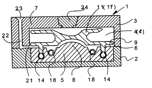
The casting mold 1 according to Figure 1 for implementing the method pursuant
to the invention
has a horizontal parting line 6 between a bottom box mold 2 and a top box mold
3 made of mold
material 7, which forms a mold cavity 4 for a casting, especially for a
cylinder head 4', that is to
3
CA 02403952 2002-09-24
Transtex llocument NO. Ci6U /65
be filled with the liquid molten metal to be cast. Mold sand with a resin-
containing binder is
preferably used as mold material 7 in the example of embodiment. However, the
invention is not
limited to the illustration of the casting mold 1 made of mold sand. The
bottom box mold 2 has a
base core 5, for example with a bulged subsection 8 that undertakes the
modeling of the cylinder
head 4' on the combustion chamber side. It is preferred to use for the base
core 5 a mold material
7 that can be machined by milling. The parting plane 6 between the two halves
of the mold runs
horizontally in the plane of the seal face 9 of the future cylinder head 4'.
The bottom box mold 2
including the base core 5 can also be made as one part by conventional mold
methods.
The mold cavity 4 for the cylinder head 4' also has a core with appropriate
core marks 12, which
is called the water-jacket core 11 below in the example of embodiment. The
core marks 12 are
anchored in the base core 5. The water-jacket core 11 forming a cavity 11' is
assembled as one
piece or consisting of several core packets into a water-jacket core 11. The
water-jacket core 11
is produced in the production of prototypes with a high-resin mold material by
selective laser
sintering. Water-jacket cores 11 made by laser sintering ordinarily have a
binder fraction that is
multiple times higher, so that elevated evolution of casting gases is found
during the casting.
There are ventilation tubes 14 imbedded in the base core 5 below the core
marks 12 that are
provided with a ventilation hole 15 in the area of the core marks 12 according
to Figure 2, so that
the core marks 12 are connected on their faces with the ventilation holes 15.
A system of
ventilation holes can be continued in the core or set into the core itself.
Alternatively, the cores
can also be anchored in the top box mold 3 or in other mold elements.
As shown in Figure 3, the ventilation tubes 14 can be provided with multiple
ventilation holes 15
so that each core mark 12 is deaerated. The ventilation tubes 14 are connected
outside of the
casting mold 1 to a vacuum device 16, not shown.
As also shown in Figure 3, cooling channels 17 are provided in the plate-like
base core 5 that are
used to hold a cooling system, for example in the form of cooling tubes 18.
The cooling channels
17 are open on the casting chamber side so that the inflowing molten metal is
cast directly on the
cooling tubes 18 on the cylinder head 4'. The cooling system with cooling
tubes 18 can be
provided with a black wash prior to casting to prevent bonding to the casting
metal. The adhering
4
CA 02403952 2002-09-24
Transtek Document No. GE0725
cooling system under some circumstances can even be removed manually after
solidification.
Between the cooling system 18 and the later seal surface 9 of the cylinder
head 4' there is a
machining oversize 19 so that the cooling system 18 and its imprint can easily
be removed by
cutting tools after casting.
The casting mold I according to Figure 1 is filled in the example of
embodiment from the side
through a horizontal slot 21 that is provided with an infeed funnel 23 through
a casting system
22. The infeed funnel 23 is at the same height as a feeder head 24 located
above the casting mold
1 that is intended for dense feed. In this was the casting mold I is filled at
the lowest point as
with a chill mold with a riser pipe. An undesirable temperature distribution
is created since the
infeed funnel 23 does not form the feeder head 24 with the last molten metal
fed in. The
temperature distribution is inverted by using the cooling system at the bottom
of the cylinder
head 4'. The principle of directed solidification is thereby realized, since
the temperature rises
toward the feeder head 24. This can be assisted by interrupting the filling of
the mold when the
bottom level of the feeder head 24 is reached and casting the rest of the hot
metal directly into
the feeder head 24.
This invention presupposes that a particularly stress-resistant structure is
developed by directed
solidification, that in the case of a cylinder head 4' is located on the
combustion chamber side
with the overlying water jacket. This area is most highly stressed in
operation by the prevailing
temperature gradient. During the casting, the metal cast last, which is the
hottest at this point, is
in this area. Consequently the development of bubbles is prevented by the
targeted cooling.
Bubbles result from the contraction that originates during the casting of the
molten metal and
during the subsequent solidification of the metal. The invention also proceeds
from the
consideration of removing the gases formed during the casting at the core
marks 12 by suction,
and producing reduced pressure in the cavity 11' after casting. The reduced
pressure here is
achieved automatically when the casting mold I is completely filled with
molten metal.
As long as the casting mold I is not completely filled or the cavity 11' is
not enclosed by molten
metal, only an insignificant pressure increase can occur without increasing
the rate of filling of
the casting mold 1. In uphill casting, the casting mold I is therefore filled
with a calm molten
front. After the filling process is complete, resistance at the ventilation
tubes 14 is increased and
CA 02403952 2002-09-24
Transtex Document No. GEU'/l5
reduced pressure that is greater than the metallostatic pressure in the molten
metal can be created
in the cavity 11'.
In this way, dense infeed of the area of the cylinder head 4' on the
combustion chamber side is
provided for by the reduced pressure in combination with the directed
solidification by cooling.
The area that solidifies quickly is after-fed by the rest of the molten metal
from the feeder head
24. Prototypes of production line quality can be made in this economical way
by sand casting.
The invention has the effect that castings of outstanding casting quality are
formed. Largely
pore-free and mechanically very strong castings are produced. Besides an
especially high-grade
casting grain structure, the development of bubbles is effectively avoided.
6