Note : Les descriptions sont présentées dans la langue officielle dans laquelle elles ont été soumises.
CA 02404575 2002-09-23
1
TITLE OF THE INVENTION:
Method Of Joining Coiled Sucker Rod In The Field
FIELD OF THE INVENTION
The present invention relates to welding with
hydrocarbon gas.
BACKGROUND OF THE INVENTION
Continuous coiled sucker rod has been used in oil wells
for the last 32 years. It is assembled in manufacturing
plants from a number of pieces of steel rod supplied by a
steel mill using a flash-butt welding machine. This is the
most effective and reliable method of joining coiled sucker
rod.
During installation of a coiled sucker rod and servicing of
wells with a coiled sucker rod the need for joining two
pieces of a coiled sucker rod quite often arises. Several
methods of joining the continuous coiled sucker rod in the
field were considered and experimented with (such as
mechanical joints or explosive welding and hand welding with
portable electrical welding machines etc.) and found
impractical.
At present time the only reliable and practical method of
joining a continuous coiled sucker rod in the field is
electrical flash-butt welding with a truck or a trailer
mounted flash-butt welder; all field-joining of coiled
sucker rod is done using this method. This is a very much
the same method as the one used in a manufacturing plant.
The biggest drawback of this method is its huge requirement
of electric power, which has to be supplied from many large,
heavy, and expensive batteries. These batteries need to be
recharged very often and their life is limited.
CA 02404575 2002-09-23
2
SUMMARY OF THE INVENTION
What is required is an alternative welding method
which is suitable for use in joining coiled sucker rod
in the field.
According to the present invention there is
provided a method of joining coiled sucker rod in the
field. In its most basic form, the method includes a
first step of placing abutting ends of sucker rod in
face to face relation. A second step involves
positioning a gas burner in proximity to the abutting
ends of sucker rod and heating the abutting ends with a
hydrocarbon gas flame while applying axial pressure to
force the abutting ends together. A third step
involves continuing heating and applying pressure until
a weld is formed with a bulge formed above the weld
which is at least one third of the diameter of the
welded rod. A fourth step involves keeping the
pressure constant until the weld cools.
This special gas pressure welding method was developed
for welding parts of a coiled sucker rod in the field. In
this method the butted sections of the sucker rod are
subjected to heat and pressure to form a weld. The method
allows use of a light portable welding apparatus which is
much smaller and less expensive than the heavy and
cumbersome flash-butt welding machines used for welding of
coiled sucker rod in the field at the present time. A
critical aspect of the current method lies in eliminating
any possible inclusions in the weld by displacing metal from
the abutting faces of the welded rod ends into the narrow
bulge created above the weld. To achieve this, the height of
the bulge must be greater than one third of the diameter of
CA 02404575 2002-09-23
3
the sucker rod being welded.
BRIEF DESCRIPTION OF THE DRAWINGS
These and other features of the invention will
become more apparent from the following description
in
which reference is made to the appended drawings, the
drawings are for the purpose of illustration only and
are not intended to in any way limit the scope of the
invention to the particular embodiment or embodiments
shown, wherein:
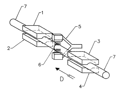
FIGURE 1 is a perspective view of coiled sucker rod
being joined in the field in accordance with the
teachings of the present method.
FIGURE 2 labelled as PRIOR ART is a detailed side
elevation view of coiled sucker rod in the process
of
being heated in accordance with conventional method.
FIGURE 3 is a detailed side elevation view of the
coiled sucker rod placed illustrated in FIGURE 1 in end
to end relation and being heated in accordance with the
teachings of the present invention.
FIGURE 4 labelled as PRIOR ART is a detailed side
elevation view of coiled sucker rod treated by
conventional welding methods after bulge formation.
FIGURE 5 is a detailed side elevation view of the
coiled sucker rod placed illustrated in FIGURE 1 a fter
bulge formation.
DETAILED DESCRIPTION OF THE PREFERRED EMBODIMENT
The preferred method will now be described with
reference to FIGURES 1 through 5.
Referring to Figure 1 two ends of coiled sucker rod 7 are
held between stationery jaws l, 2 and movable jaws 3, 4.
Abutting ends 6 of rods 7 are in full contact, and multi-
CA 02404575 2002-09-23
4
nozzle burner 5 is in position for heating rod ends 6. After
the desired temperature is reached, movable jaws 3, 4 will
start moving toward stationery jawsl, 2 in direction D,
compressing ends of rods 6, and welding two parts of rod 7 in
to one rod.
Figure 2 shows heated area of welded rods when welded using
known methods, in contrast, Figure 3 shows heated area of
welded rods when welded using new method. Figure 4 shows the
bulge formed on a welded rod when welded using known methods,
in contrast, Figure 5 shows the bulge formed on welded rod
when welded using new method.
The method, as will be hereinafter described, provides
a reliable method of joining parts of a coiled sucker rod in
the field without the need for expensive and cumbersome
equipment. Furthermore, this method allows the doing of many
welds without the need for accessing an electrical power
source for recharging batteries. In this invention the source
of energy used to weld the metal rods is a flammable gas
instead of an electrical power source. This means that
batteries and a heavy-duty electrical switch for switching
the welding current, as well as a compressor supplying the
air to operate the electric power switch, is eliminated. A
welding machine can be much simpler, lighter and less
expensive and require negligible maintenance in comparison
with a flash-butt welder. In accordance with this gas
pressure welding process, the parts of a coiled sucker rod
can be welded with the tensile properties and elongation of
the welded joint being similar to those of joints resulting
from welding with a flash-butt welder. Methods of welding
similar to this invention have been used to join reinforcing
bars for concrete, mostly in Japan. The steel, which is used
CA 02404575 2002-09-23
for a coiled sucker rod is one of much higher tensile
strength than the steel used for concrete reinforcing bars,
and using known methods of welding did not bring satisfactory
results with the coiled sucker rod. Welding steel of higher
5 strength and at the same time obtaining higher quality welds
than those in concrete reinforcing bars presents special
problems and requires a different approach. A high quality
weld is essential, especially because the sucker rod, unlike
concrete reinforcing bars, is exposed to a continuous cycling
load. One of the differences between known methods and this
new method is that in this method any possible undesirable
inclusions in the weld are completely eliminated. This is
done by eliminating the space between the ends of the rods to
be welded, and also by completing welds with a large, narrow
bulge. In other known methods of gas pressure welding instead
of attempting to completely eliminate the air space between
welded rod ends, a strongly carbonizing flame and
introduction of additional acetylene through an extra nozzle
is used during the first part of the welding cycle in order
to prevent oxidation of said rod ends. In this invention
there is no need for strongly carbonizing flame, nor for
introduction of additional acetylene, and so there is no
introduction of any additional carbon which may possibly
(beside preventing oxidation of faces of welded rod)
negatively affect chemical composition and in turn also
quality of a weld.
The heated area of the welded rod in this method is quite
narrow as shown in Fig.3 as compared to the area heated with
oscillating flame in known methods as shown in Fig.2. As a
result of heating narrow part of a rod to a higher
temperature than used in previous methods, the bulge formed
in the weld is also narrower and higher as shown in Fig.5,
compared to a weld done using known method in Fig.4. The
relatively narrow bulge, containing most of the metal from
CA 02404575 2002-09-23
6
the abutting faces of welded rods and possibly some
contaminations, is removed after welding. In known methods
the finished weld contains most of the metal from abutting
faces and possibly some undesirable contaminations. Other
differences are in the temperature used for welding, and the
welding cycle itself. The temperature used in this method,
reaching 1450°C, is higher than temperatures used in known
methods. The welding cycle in this invention does not include
variation of pressure used to compress the ends of the welded
rods, or variation in width of the heated area of the welded
rod as are used in other known methods, and thus said cycle
can be very easy control:Led.
This invention provides a method for butt-welding of a
coiled sucker rod, comprising of: preparation of the
faces of two steel rods to be welded, said preparation
has to assure that the faces of said rods are perfectly
parallel and clean and there is no space at all between
abutting ends of said rods (this can be achieved for
example with abrasive cut-off wheel or a similar saw,
located directly on the welding machine, and by cutting
the ends of said rods already clamped in the welding
jaws); bringing clamped ends of said rods in full
contact; preheating a minimum length, which will vary
depending on ambient temperature from 2 to 10 inches,
of each rod end to temperature which will vary
depending on ambient temperature from 150~C to 300~C, in
order to slow down cooling of the future weld
positioning the burner above said rod ends and heating
of said rods ends up to a temperature at which surface
of the abutting ends of welded rods starts to melt;
applying a pressure of minimum 17 kg/mmz to said of rod
crossection to compress the ends of the welded rods,
while continuing heating; discontinuing heating when
the bulge in the joint of said welded bars reaches a
CA 02404575 2002-09-23
7
height equal to or greater than one third of the
diameter of the welded rod, while keeping said
pressure: enclosing said weld in the thermal insulation
to slow cooling of the weld and prevent forming brittle
structure of the weld due to quick cooling, immediately
after the heating flame is shut of: letting said weld
cool down to ambient temperature.
Some of the materials used for a coiled sucker rod, such as
steel 4330M and similar materials, need to be heat-treated
after welding in order to improve their mechanical
properties. In the preferred method of heat-treatment the
weld is reheated up to temperature just below the grain size
transformation range, temperature between 570°C to 600°C and
kept at this temperature for approximately 20 minutes, then
allowed to slowly cool to ambient temperature.
Burners comprising rows of nozzles facing each other or
arranged in a circle are used to heat the abutting ends of
the welded rods. Acetylene and oxygen is usually used for
heating, but other hydrocarbon gases may be used.
In this patent document, the word "comprising" is used in
its non-limiting sense to mean that items following the word
are included, but items not specifically mentioned are not
excluded. A reference to an element by the indefinite
article "a" does not exclude the possibility that more than
one of the element is present, unless the context clearly
requires that there be one and only one of the elements.
It will be apparent to one skilled in the art that
modifications may be made to the illustrated embodiment
without departing from the spirit and scope of the
invention as hereinafter defined in the Claims.