Note : Les descriptions sont présentées dans la langue officielle dans laquelle elles ont été soumises.
CA 02414655 2002-12-17
TRACTION BAND AND SPROCKET FOR VEHICLES
Field of invention
This invention relates to an endless traction band and sprocket wheel that are
used to
propel vehicles and more particularly snowmobiles.
Background of the invention
The present invention relates to an endless traction band for a snowmobile and
to the
sprocket wheel used therewith. Such a traction band is designed to travel on
snow, on
which the use of wheeled vehicle is of little help.
A traction band is usually made of a reinforced molded rubber material or an
assembly of interconnected parts that form an endless. band, having
longitudinally
spaced and transversely disposed stiffeners embedded in the rubber material.
The
endless band is flexible around a lateral axis so that it can follow the
curvature around
sprocket and idler wheels. Each traction band is designed to support a
significant
portion of the total weight of the vehicle and apply a traction force on the
ground.
As used herein, the term "rubber" relates to any elastic and primarily non-
metallic
materials such as rubber, elastomers, or combinations thereof used in the
manufacture
of endless traction bands.
30
Among all off road vehicles equipped with traction bands, recreational
snowmobiles
are unique in that they are equipped with only one traction band while
essentially all
other vehicles are equipped with two or more traction bands. Examples of such
other
vehicles are bulldozers, military tanks, snow-surfacing machines, etc.
Without excluding any other applications, traction bands for vehicles
traveling at
moderate or high speeds, which are essentially snowmobiles, are the prime
interest of
the present invention. The snowmobiles are then used in the present
description as the
main application for the traction bands and the method in accordance with the
present
invention.
2
CA 02414655 2002-12-17
A snowmobile is often equipped with a rubber-band traction band that features
an
endless body made of a reinforced rubber material with longitudinally spaced
and
transversely disposed stiffeners embedded in the rubber material. The body
typically
defines a longitudinally extending central portion and a, pair of lateral band
portions
each of which is located on one of the sides of the central portion. The
traction band
is positioned under the chassis of the snowmobile and supports most of the
weight. A
pair of front ski-like runners are provided to steer the snowmobile and
support the
other portion of the weight.
The body of the traction band has a ground-engaging oul:er side and an inner
side. The
inner side cooperates with a suspension system. The weight of the traction
band is
supported by either a pair of slide rails or a plurality of bogey wheels that
are
mechanically connected to the other parts of the suspension system. The
suspension
system is also used to support the traction band with respect to lateral
movements.
The ground-engaging outer side has a tread pattern that is repeated uniformly
or not
over the entire length of the traction band. The tread pattern comprises a
plurality of
projecting traction lugs that are configured and disposed in accordance with
the
purpose for which the traction band is designed. The traction lugs are used to
increase
the adherence of the snowmobile on snow mud, melting snow, ice or any other
similar
surfaces.
Further, the opposite lateral band portions are usually separated from the
central
portion by a corresponding row of holes. Each row of holes generally
cooperates with
the teeth of the corresponding sprocket wheels and idler wheels or simply
provide a
support area for metal clip.
The ground-engaging outer side usually has a sequence of profiles that is
repeated
uniformly or not over the total length of the traction band. Each sequence of
profiles
or tread pattern comprises laterally extending profiles that are
longitudinally spaced
apart by flat areas. Each profile comprises a series of outwardly projecting
traction
lugs. The choice of lug profiles that are selected to be part of every
sequence of
profiles, which is repeated along the circumference of the traction band, has
an
3
CA 02414655 2002-12-17
influence on the band behavior on the snow, on the snowmobile performances and
on
the comfort of the driver. These criteria are very critical in a marketing
point of view,
since they differentiate products from one another in the eye of a potential
customer.
There is always a need for a traction band which provides better performance
and
better comfort for the driver.
Summary of the invention
The object of the invention is to create an improved driving system for a
snowmobile.
It is another object to provide an improved drive sprocket for use with a
snowmobile
traction band.
It is still another object to provide a novel traction band for a snowmobile.
There is therefore provided a traction band for use with a snowmobile
comprising a
sprocket wheel having a plurality of teeth, said traction band comprising a
ground-
engaging outside surface on which are disposed a series of laterally extending
traction
lug profiles separated from each other by flat areas, each of which extend
laterally
and comprise none of the said traction lugs, said traction band further
comprising a
central longitudinally extending central band portion, wherein an opening
adapted to
receive one of said teeth extends through each flat area of said central band
portion .
In another aspect of the invention the said sprocket wheel comprises two
parallel
disks each provided with traction teeth and two holes extend through each said
central
flat area of the traction band.
Other aspects and many of the attendant advantages will be more readily
appreciated
as the same becomes better understood by reference to the following detailed
description and considered in connection with the accompanying drawings in
which
like reference symbols designated like elements throughout the figures.
4
CA 02414655 2002-12-17
The features of the present invention which are believed to be novel are set
forth with
particularity in the appended claims.
Brief description of the figures
FIG. 1 is a partial top view of a first embodiment of an endless traction band
in
accordance with the invention.
FIG. 2 is a cross-sectional view of the traction band shown in FIG. 1 in which
the
sprocket and support wheels are also shown.
FIG. 3 is an isometric view of the traction band shown in FIG. 1.
FIG. 4 is a side view of the traction band shown in FIG. 1.
FIG. 5 is a partial top view of a second embodiment of an endless traction
band in
accordance with the invention.
FIG. 6 is a cross-sectional view of the traction band shown in FIG. 5 in which
the
sprocket and support wheels are also shown.
FIG. 7 is an isometric view of the traction band shown in FIG. 5.
FIG. 8 is a side view of the traction band shown in FIG. 5.
2~
FIG. 9 is a partial top view of a third embodiment of an endless traction band
in
accordance with the invention.
FIG. 10 is a cross-sectional view of the traction band shown in FIG. 9 in
which the
sprocket and support wheels are also shown.
FIG. 11 is a side view of a sprocket wheel fn accordance with this invention.
5
CA 02414655 2002-12-17
FIG. 12 is a cross-sectional view of the sprocket wheel shown in FIG. 11.
FIG. 13 is an isometric view of the sprocket wheel shown in FIG. 11.
FIG. 14 is a side view of a support wheel in accordance with this invention.
FIG. 15 is a cross-sectional view of the support wheel shown in FIG. 14.
FIG. 16 is an isometric view of the support wheel shown in FIG. 14.
FIG. 17 is another partial top view of the traction band shown in FIG. 1.
FIG. 18 is another isometric view of the traction band shown in FIG. 1.
FIG. 19 is a side view of the traction band shown in FIG. 1 as installed over
sprocket
wheels shown in FIG. 11 and support wheels shown in FIG. 14.
Detailed description of a preferred embodiment
A traction band according to a preferred embodiment; of the present invention
is
described hereinafter and illustrated in the appended figures.
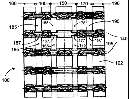
As shown in the figures, the band 100 is made of an endless body 102 of
reinforced
rubber material, with longitudinally spaced and transversely disposed
stiffeners (not
shown) that may or may not be completely embedded in the rubber material of
the
endless body 102. Figure 1 shows the body 102 which comprises a central
portion
150, two mid-band portions (160 and 170) and two lateral band portions (180
and
190) which are located on each side of the central portion 150. The central
portion
150, the mid-band portions 160 and 170 and the lateral band portions 180 and
190
longitudinally extend along the circumference of the endless body 102.
The body 102 of the band 100 has a ground-engaging outer side 108 that is
usually
made from a sequence of profiles 140 which is repeated or not over the entire
6
CA 02414655 2002-12-17
circumference of the traction band 100. Each profile 140 comprises a selection
of lugs
110 which are separated from each other by a flat area 130.
The traction band 100 shown in FIG. 1 comprises series of openings 165 and I75
in
the central longitudinally extending central band portion 150 and preferably,
series of
openings 185 and 195 in the mid-band portions 160 and 170. Any two consecutive
openings 165, 175, 185 or 195 in the same series of openings define a support
area
167, 177, 187, and 197 which can either offer support for metal clips (not
shown) or a
meshing area for a sprocket drive wheel.
The sprocket drive wheel is formed of two disks 210 and 220 each having a
series of
teeth 215 and 225 are disposed on the inner side of the band such that the
teeth 215
and 225 extend sequentially through each opening of said series 165 and 175.
1 ~ The disks 210 and 220 may be preferably made of plastic or any another
similar
material. Figure 11, 12 and 13 illustrates how the series of teeth 215, 225
are off
centred from the central vertical plane of the disk 210, 220, therefore
providing space
for a cylindrical root area 217 and 227.
A plurality of support wheels 310 and 320 are disposed on the inside of the
traction
band to support the band 100 and the vehicle. A series of guiding lugs 120 are
placed
on the inside of the traction band to help maintain the traction band on the
support
wheels 310 and 320.
For snowmobiles which are equipped with an endless rubber traction band 100,
the
capacity to offer to the users a smooth and stable ride with the minimum of
noise and
vibration levels represents one of the characteristics that is most
appreciated by
customers. On top of that, the traction band 100 has a lesser weight since
more series
of openings 165, 175, 185, 195 are required and the band 100 also has a lower
cost
since less material is required to produce it.
In the preferred embodiment shown in Figure 1, 2, 3 and 4, the sprocket drive
wheel
cooperates with the central band portion 150. In each disk 210 and 220, the
7
CA 02414655 2002-12-17
cylindrical root area 217 offers a support to the traction band 100 and help
maintain
its circularity as it rotates. This configuration generally helps lower the
vibration
levels of the traction band and therefore reduce the generated noise. This
phenomenon
is partly explained by the fact that the typical root area in between two
consecutive
S teeth, which are usually centred in a vertical plane with respect to the
disk, can not
offer a continuous support area to the traction band 100 as it rotates.
Preferably, no metal clips (not shown), are located in the support areas 167,
177 of the
central band portion 1 S0, therefore minimizing the level of generated noise
as the
series of teeth 21 S, 22S mesh with the support areas 167, 177. In the
preferred
embodiment, the support areas 187, 197 in the mid-band portions 160, 170 offer
support to metal clips (not shown) to provide a sliding surface for the
traction band,
without producing high level of noises that are sometimes associated with the
use of
metal clips (not shown).
1S
Figure 9 and 10 illustrate another embodiment of this invention, which
comprises a
central band portion 2S0 and two lateral band portions 280, 290. The central
band
portion 2S0 comprises a series of openings 26S and 275. Any two consecutive
openings 265, 27S in the same series of openings define a support area 267,
277,
which each comprises a mesh area 268, 278 and a clip area 269, 279. Metal
clips (not
shown) are located on the clip area 269, 279 to provide a sliding surface to
the
traction band 100 and the series of teeth 21 S, 22S cooperate with the clip-
less mesh
areas 268, 278.
Although a preferred embodiment of the invention has been described in detail
herein
and illustrated in the accompanying figures, it is to be understood that the
invention is
not limited to this precise embodiment and that various changes and
modifications
may be effected therein without departing from the scope or spirit of the
present
invention.
8