Note : Les descriptions sont présentées dans la langue officielle dans laquelle elles ont été soumises.
CA 02427302 2003-04-30
SANITIZING CABINET FOR SPORTS EQUIPMENT
FIELD OF THE INVENTION
The present invention relates to an apparatus and a method for treating sports
gear
to sanitize the same.
BACKGROUND OF THE INVENTION
The problem of odors, mold, and mildew associated with sports equipment is
common. Thus, u~Thile clothing and apparel can be washed and dried in a normal
manner,
much equipment cannot be subject to these processes. For example, in the sport
of
hockey, skates and protective pads and other paraphernalia cannot be put in
commercial
washers and dryers. Similarly, shoes and pads from other sports such as soccer
and
basketball cannot be washed and dried in a conventional manner.
It is known in the art, as shown in U.S. Patent 5,369,893, that one may use
self
contained dryers for accommodating sports equipment. The dryers have walls
which
cause heated air to recirculate in the drying chambers to decrease the
moisture content of
the air and increase the drying energy efficiency. Blowers and fans associated
with
electric heaters operate to circulate heated air through the drying chambers.
U.S. Patent 5,369,892 discloses a chest or foot locker structure with a rigid
housing wherein the top of the housing has a cover movable to an open position
to allow
access to the drying chamber. A motor driven fan located in an air mixing
chamber
within the housing draws air through a filter into the drying chamber. Air
porous walls
within the drying chamber allow air to mix the drying chamber back to the air
mixing
chamber for recirculation back into the drying chamber. Air also flows out of
the drying
chamber through a filter having activated charcoal to remove odors from the
air
-2-
CA 02427302 2003-04-30
discharged into the environment. This dryer utilizes an internal motor and fan
associated
with the electric heater and specialized porous walls within a housing.
U.S. Patent 6,134,806 discloses a portable sports equipment bag having an air
distributor which is connected with a hose to a blower and ozone generator
operable to
move air and ozone under pressure into the air distributor. The air
distributor's one or
more manifolds located within the bag, the manifolds having a plurality of
apertures to
allow,air and ozone in the manifolds to flow into the bag to dry sports
equipment and
objects within the bag. There are air filters mounted on the bag to remove
odors and
foreign matters from the air flow from the bag into the environment.
U.S. Patent 6,263,591 discloses a portable sports equipment drying container
comprising a body having a cover with an input fan mounted in one of the side
walls and
an output fan mounted in another one of the walls. The fans are used for
drying the
moisture wet clothes and equipment placed in the container for circulating air
through the
container.
However, none of the prior art deals with the necessity of providing a
completely
sealed enclosure while using ozone for sanitization purposes. In this respect,
there are
regulations in most countries mandating that ozone cannot be created and
vented to the
atmosphere.
While the above patents do teach various apparati and methods for attempting
to
clean and sanitize sports equipment, there exists a need for an apparatus and
method
which can be used on a commercial basis for sanitizing sports equipment.
SUM1VIARY OF THE INVENTION
It is an object of the present invention to provide a method and apparatus
which
-3-
CA 02427302 2003-04-30
would sanitize sports equipment and which method and apparatus is suitable for
use on a
commercial basis and is environmentally friendly.
According to one aspect of the present invention, there is provided an
apparatus
for sanitizing sports equipment comprising, a cabinet having an access opening
thereto,
means for sealing the access opening to provide a substantially airtight
cabinet,
means for generating ozone and means for causing the ozone to circulate within
the
cabinet.
According to a further aspect of the present invention, there is provided a
method
of sanitizing sports equipment, the method comprising the steps of placing the
sports
equipment within a closed cabinet, circulating ozone containing air in a first
direction
through the cabinet for a first period of time, circulating the ozone
containing air in a
second direction opposite to the first direction through the cabinet for a
second period of
time, the ozone containing air having an ozone concentration of at least 20
ppm,
stopping all circulation of the air and ozone for a period of time sufficient
for the ozone
concentration to diminish to less than 3 ppm, and removing the sports
equipment from
the cabinet.
Preferably, the cabinet is provided with means for securely sealing the same
during the period of time when ozone containing air is within the cabinet. The
tight
sealing is required to prevent the escape of ozone and the possibility of
environmental
damage.
The walls of the cabinet can be formed of a transparent or opaque material
resistant to ozone deterioration. Within the cabinet are means for accepting
sports
equipment, and in one embodiment, foraminous shelves ma~J be provided.
Naturally,
_q._
CA 02427302 2005-08-12
hooks and other types of retainers may be utilized for any specialized
equipment.
A preferred means of circulating the ozone containing air through the cabinet
preferably comprises a pair of reversible fans located within the bottom wall
of the
cabinet defining the space for receiving the sports equipment. Such fans are
known in
the art and need not be described and detailed herein.
Preferably, the apparatus also includes means for spraying a fluid and
preferably a
liquid containing a product which will assist in depleting the ozone in the
cabinet.
In operation, the sports equipment to be sanitized is placed within the
cabinet and
the access opening closed. Subsequently, ozone containing air is circulated in
a first
direction throughout the cabinet from the first one of said conduits and exits
through a
second one of said conduits. This is continued for a period of time which, in
the
preferred embodiment, would range between 3 and 9 minutes.
Subsequently, the ozone containing air is circulated in a second direction
from the
second conduit and exiting through the first conduit. This is continued for a
period of
time which preferably is similar to those times in which it is circulated in a
first direction.
Subsequently, an agent is lightly sprayed in a mist and the cabinet is
maintained
closed for a period of time (generally between 1 and 5 minutes) sufficient for
the ozone
level to go down to at least 3 ppm and preferably below 2 ppm. The cabinet can
then be
opened and the sports equipment removed.
As aforementioned, preferably an ozone depleting agent is sprayed into the
cabinet. While there are many compounds and compositions which are known to
function as an ozone depleter, a particularly preferred embodiment utilizes a
tea tree oil
also know as a melaleuca oil. The advantage of such an oil is that it acts as
a disinfectant.
-5-
CA 02427302 2003-04-30
also know as a melaleuca oil. The advantage of such an oil is that it acts as
a disinfectant.
In a preferred embodiment of the invention, the ozone depletion agent may be
placed on a container and there may be provided means to ensure that the agent
is
dispersed a certain time prior to opening of the doors. Such control means are
well
known in the art and may include suitable timers and interlocks, as well as
means to
ensure that the ozone depleting agent is present in the container.
BRIEF DESCRIPTION OF THE DRAWINGS
Having thus generally described the invention, reference will be made to the
accompanying drawings illustrating an embodiment thereof, in which:
Figure 1 is a perspective view of a sanitizing cabinet according to an
embodiment
of the present invention; and
Figure 2 is a front elevational view thereof illustrating use of the
sterilizing
cabinet.
DESCRIPTION OF THE PREFERRED EMBODIMENTS
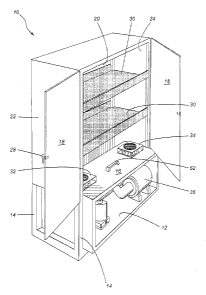
As shown in Figures 1 and 2, there is provided a sterilizing cabinet which is
generally designated by reference numeral 10. Sterilizing cabinet 10 includes
a base
member 12 and four structural uprights 14 extending upwardly therefrom.
A compartment is defined by a compartment floor 1 i5, a front panel 18, a rear
panel 20, and a pair of side panels 22, 24. As will be seen in Figure l, a
pair of front
panels 18 are hingedly connected. When closed, a locking handle 28 is designed
to
engage the other front panel 18 to maintain the compartment tightly sealed.
Placed within sanitizing cabinet I O above floor 16 are a pair of foraminous
shelves
30. Foraminous shelves 30 may be of various types of structures, either a mesh
or using
-s-
CA 02427302 2003-04-30
wires.
Mounted in floor I6 is a first fan assembly 32 which is adjacent side wall 22
and a
second fan assembly 34 which is adjacent side panel 24.
Mounted in the lower portion of sanitizing cabinet 10 below floor 16 is an
ozone
generator 36.
A first conduit 38 is in fluid communication with first fan assembly 32 while
a
second conduit 40 is in fluid communication with second fan assembly 34. A
connecting
conduit 42 is connected to ozone generator 36 and is designed to supply both
first
conduit 38 and second conduit 40.
A reservoir 44 is provided to contain a supply of an ozone depleting agent
having
one or more additives therein. The water is connected via conduits 46 to spray
heads 48
mounted in the upper portion of the sanitizing cabinet 10. A control panel
(not shown)
may contain conventional control circuitry including timers and interlocks. In
this
respect, there is provided a scale 60 which is designed to continually monitor
the weight
of reservoir 44 to ensure that the ozone depleting agent is present in a
quantity sufficient
to be sprayed within the cabinet. Naturally, other methods such as sensors
within the
reservoir 44 may be utilized. In all instances, lack of the presence of the
ozone depleting
agent would not permit operation of the apparatus.
In operation, and as shown by arrows 50, first fan assembly 32 is driven in a
first
direction to circulate the ozone containing air from first conduit 38 to a
second conduit
40. Subsequently, the direction of circulation is reversed by reversing the
directions of
first and second fan assemblies 32 and 34 respectively as shown by arrows 52..
It will be
noted that the ozone containing air circulates throughout the cabinet in order
to assure
_'7_
CA 02427302 2003-04-30
that it contacts all the equipment placed therein.
The bottom may be removed as a unit by means of handle 62 to facilitate
servicing.
It will be understood that the above described embodiment is for purposes of
illustration only and that changes or modifications may be made thereto
without departing
from the spirit and scope of the invention.
_g_