Sélection de la langue

Search

Sommaire du brevet 2429153 

Énoncé de désistement de responsabilité concernant l'information provenant de tiers

Une partie des informations de ce site Web a été fournie par des sources externes. Le gouvernement du Canada n'assume aucune responsabilité concernant la précision, l'actualité ou la fiabilité des informations fournies par les sources externes. Les utilisateurs qui désirent employer cette information devraient consulter directement la source des informations. Le contenu fourni par les sources externes n'est pas assujetti aux exigences sur les langues officielles, la protection des renseignements personnels et l'accessibilité.

Disponibilité de l'Abrégé et des Revendications

L'apparition de différences dans le texte et l'image des Revendications et de l'Abrégé dépend du moment auquel le document est publié. Les textes des Revendications et de l'Abrégé sont affichés :

  • lorsque la demande peut être examinée par le public;
  • lorsque le brevet est émis (délivrance).
(12) Brevet: (11) CA 2429153
(54) Titre français: MECANISME DE STYLO AUTO-RETRACTABLE A EFFET D'AMORTISSEMENT
(54) Titre anglais: AUTO-RETRACTABLE PEN MECHANISM WITH A CUSHION EFFECT
Statut: Réputé périmé
Données bibliographiques
Abrégés

Abrégé français

~ Stylo rétractable comprenant un stylo et un capuchon. Le stylo comprend un boîtier creux, une cartouche d'encre, un ressort mécanique et un élément magnétique mobile. Le capuchon comprend un corps de capuchon et un aimant permanent immobile. Le stylo peut se fixer au capuchon par la force d'attraction magnétique exercée par une seule main lorsqu'un utilisateur place l'élément magnétique mobile du stylo à proximité de l'aimant permanent immobile du capuchon. La pointe d'écriture de la cartouche d'encre du stylo se rétracte dans le boîtier creux du stylo quand une force d'attraction magnétique exercée vers le haut est supérieure à une force d'expansion mécanique exercée vers le bas. Cette invention concerne les stylos, et la principale utilisation de l'invention concerne l'opération d'un stylo à une seule main.


Abrégé anglais

~ A retractable pen comprises a pen and a cap. The pen comprises a hollow case, an ink cartridge, a mechanical spring and a mobile magnetic element. The cap comprises a cap body and a stationary permanent magnet. The pen is capable of attaching to the cap by the magnetic attraction force in a single-hand operation when a user places the mobile magnetic element of the pen in proximity to the stationary permanent magnet of the cap. The writing tip of the ink cartridge of the pen retracts into the hollow case of the pen when an upward magnetic attraction force is greater than a downward mechanical expansion force. This invention relates to pens, and the principal use of the invention is for operating a pen with a single hand.

Revendications

Note : Les revendications sont présentées dans la langue officielle dans laquelle elles ont été soumises.


Claims

~ The embodiments of the invention in which an exclusive property or
privilege is claimed are defined as follows:

1. A retractable pen comprising:
~ a pen comprising:
~ a hallow case having a closed end, a narrow middle portion
and an open conical end;
~ an ink cartridge having a top end, a fat portion and a
writing tip, the ink cartridge movably mounted inside the
hollow case, the writing tip of the ink cartridge being
capable of penetrating through the open conical end of the
hollow case;
~ a mechanical spring for downwardly biasing the ink
cartridge, the mechanical spring concentrically mounted
around the ink cartridge between the narrow middle portion
of the hollow case and the fat portion of the ink cartridge;
and
~ a mobile magnetic element securely attached to the top end
of the ink cartridge; and
~ a cap comprising:
~ a cap body having a top end and a bottom end; and
~ a stationary permanent magnet for providing a magnetic
attraction force, the stationary permanent magnet securely
attached to the bottom end of the cap body;
the pen being capable of attaching to the cap by the magnetic
attraction force in a single-hand operation when a user places
the mobile magnetic element of the pen in proximity to the
stationary permanent magnet of the cap, the writing tip of the
ink cartridge of the pen retracting into the hollow case of the
pen when an upward magnetic attraction force between the mobile
magnetic element of the pen and the stationary permanent magnet
of the cap is greater than a downward mechanical expansion force
by the mechanical spring of the pen.

2. A retractable pen as defined in claim 1, in which the downward
mechanical expansion force by the mechanical spring of the pen provides
a cushion effect to the writing tip of the ink cartridge of the pen.

3. A retractable pen as defined in claim 2, further comprising:
~ a loop-shaped cord securely attached to the top end of the cap
body of the cap.

4. A retractable pen as defined in claim 1, further comprising:
~ a pocket clip securely attached to the top end of the cap body of
the cap.

5. A retractable pen as defined in claim 1, in which the hollow case of
the pen is cylindrical.


6. A retractable pen as defined in claim 1, in which the mobile magnetic
element of the pen is disc-shaped.

7. A retractable pen as defined in claim 1, in which the mobile magnetic
element of the pen is ring-shaped.

8. A retractable pen as defined in claim 1, in which the mobile magnetic
element of the pen is made of a rare-earth permanent magnet.

9. A retractable pen as defined in claim 1, in which the mobile magnetic
element of the pen is made of a ferromagnetic material.

10. A retractable pen as defined in claim 1, in which the cap body of the
cap is cylindrical.

11. A retractable pen as defined in claim 1, in which the stationary
permanent magnet of the cap is disc-shaped.

12. A retractable pen as defined in claim 1, in which the stationary
permanent magnet of the cap is ring-shaped.

13. A retractable pen as defined in claim 1, in which the stationary
permanent magnet of the cap is made of a rare-earth permanent magnet.

14. A retractable pen as defined in claim 1, in which the stationary
permanent magnet of the cap is exposed.

15. A retractable pen as defined in claim 1, in which the ink cartridge of
the pen is a ball-point pen.

16. A retractable pen as defined in claim 1, in which the ink cartridge of
the pen is a gel-ink pen.

Description

Note : Les descriptions sont présentées dans la langue officielle dans laquelle elles ont été soumises.


CA 02429153 2003-05-17
Description
Title
o Auto-Retractable Pen Mechanism with a Cushion Effect
Technical Field
o This invention relates to pens, more particularly to a retractable pen.
Background Art
o There are many instances where it would be desirable to be able to
provide a retractable pen with a mechanism to allow a user to
magnetically attach a pen to a cap in a single-hand operation, and to
simultaneously retract the writing tip.
o A number of patents disclose retractable pens.
o U.S. Patent 6 394 677 discloses "Hanging per. and card thereof". This
prior art pen has a pen cap, and a penholder. fhe pen cap has a
blocking cover with a loop cord for carrying and an opening at the
other end. The penholder provides a center stick therein with a writing
head of the center stick extending outwardly from a conical part at an
end of the penholder. A magnetic ring is fixed in the pen cap. The
conical part is made of magnet inducing material. The pen cap engages
the penholder by way of the magnetic ring attracting the conical part
when the conical part is inserted into the pen cap from the open end.
o These prior art arrangements do not provide a retractable pen with a
mechanism to allow a user to magnetically attach a pen to a cap in a
single-hand operation. In addition, prior art retractable pens do not
simultaneously retract the writing tip when the pen is attached to the
cap. Moreover, prior art retractable pens do not provide a cushion
effect to the writing tip.
l~escri.ption of the Invention
o It is a primary object of the invention to provide a retractable pen in
which a pen magnetically attaches to a cap in a single-hand operation
by the user.
o It is another object of the invention to provide a retractable pen
which simultaneously retract the writing tip when the pen is attached
to the cap.
o It is another object of the invention to provide a retractable pen in
which the pen stays upside up and downside down when attached to the
cap.
o It is another object of the invention to provide a retractable pen
which has a cushion effect.
o It is another object of the invention to provide a retractable pen
which has a loop-shaped cord to be worn by the user around his/her
neck.
o A retractable pen comprises a pen and a carp. The pen comprises a hollow
case, an ink cartridge, a mechanical spring and a mobile magnetic
element. The cap comprises a cap body and a stationary permanent
magnet. The pen is capable of attaching to the cap by the magnetic


CA 02429153 2003-05-17
attraction force in a single-hand operation when a user places the
mobile magnetic element of the pen in proximity to the stationary
permanent magnet of the cap. The writing tip of the ink cartridge of
the pen retracts into the hollow case of the pen when an upward
magnetic attraction force is greater than a downward mechanical
expansion force.
Brie~ Description of the Figures in the Drainrings
o In drawings which illustrate embodiments of the invention:
o Figure 1 marked "Prior Art" is a sectional view of a
conventional wearable pen in a detached position;
o Figure 2 marked "Prior Art" is a sectional view of another
conventional wearable pen in a detached position;
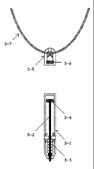
o Figure 3 is a sectional view of one embodiment of a retractable
pen in a detached position according to the invention;
o Figure 4 is a sectional view of the invention in an attached
position; and
o Figure 5 is a sectional view of another embodiment of a
retractable pen in an attached position according to the
invention.
Modes far Carrya.ng Out the Invention
o A conventional wearable pen shown in Figure 1 marked "Prior Art"' in a
detached position comprises a pen and a neck cord.
o The pen comprises a pen body 1-1. The pen body 1-1 of the pen has a
closed end, a middle portion and a writing tip. The middle portion of
the pen body 1-1 forms a female part 3.-2.
o The neck cord comprises a loop-shaped cord 1-5 and a cap body 1-3. The
cap body 1-3 has a top portion and an open bottom portion. The top
portion of the cap body 1-3 is securely attached to the loop-shaped
cord 1-5. The open bottom portion. of the c:ap body 1-3 forms a male
part 1-4 for providing a mechanical engagement force.
o The female part 1-2 of the pen is capable of engaging with the male
part 1-4 of the neck cord by the mechanical engagement force when a
user inserts the pen into the cap body 1-~ of the neck cord. The female
part 1-2 of the pen is capable of detaching from the male part 1-4 of
the neck cord when a user applies a force greater than the mechanical
engagement force between the female part 1-2 of the pen and the male
part 1-4 of the neck cord.
o Another conventional wearable pen shown in Figure 2 marked "Prior
Art" in a detached position comprises a pe:n and a neck cord.
o The pen comprises a pen body 2-1. The pen body 2-1 of the pen has a
closed end, a conical portion and a writing tip. The conical portion of
the pen body 2-1 comprises a ferromagnetic element 2-2.
o The neck cord comprises a loop-shaped cord 2-5, a cap body 2-3, and a
permanent magnet 2-4 for providing a magnetic attraction force. The cap
body 2-3 has a top portion and an open bottom portion. The top portion
of the cap body 2-3 is securely attached to the loop-shaped cord 2-5.
The permanent magnet 2-4 is securely mounted inside the cap body 2-3.


CA 02429153 2003-05-17
o The ferromagnetic element 2-2 of the pen is capable of attaching to the
permanent magnet 2-4 of the neck cord by the magnetic attraction force
when a user inserts the pen into the cap body ~-3 of the neck cord. The
ferromagnetic element 2-2 of the pen is capable of detaching from the
permanent magnet 2-4 of the neck cord when a user applies a force
greater than the magnetic attraction force between the ferromagnetic
element 2-2 of the pen and the permanent magnet 2-4 of the neck cord.
o These prior art pens do not provide a wearable pen in which a pen
attaches to a neck cord in a single-hand operation because of the need
to align the pen for insertion into the cap body. In addition, because
the conventional wearable pen is hung upside down, it is necessary that
the prior art pen be a so-called Space Pen (Trade Mark), comprising a
hermetically-sealed ink cartridge filled with pressurised gas in order
to avoid ink leakage.
o In one embodiment of the invention shown in Figure 3 in a detached
extended position, Figure 4 in a.n attached retracted position and
F3.gure 5 in an attached retracted position, a retractable pen
comprises a pen and a cap.
o The pen comprises a hollow case 3-1, an i:nk cartridge 3-2, a
mechanical spring 3-3 for downwardly biasing the ink cartridge 3-2,
and a mobile magnetic element 3-~.
o The hollow case 3-1 of the pen has a closed end, a narrow middle
portion and an open conical end.
o The ink cartridge 3-2 of the pen has a top end, a fat portion and a
writing tip. The ink cartridge 3-2 is movably mounted inside the hollow
case 3-1. The writing tip of the ink cartridge 3-2 is capable of
penetrating through the open conical end of the hollow case 3-1.
o The mechanical spring 3-3 of the pen is concentrically mounted around
the ink cartridge 3-2 between the narrow middle portion of the hollow
case 3-1 and the fat portion of the ink cartridge 3-2.
o The mobile magnetic element 3-4 of the pen is securely attached to the
top end of the ink cartridge 3-2.
o The cap comprises a cap body 3-5 and a stationary permanent magnet 3-6
for providing a magnetic attraction force.
o The cap body 3-5 of the cap has a top end and a bottom end.
o The stationary permanent magnet 3-6 of the cap is securely attached to
the bottom end of the cap body 3-5.
o The pen is capable of attaching to the cap by the magnetic attraction
force in a single-hand operation when a user places the mobile magnetic
element 3-4 of the pen in proximity to the stationary permanent magnet
3-6 of the cap. The writing tip of the ink cartridge 3-2 of the pen
retracts into the hollow case 3-1 of the pen when an upward magnetic
attraction force between the mobile magnetic element 3-4 of the pen and
the stationary permanent magnet 3-6 of the cap is greater than a
downward mechanical expansion force by the mechanical spring 3-3 of the
pen.
o The downward mechanical expansion force by the mechanical spring 3-3 of
the pen may provide a cushion effect to the writing tip of the ink
cartridge 3-2 of the pen.


CA 02429153 2003-05-17
o The retractable pen may further comprise a loop-shaped cord 3-7
securely attached to the top end of the cap body 3-5 of the cap.
o The retractable pen may further comprise a pocket clip 3-8 securely
attached to the top end of the cap body 3-5 of the cap.
o The hollow case 3-1 of the pen may be cyl.indri.cal.
o The mobile magnetic element 3-4 of the pen may be disc-shaped or
ring-shaped.
o The mobile magnetic element 3-4 of the pen may be made of a rare-earth
permanent magnet. Alternatively, the mobile magnetic element 3-4 of the
pen may be made of a ferromagnetic material.
o The cap body 3-5 of the cap rnay be cylindrical.
o The stationary permanent magnet 3-6 of the cap may be disc-shaped or
ring-shaped.
o The stationary permanent magnet 3-6 of the cap may be made of a
rare-earth permanent magnet.
o The stationary permanent magnet 3-6 of the cap may be exposed.
o The ink cartridge 3-2 of the pen may be a ball-point pen, or a gel-ink
pen.
o The magnetic attraction force between the mobile magnetic element 3-4
of the pen and the stationary permanent magnet 3-6 of the cap provides
self-alignment between the hollow case 3-7. of the pen and the cap body
3-5 of the cap.

Dessin représentatif
Une figure unique qui représente un dessin illustrant l'invention.
États administratifs

Pour une meilleure compréhension de l'état de la demande ou brevet qui figure sur cette page, la rubrique Mise en garde , et les descriptions de Brevet , États administratifs , Taxes périodiques et Historique des paiements devraient être consultées.

États administratifs

Titre Date
Date de délivrance prévu 2005-08-16
(22) Dépôt 2003-05-17
Requête d'examen 2004-09-27
(41) Mise à la disponibilité du public 2004-11-17
(45) Délivré 2005-08-16
Réputé périmé 2014-05-20

Historique d'abandonnement

Il n'y a pas d'historique d'abandonnement

Historique des paiements

Type de taxes Anniversaire Échéance Montant payé Date payée
Le dépôt d'une demande de brevet 150,00 $ 2003-05-17
Taxe de maintien en état - Demande - nouvelle loi 2 2005-05-17 50,00 $ 2003-12-23
Requête d'examen 400,00 $ 2004-09-27
Taxe finale 150,00 $ 2005-06-02
Taxe de maintien en état - brevet - nouvelle loi 3 2006-05-17 50,00 $ 2005-12-19
Taxe de maintien en état - brevet - nouvelle loi 4 2007-05-17 50,00 $ 2007-01-10
Taxe de maintien en état - brevet - nouvelle loi 5 2008-05-19 100,00 $ 2008-01-11
Taxe de maintien en état - brevet - nouvelle loi 6 2009-05-18 100,00 $ 2009-01-14
Taxe de maintien en état - brevet - nouvelle loi 7 2010-05-17 100,00 $ 2010-01-01
Taxe de maintien en état - brevet - nouvelle loi 8 2011-05-17 100,00 $ 2011-01-02
Taxe de maintien en état - brevet - nouvelle loi 9 2012-05-17 100,00 $ 2012-01-01
Titulaires au dossier

Les titulaires actuels et antérieures au dossier sont affichés en ordre alphabétique.

Titulaires actuels au dossier
SUNATORI, GO SIMON
Titulaires antérieures au dossier
S.O.
Les propriétaires antérieurs qui ne figurent pas dans la liste des « Propriétaires au dossier » apparaîtront dans d'autres documents au dossier.
Documents

Pour visionner les fichiers sélectionnés, entrer le code reCAPTCHA :


Pour visualiser une image, cliquer sur un lien dans la colonne description du document. Pour télécharger l'image (les images), cliquer l'une ou plusieurs cases à cocher dans la première colonne et ensuite cliquer sur le bouton "Télécharger sélection en format PDF (archive Zip)" ou le bouton "Télécharger sélection (en un fichier PDF fusionné)".

Liste des documents de brevet publiés et non publiés sur la BDBC .

Si vous avez des difficultés à accéder au contenu, veuillez communiquer avec le Centre de services à la clientèle au 1-866-997-1936, ou envoyer un courriel au Centre de service à la clientèle de l'OPIC.


Description du
Document 
Date
(yyyy-mm-dd) 
Nombre de pages   Taille de l'image (Ko) 
Abrégé 2003-05-17 1 24
Description 2003-05-17 4 274
Revendications 2003-05-17 2 100
Dessins 2003-05-17 5 51
Dessins représentatifs 2003-07-09 1 5
Page couverture 2004-10-26 1 34
Dessins représentatifs 2005-08-04 1 5
Page couverture 2005-08-04 1 33
Correspondance 2003-06-17 1 11
Correspondance 2003-06-17 1 58
Cession 2003-05-17 2 67
Poursuite-Amendment 2004-09-27 1 28
Correspondance 2004-10-29 1 76
Correspondance 2005-06-01 1 84
Correspondance 2005-06-02 1 21