Note : Les descriptions sont présentées dans la langue officielle dans laquelle elles ont été soumises.
CA 02434310 2009-06-16
Snec;f;cat~on
BLOCK PLANK AND METHOD FOR THE PRODUCTION THEREOF
The invention relates to a block plank for building
wooden walls.
For building wooden houses and other buildings, block
planks are used, which can have ar} essentially rectangular
cross section, or a rounded cross section, with flat faces.
In walls constructed of block planks, one problem is that the
walls settle from=shrinkage, and warping can also occur in
the wood. This can make the wooden walls constructed with
conventional block planks leaky.
The object of the invention is to create a block plank
for building wooden walls that even after a relatively long
time maintains high dimensional accuracy.
The block plank of the invention, at least on
its lower bearing face, has a wedge-shaped longitudinal slit
that narrows toward the heart of the log. An elastic
insulating material with which the block planks, stacked one
above the other to make a wall, rest sealingly on one another
can be inserted into this longitudinal slit.
The wedge shape of the longitudinal slit is created on
the one hand during the drying operation, since the log,
previously slit longitudinally,
CA 02434310 2009-06-16
contracts in such a way that a longitudinal slit initially
made in straight form widens into a V. If before the drying
operation, other longitudinal notches are provided in the
region of the later top side of the block plank, then it is
especially advantageous to position them in such a way that
they are located in the region of tongue-and-groove joints
that are embodied between the bearing faces of the block
planks. A refinement of the invention provides that
.0 longitudinal notches are located in the ribs embodied on the
top side of the block planks, and precisely these ribs are
part of the aforementioned tongue-and-groove joints. Because
the additional longitudinal notches are located in the ribs
at the top, the properties of the finished wooden wall are
practically unimpaired.
The longitudinal slit extended to the heart of the log
and the other longitudinal notches at the top have the great
advantage that uncontrolled development of cracks in the
later drying operation is avoided. The logs sawn to size
after the drying operation result in block planks with side
faces that are free of cracks, and as a result, suitably
high-quality block plank walls can be constructed.
The object of the invention is also to create a method
for producing the highest possible quality block planks for
constructing wooden walls.
The logs used can, with or without the bark, be
dried, preferably in a vacuum drying operation, to a wood
moisture of 11t, for example, and the longitudinal cuts made
2
CA 02434310 2009-06-16
beforehand prevent uncontrolled cracking of the logs that
would otherwise occur. After the drying operation, the logs
can be cut to the finished size of the block planks, and the
longitudinal cut extended to the heart of the log can also be
milled out to a predetermined size. In this way, block
planks are obtained which have high dimensional accuracy and
with which sealing problems can be reliably avoided. Optimal
sealing off of the finished block plank wall is obtained by
means of the insulating materials placed in the V-shaped
longitudinal cut, and ecologically unobjectionable insulating
materials can be used.
The invention will be described in further detail below
in terms of an exemplary embodiment shown in the drawings.
Fig. 1, a log with a longitudinal cut, made all the way
to the heart, before drying;
Fig. 2, the log of Fig. 1 after drying;
Fig. 3, a plurality of logs stacked for drying;
Fig. 4, block planks cut to their final size, as part
of a block plank wall;
Fig. 5, a block plank wall seen from above in the
region of one face end;
Fig. 6, a log sawn to size as a model, before drying;
Fig. 7, seams, sealed off with adjusting tongues, of
block planks located one above the other;
Fig. 8, a perspective view, and Fig. 9, a plan view of
a corner halving of a block plank house.
3
CA 02434310 2003-07-22
In Fig. 2, the end view is shown of a log 1 that has a
longitudinal slit 3 made all the way to the heart 2. If this
log is dried to less than 15% wood moisture, for instance,
the wood shrinks in such a way that the cross section, or the
end view as shown in Fig. 2, changes. The longitudinal slit
3 narrows in wedgelike fashion toward the heart 2, so that it
can now be said to be a V-shaped longitudinal slit 3.
To make it possible for a plurality of logs to be
stacked one above another in a vacuum drying chamber in a
.0 space-saving way, the logs 1 are flattened, as shown in Fig.
3, on their lower bearing face, where the longitudinal slit 3
is located. The logs 1 shown in Fig. 3 are additionally
provided with longitudinal notches 4, 5 in the upper region,
in order to assure that in the drying operation, uncontrolled
cracking will not occur in the log.
In Fig. 3 and in Fig. 4, unlike Figs. 1 and 2, the
annual rings are not shown, for the sake of simplicity.
After the drying operation, the logs 1 of Fig. 3 are
cut to the finished block plank size, for instance to block
-)0 planks of the kind shown in part in Fig. 4. The block planks
6, 7 have an essentially square cross section, and on their
lower bearing face 8 and on their top faces 9, they are
provided with longitudinal grooves 10 and with parallel-
extending ribs 11 corresponding to the longitudinal grooves.
On the adjoining sides of the two block planks 7, 8, the
longitudinal grooves 10 and ribs 11 form tongue-and-groove
joints 12.
As can also be seen in Fig. 4, the longitudinal slit 3,
after the drying operation, has widened to a V shape, as
4
CA 02434310 2003-07-22
shown in Fig. 2. The V-shaped longitudinal slits 3 are
milled out to a uniform size in the block planks 6, 7, so
that insulating material 13 can be inserted uniformly in each
of the longitudinal slits 3.
The longitudinal slits 3 can also be milled out to some
other cross-sectional shape, not shown here. That cross
section can for instance be rectangular or in the form of a
half oval.
It can be seen from the lower block plank 6 that the
insulating material 13, in the unstressed state, protrudes
slightly past the lower bearing face 8, while it is
elastically compressed from the top side of the block plank 6
between the tongue-and-groove joints 12, thus assuring secure
sealing between the two block planks 6, 7.
The longitudinal notches 4, 5 provided in Fig. 3 are
positioned, in the finished block planks 6, 7, in the region
of the ribs 11. In principle, still other longitudinal slits
or longitudinal notches could be made on the top side 9 and
on the lower bearing face 8, should that be expedient because
of the nature of the wood or other requirements.
In Fig. 5, the end covering 14 of a block plank wall 15
can be seen. The covering 14 comprises 2 glued-together
solid planks 16, 17, shown shaded in the drawing, which are
joined to the block planks 6, 7 with screw or nail fastenings
18, 19. The face ends 20 of the block planks 6, 7 are
notched in a wedge shape. In the free space between the
covering 14 and the face end 20, there is a threaded rod 21,
with which the block planks are braced. The wall thickness
in the exemplary embodiment is 36 cm.
5
CA 02434310 2003-07-22
Fig. 6 shows the preferred form of a log intended for
drying, because such models are optimally stackable.
The block planks 6, 7 used in Fig. 7, on the top side 9
facing away from the lower bearing face 8, have longitudinal
grooves 21, extending parallel to and spaced apart from one
another, which correspond to longitudinal grooves 10 embodied
on the lower bearing face B. Highly predried adjusting
tongues 22 of wood are inserted into each two longitudinal
grooves located directly one above the other, so that between
.0 block planks 6, 7 located one above the other, press fits are
created at the adjusting tongues 22 as the moisture
increases. Before insertion into the longitudinal grooves,
the adjusting tongues 22 have a degree of drying of
preferably less than 10% moisture.
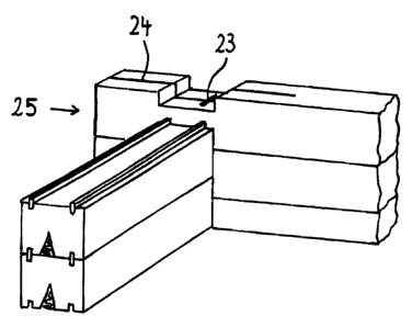
For the corner halving, shown in Figs. 8 and 9, of
outside walls of a block plank house, a tightening tongue 23
vertically penetrating the block plank is inserted into the
block planks in the region of the corner halving,
transversely to the longitudinal direction of the block
plank. From its outward-pointing face end 25, the block
plank has a spline 24, which is oriented toward the
tightening tongue 23 and into which a wedge 26 that can be
driven farther in is inserted at the face end of the plank.
When shrinkage occurs, the wedge can be driven farther in,
and the corner halving can be further tightened and made
windproof. For reasons of appearance, the wedge 26 can be
covered by a removable cover plate.
The block planks for the corner halving of outside
walls of a block plank house can each have a vertical,
spreadable longitudinal slit, preferably embodied as a spline
6
CA 02434310 2003-07-22
24, extending from their outward-pointing face end to beyond
the region of the corner halving. What is important is the
possibility of driving the block planks apart in order to
compensate for the attendant shrinkage, and driving the block
planks to the size sawn out in the region of the corner
halving and to seal them off from one another.
7