Sélection de la langue

Search

Sommaire du brevet 2435441 

Énoncé de désistement de responsabilité concernant l'information provenant de tiers

Une partie des informations de ce site Web a été fournie par des sources externes. Le gouvernement du Canada n'assume aucune responsabilité concernant la précision, l'actualité ou la fiabilité des informations fournies par les sources externes. Les utilisateurs qui désirent employer cette information devraient consulter directement la source des informations. Le contenu fourni par les sources externes n'est pas assujetti aux exigences sur les langues officielles, la protection des renseignements personnels et l'accessibilité.

Disponibilité de l'Abrégé et des Revendications

L'apparition de différences dans le texte et l'image des Revendications et de l'Abrégé dépend du moment auquel le document est publié. Les textes des Revendications et de l'Abrégé sont affichés :

  • lorsque la demande peut être examinée par le public;
  • lorsque le brevet est émis (délivrance).
(12) Brevet: (11) CA 2435441
(54) Titre français: RAMASSEUSE DE TRAVERSES D'UNE VOIE
(54) Titre anglais: A MACHINE FOR PICKING UP SLEEPERS OF A TRACK
Statut: Réputé périmé
Données bibliographiques
(51) Classification internationale des brevets (CIB):
  • E01B 29/06 (2006.01)
  • E01B 29/09 (2006.01)
(72) Inventeurs :
  • THEURER, JOSEF (Autriche)
  • BRUNNINGER, MANFRED (Autriche)
(73) Titulaires :
  • FRANZ PLASSER BAHNBAUMASCHINEN-INDUSTRIEGESELLSCHAFT M.B.H. (Autriche)
(71) Demandeurs :
  • FRANZ PLASSER BAHNBAUMASCHINEN-INDUSTRIEGESELLSCHAFT M.B.H. (Autriche)
(74) Agent: RICHES, MCKENZIE & HERBERT LLP
(74) Co-agent:
(45) Délivré: 2006-12-05
(22) Date de dépôt: 2003-07-16
(41) Mise à la disponibilité du public: 2004-01-17
Requête d'examen: 2003-07-16
Licence disponible: S.O.
(25) Langue des documents déposés: Anglais

Traité de coopération en matière de brevets (PCT): Non

(30) Données de priorité de la demande:
Numéro de la demande Pays / territoire Date
GM475/2002 Autriche 2002-07-17

Abrégés

Abrégé français

Machine (5) de ramassage des traverses (2) d'une voie ferrée (3) équipée d'un dispositif de ramassage de traverses (1) comprenant une chaîne de transport sans fin (12). La chaîne de transport est disposée de manière inclinée par rapport à une ligne de référence (30) définie par les extrémités de renvoi (10, 11) d'un angle alpha<90 degrés par rapport au lit de ballast dans laquelle l'extrémité de renvoi inférieure (11) étant positionnée avant l'extrémité de renvoi supérieure (10), par rapport à la direction de travail (10). Des patins de traverses (15) sont réalisés de manière prolongée par une glissière de traverse (16) s'étendant dans une direction longitudinale de la machine pour un appui des traverses (2) sur une face inférieure de traverse (25) afin de transporter les traverses sur une unité de transport de traverse (18).


Abrégé anglais

A machine (5) for picking up sleepers (2) of a track (3) is equipped with a sleeper pick-up device (1) comprising an endless transporting chain (12). The fatter is arranged, with respect to a reference line (30) defined by deflection ends (10,11), inclined to the ballast bed (14) at an angle .alpha. < 90°, wherein - with regard to a working direction (8) - the lower deflection end (11) is positioned ahead of the upper deflection end (10). Sleeper skids (15) are designed extended by means of a sleeper sliding track (16) - for supporting the sleepers (2) on a sleeper underside (25) - running in a longitudinal direction of the machine, in order to transport the sleepers (2) onto a sleeper transport unit (18).

Revendications

Note : Les revendications sont présentées dans la langue officielle dans laquelle elles ont été soumises.


4
Claim
A machine (5) for picking up sleepers (2) of a track (3) while advancing con-
tinuously in a working direction (8), including a sleeper pick-up device (1)
comprising an endless transporting chain (12) provided for shifting the sleep-
ers (2) from a ballast bed (14) to a receiving end (17) of a sleeper transport
unit (18), the transporting chain (12) having engaging members (9) and an
upper and a lower deflection end (10,11), and sleeper skids (15) provided for
permanent immersion into the ballast bed (14) for supporting the sleeper (2)
to be lifted, whereby the transporting chain (12), with respect to a reference
line (30) defined by both deflection ends (10,11), is arranged inclined to the
ballast bed (14) at an angle .alpha. < 90°, wherein the lower
deflection end (11) is
positioned ahead of the upper deflection end (10) with regard to the working
direction (8), and that the sleeper skids (15) - for supporting the sleepers
(2)
on a sleeper underside (25) - are designed extended by means of a sleeper
sliding track (16), running in a longitudinal direction of the machine
characterized by the following features:
a) the sleeper skids (15) have a transfer end (19) located in the region of
the receiving end (17) of the sleeper transport unit (18),
b) a sleeper pusher (20) is provided in the region of the lower deflection end
(11) and above the sleeper skids (15), the sleeper pusher (20) being pivotable
by means of a drive (21) about an axis (23), extending perpendicularly to the
longitudinal direction of the machine, and being longitudinally displaceable
by
means of a further drive (22) in the longitudinal direction of the machine and
relative to the lower deflection end (11).

Description

Note : Les descriptions sont présentées dans la langue officielle dans laquelle elles ont été soumises.

CA 02435441 2006-O1-18
1
A Machine for Picking Up Sleepers of a Track
The invention relates to a machine for picking up sleepers of a track while ad-

vancing continuously in a working direction, including a sleeper pick-up de-
vice comprising an endless transporting chain provided for shifting the sleep-
ers from a ballast bed to a receiving end of a sleeper transport unit, the
trans-
porting chain having engaging members and an upper and a lower deflection
end, and sleeper skids provided for permanent immersion into the ballast bed
for supporting the sleeper to be lifted, whereby the transporting chain, with
respect to a reference line defined by both deflection ends, is arranged in-
clined to the ballast bed at an angle < 90°, wherein the lower
deflection end is
positioned ahead of the upper deflection end with regard to the working direc-
tion, and that the sleeper skids - for supporting the sleepers on a sleeper un-

derside - are designed extended by means of a sleeper sliding track, running
in a longitudinal direction of the machine.
A machine of this type is known, for instance, from US 5 357 867. The old
sleepers which are to be removed in the course of a track renewal operation
are lifted off the ballast bed by the sleeper pick-up device and
intermediately
stored on the machine. The sleeper, initially seized by the sleeper skids, is
collected by means of a pivotable and vertically adjustable fork, lifted and
de-
posited, with the sleeper underside down, upon an engaging member of the
endless transporting chain. The latter finally transports the sleeper to the
higher positioned sleeper transport unit.
The object of the present invention is to create a machine of the specified
kind with which a more efficient sleeper pick-up operation is possible.
According to the invention, this object is achieved with a machine of the kind
mentioned at the beginning which is characterized by following features:
a) the sleeper skids have a transfer end located in the region of the receiv-
ing end of the sleeper transport unit,

CA 02435441 2006-O1-18
la
b) a sleeper pusher is provided in the region of the lower deflection end and
above the sleeper skids, the sleeper pusher being pivotable by means of a
drive about an axis, extending perpendicularly to the longitudinal direction
of
the machine, and being longitudinally displaceable by means of a further drive
in the longitudinal direction of the machine and relative to the lower
deflection
end.
A solution like this has the advantage that the old sleeper to be removed is
displaced slidingly, starting from the sleeper skids to the upper end of the
sleeper pick-up device, thus rendering superfluous an efficiency-limiting
trans-
fer cycle of a single sleeper, such as described at the beginning. This struc-
tural solution provides a buffering possibility in the region of the sleeper
skids
on which, if necessary, even two immediately adjacent sleepers can be seized
by the engaging member and displaced vertically without problems. Thus, in a
particularly advantageous manner, even the presence of double sleepers at a
rail joint does not cause a reduction of the working performance of the ma-
chine.

CA 02435441 2006-O1-18
2
Additional advantages and features of the invention become apparent from
the drawing.
The invention will be described in more detail below with reference to an
embodiment represented in the drawing.
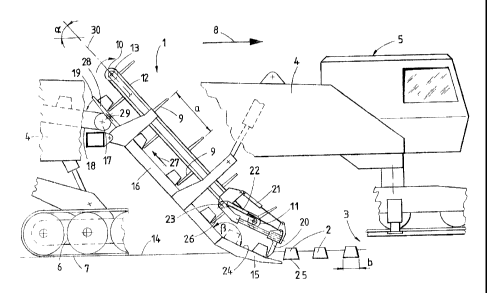
A sleeper pick-up device 1, shown in the drawing in side view, for picking up
sleepers 2 of a track 3 is connected to a machine frame 4 of a machine 5
provided for track renewal. The machine 5 is mobile in a working direction 8
by means of a caterpillar-tracked undercarriage 7 having a motive drive 6.
The sleeper pick-up device 1 consists of an endless transporting chain 12,
connected to engaging members 9 and comprising an upper and a lower
deflection end 10,11, with which is associated a rotation drive 13. With
respect to a reference line 30 defined by the deflection ends 10,11, the
transporting chain 12 is arranged inclined to a ballast bed 14 at an angle a
which is less than 90°, with the lower deflection end 11 being
positioned
ahead of the upper deflection end 10 in the working direction 8. A distance a
between two adjacent engaging members 9 amounts to at least twice a
sleeper width b.
Located underneath the lower deflection end 11 are two sleeper skids 15,
spaced from one another in the longitudinal direction of the sleepers, which
are extended by means of a sleeper sliding track 16 running in the
longitudinal direction of the machine and parallel to the transporting chain
12.
The sleeper sliding track 16 comprises a transfer end 19 positioned in the
region of a receiving end 17 of a sleeper transport unit 18.
In the region of the lower deflection end 11 and above the sleeper skids 15, a
sleeper pusher 20 is provided which is pivotable about an axis 23 and
displaceable in the longitudinal direction of the machine by means of drives
21,22. The axis 23 extends perpendicularly to the longitudinal direction of
the
machine and horizontally. An angle ~, enclosed by the sleeper sliding track 16

CA 02435441 2003-07-16
and a skid sliding surface 24 of the sleeper skids 15, lies preferably within
a
range of 130° to 160°.
in working operations, in a continuous advance movement of the machine 5,
the sleeper skids 15 are shoved under a sleeper tanderside 25 of the sleeper 2
to be removed. Parallel thereto, the sleeper pusher 20 is raised by means of
the drives 21,22; pushed forward and Powered immediately in front of the
preceding sleeper 2 (position represented in solid lines). Subsequently, the
sleeper pusher 20 together with the sleeper 2 is pushed back in the direction
towards the sleeper sliding track 16 (see dash-dotted sleeper). In the
meantime, a rotation of the transporting chain 12 causes engaging members 9
to be applied to a forward-facing sleeper side surface 26 and to thus push the
sleeper 2 along the sleeper sliding track 16 in a direction indicated by an
arrow 27. This cycle for picking-up sleepers is repeated uvith the machine 5
advancing continuously, while parallei thereto, by permanent rotation of the
transporting chain 12, the sleepers 2 located on the sleeper sliding track 16
are transported in the direction towards the receiving end 17. As soon as the
latter is reached, a deflection flap 28 is pivoted about an axis 29 extending
perpendicularly to the longitudinal direction of the machine, and the steeper
2
is thus transported onto the receiving end 17.
A particular advantage of this steeper pick-up device 1 lies in the fact that,
if
the machine 5 is moving at correspondingly quick speed, a second sleeper 2
can be pushed onto the skid sliding surface 24 without problems, and both
sleepers 2 can be transported upwards by means of one engaging member 9.

Dessin représentatif
Une figure unique qui représente un dessin illustrant l'invention.
États administratifs

Pour une meilleure compréhension de l'état de la demande ou brevet qui figure sur cette page, la rubrique Mise en garde , et les descriptions de Brevet , États administratifs , Taxes périodiques et Historique des paiements devraient être consultées.

États administratifs

Titre Date
Date de délivrance prévu 2006-12-05
(22) Dépôt 2003-07-16
Requête d'examen 2003-07-16
(41) Mise à la disponibilité du public 2004-01-17
(45) Délivré 2006-12-05
Réputé périmé 2019-07-16

Historique d'abandonnement

Il n'y a pas d'historique d'abandonnement

Historique des paiements

Type de taxes Anniversaire Échéance Montant payé Date payée
Requête d'examen 400,00 $ 2003-07-16
Enregistrement de documents 100,00 $ 2003-07-16
Le dépôt d'une demande de brevet 300,00 $ 2003-07-16
Taxe de maintien en état - Demande - nouvelle loi 2 2005-07-18 100,00 $ 2005-06-16
Taxe de maintien en état - Demande - nouvelle loi 3 2006-07-17 100,00 $ 2006-06-21
Taxe finale 300,00 $ 2006-09-19
Taxe de maintien en état - brevet - nouvelle loi 4 2007-07-16 100,00 $ 2007-06-22
Taxe de maintien en état - brevet - nouvelle loi 5 2008-07-16 200,00 $ 2008-06-25
Taxe de maintien en état - brevet - nouvelle loi 6 2009-07-16 200,00 $ 2009-06-25
Taxe de maintien en état - brevet - nouvelle loi 7 2010-07-16 200,00 $ 2010-06-25
Taxe de maintien en état - brevet - nouvelle loi 8 2011-07-18 200,00 $ 2011-06-27
Taxe de maintien en état - brevet - nouvelle loi 9 2012-07-16 200,00 $ 2012-06-27
Taxe de maintien en état - brevet - nouvelle loi 10 2013-07-16 250,00 $ 2013-06-27
Taxe de maintien en état - brevet - nouvelle loi 11 2014-07-16 250,00 $ 2014-06-23
Taxe de maintien en état - brevet - nouvelle loi 12 2015-07-16 250,00 $ 2015-06-22
Taxe de maintien en état - brevet - nouvelle loi 13 2016-07-18 250,00 $ 2016-06-13
Taxe de maintien en état - brevet - nouvelle loi 14 2017-07-17 250,00 $ 2017-06-14
Titulaires au dossier

Les titulaires actuels et antérieures au dossier sont affichés en ordre alphabétique.

Titulaires actuels au dossier
FRANZ PLASSER BAHNBAUMASCHINEN-INDUSTRIEGESELLSCHAFT M.B.H.
Titulaires antérieures au dossier
BRUNNINGER, MANFRED
THEURER, JOSEF
Les propriétaires antérieurs qui ne figurent pas dans la liste des « Propriétaires au dossier » apparaîtront dans d'autres documents au dossier.
Documents

Pour visionner les fichiers sélectionnés, entrer le code reCAPTCHA :


Pour visualiser une image, cliquer sur un lien dans la colonne description du document. Pour télécharger l'image (les images), cliquer l'une ou plusieurs cases à cocher dans la première colonne et ensuite cliquer sur le bouton "Télécharger sélection en format PDF (archive Zip)" ou le bouton "Télécharger sélection (en un fichier PDF fusionné)".

Liste des documents de brevet publiés et non publiés sur la BDBC .

Si vous avez des difficultés à accéder au contenu, veuillez communiquer avec le Centre de services à la clientèle au 1-866-997-1936, ou envoyer un courriel au Centre de service à la clientèle de l'OPIC.


Description du
Document 
Date
(yyyy-mm-dd) 
Nombre de pages   Taille de l'image (Ko) 
Description 2006-01-18 4 172
Revendications 2006-01-18 1 40
Abrégé 2003-07-16 1 24
Description 2003-07-16 3 159
Revendications 2003-07-16 2 84
Dessins 2003-07-16 1 31
Dessins représentatifs 2003-09-22 1 20
Page couverture 2003-12-22 1 49
Dessins représentatifs 2006-11-09 1 20
Page couverture 2006-11-09 1 50
Correspondance 2006-09-19 1 46
Cession 2003-07-16 4 194
Taxes 2005-06-16 1 34
Poursuite-Amendment 2005-09-01 2 64
Poursuite-Amendment 2006-01-18 7 231
Taxes 2006-06-21 1 44