Sélection de la langue

Search

Sommaire du brevet 2437448 

Énoncé de désistement de responsabilité concernant l'information provenant de tiers

Une partie des informations de ce site Web a été fournie par des sources externes. Le gouvernement du Canada n'assume aucune responsabilité concernant la précision, l'actualité ou la fiabilité des informations fournies par les sources externes. Les utilisateurs qui désirent employer cette information devraient consulter directement la source des informations. Le contenu fourni par les sources externes n'est pas assujetti aux exigences sur les langues officielles, la protection des renseignements personnels et l'accessibilité.

Disponibilité de l'Abrégé et des Revendications

L'apparition de différences dans le texte et l'image des Revendications et de l'Abrégé dépend du moment auquel le document est publié. Les textes des Revendications et de l'Abrégé sont affichés :

  • lorsque la demande peut être examinée par le public;
  • lorsque le brevet est émis (délivrance).
(12) Brevet: (11) CA 2437448
(54) Titre français: TROP-PLEIN POUR BAIGNOIRES ET APPAREILS SANITAIRES SEMBLABLES
(54) Titre anglais: OVERFLOW ASSEMBLY FOR BATHTUBS AND THE LIKE
Statut: Périmé
Données bibliographiques
(51) Classification internationale des brevets (CIB):
  • E03C 1/24 (2006.01)
(72) Inventeurs :
  • BALL, WILLIAM T. (Etats-Unis d'Amérique)
(73) Titulaires :
  • WCM INDUSTRIES, INC. (Etats-Unis d'Amérique)
(71) Demandeurs :
  • WCM INDUSTRIES, INC. (Etats-Unis d'Amérique)
(74) Agent: SMART & BIGGAR LP
(74) Co-agent:
(45) Délivré: 2007-11-06
(22) Date de dépôt: 2003-08-18
(41) Mise à la disponibilité du public: 2004-02-16
Requête d'examen: 2003-08-18
Licence disponible: S.O.
(25) Langue des documents déposés: Anglais

Traité de coopération en matière de brevets (PCT): Non

(30) Données de priorité de la demande:
Numéro de la demande Pays / territoire Date
10/222,062 Etats-Unis d'Amérique 2002-08-16

Abrégés

Abrégé français

Un raccord de trop-plein monopièce est présenté pour une baignoire dotée d'un tuyau de trop-plein monopièce. Le tuyau de trop-plein monopièce est de forme en L inversé comportant une portion de coude définissant une portion d'extrémité supérieure et une portion d'extrémité inférieure. La portion d'extrémité supérieure comporte une extrémité extérieure définissant une entrée adaptée pour convenir à un orifice de trop-plein de baignoire. Les filets sont situés sur une surface extérieure de la portion d'extrémité supérieure et entourent l'entrée. Une lèvre s'étend radialement vers l'extérieur à partir d'une surface extérieure du tuyau de trop-plein entre la portion de coude et la portion d'extrémité supérieure pour engager une surface extérieure de la paroi d'extrémité de la baignoire autour de l'orifice du trop-plein de la baignoire. Un mince diaphragme est scellé à l'extrémité extérieure de la portion d'extrémité supérieure pour fermer l'entrée à l'écoulement du fluide.


Abrégé anglais

A one-piece overflow fitting is provided for a bathtub having a one piece overflow pipe. The one piece overflow pipe has an inverted L-shape having an elbow portion defining an upper end portion and a lower end portion. The upper end portion has an outer end defining an inlet adapted to fit through a bathtub overflow port. Threads are located on an outer surface of the upper end portion and surround the inlet. A lip extends radially outwardly from an outer surface of the overflow pipe between the elbow portion and the upper end portion to engage an outer surface of the bathtub end wall around the bathtub overflow port. A thin diaphragm is sealed to the outer end of the upper end portion to close the inlet to fluid flow.

Revendications

Note : Les revendications sont présentées dans la langue officielle dans laquelle elles ont été soumises.


Claims:

1. A one-piece overflow fitting for a bathtub which has a bottom
and adjacent side and end walls, and an overflow port in an end wall,
comprising:
a one-piece overflow fitting comprising:
an overflow pipe with an inverted L-shape having an
elbow portion defining an upper end portion and a lower end
portion, the upper end portion having an outer end defining an
inlet being adapted to fit through the bathtub overflow port;
threads on an outer surface of the upper end portion and
surrounding the inlet and normally extending through the
bathtub overflow port;
a lip extending radially outwardly from an outer surface
of the overflow pipe between the elbow portion and the upper
end portion and being spaced from the inlet to engage an outer
surface of the bathtub end wall around the bathtub overflow
port; and
a thin diaphragm sealed to the outer end of the upper
end portion to close the inlet to fluid flow;
a nut element compatible with the threads wherein the nut
element has a threaded portion for threadibly mounting the nut to the
upper end portion to clamp the overflow fitting to the end of the bathtub
between the lip and the nut element, and at least one lug extending
radially from the nut; and
a cap detachably encased to the lug, covering the nut and
adapted to contact the bathtub end wall.


2. The one-piece overflow fitting of claim 1, wherein the diaphragm
is of plastic material.


3. The one-piece overflow fitting of claim 1, wherein the diaphragm
is integral with the outer end and is held to the outer end only through
having been integrally formed therewith.


4. A one-piece overflow assembly fitting for a bathtub which has a
bottom and adjacent side end walls, and an overflow port in an end
wall, comprising:
an overflow pipe with an inverted L-shape having a lip on an
outer surface, an elbow portion defining an upper end portion and a
lower end portion, the upper end portion having threads on the outer
surface and an outer end defining an inlet to the end portion of the
overflow pipe being adapted to fit through the bathtub overflow port;
threads on an outer surface of the upper end portion and
surrounding the inlet and normally extending through the bathtub
overflow port;
a lip extending radially outwardly from an outer surface of the
overflow pipe between the elbow portion and the upper end portion
and being spaced from the inlet to engage an outer surface of the
bathtub end wall around the bathtub overflow port;
a thin diaphragm sealed to the outer end of the upper end
portion to close the inlet to fluid flow; and wherein the diaphragm is a
circular membrane and has a diameter that is not less than the
diameter of the outer end of the overflow pipe.


5. The one-piece overflow fitting of claim 1, wherein the diaphragm
is hermetically sealed to the outer end.


6. The one-piece overflow fitting of claim 1, wherein the one-piece
overflow fitting is adapted to be installed in the end wall of a bathtub
without solvent cement.


7. The assembly of claim 1, wherein the nut is a slip nut.


Description

Note : Les descriptions sont présentées dans la langue officielle dans laquelle elles ont été soumises.


CA 02437448 2003-08-18
TITLE: OVERFLOW ASSEMBLY FOR BATHTUBS AND THE LIKE
BACKGROUND OF THE INVENTION
In new building construction, the plumbers prefer
not to put the finished closure valves in the bottom of
tubs, or the finished decarative plate over the overflow
outlet at the end of the tub until the project is
finished. The plumbers prefer this because these
elements will often be damaged as the construction
project is brought to a close. Further, the piping for
both of the outlets needs to be checked far leaks before
the inspection process is completed. This test involves
running water down a vent attached to the drain until the
water reaches a level above the tub. The tester then
determines whether any of the piping leaks. Thus, when
the testing operation is to take place, a plug is put in
the bottom drain of the tub and some sort of seal plate
is placed at the end of the tub on the overflow outlet.
Existing overflow plates have a center opening
therein. There are either two or four small screw hales
in the plate adjacent to the center opening. These screw
holes are used to hold the plate to the plumbing fixture.
The testing procedure usually involves stuffing a balloon
through the large center opening into the pipe in the
wall. The pipe is sealed when the balloon is inflated.
Further, existing seal plates normally have to be removed
when the decorative plate is put on.
It is therefore an abject of this inveni~ion to
provide an overflow fitting which will safeguard the
overflow system during construction.
A further object of the invention is to provide an
overflow fitting which will prepare the overflow system
for testing.
1

CA 02437448 2003-08-18
A still further object of the invention is to
provide an overflow fitting which allows a user to
install the overflow fitting without using solvent
cement.
These and other objects will be apparent to those
skilled in the art.
SUMMARY OF THE INVENTION
A one-piece overflow fitting is provided for a
bathtub having a one piece overflow pipe. The one piece
overflow pipe has an inverted L-shape having an elbow
portion defining an upper end portion and a lower end
portion. The upper end portion has an outer end defining
an inlet adapted to fit through a bathtub overflow port.
Threads are located on an outer surface of the upper end
portion and surround the inlet. A lip extends radiall~r
outwardly from an outer surface of the overflow pipe
between the elbow portion and the upper end portion to
engage an outer surface of the bathtub end wall around
the bathtub overflow port. A thin diaphragm is sealed to
the outer end of the upper end portion to close the inlet
to fluid flow.
DESCRIPTION OF THE DRAWINGS
Fig. 1 is a sectional side view of a conventional
bathtub environment utilizing the device of this
invention;
Fig. 2 is a side view of the device of this
invention;
Fig. 3 is a front view of the device of this
invention;
Fig. 4 is an exploded perspective view of the device
of this invention; and
2

CA 02437448 2003-08-18
Fig. 5 is a perspective view of the installation of
the device of this invention.
DESCRIPTION OF THE PREFERRED EMBODIMENT
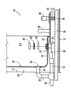
S With reference to Fig. 1, a conventional bathroom
structure 10 has a floor 12, and a hollow wall 14 with a
wall opening 16 therein. A conventional bathtub
(hereinafter "tub") 20 rests upon floor 12.
The tub 20 has side walls 22, end walls 24, and a
bottom 26. The side walls 22 extend upwardly from the
bottom 26. The end walls 24 extend upwardly from the
bottom 26, perpendicular to the side walls 22, and have
an outer surface 25.
A drain port 28 is located in the boti:om 26. A
conventional overflow port 30 is located in the end wall
24. A first vertical drain pipe 32 extends downwardly
from drain port 28. A second vertical drain pipe 34
extends downwardly from the overflow port 30. A
horizontal pipe 36 connects pipes 32 and 34. A primary
drain pipe 38 extends downwardly from the function of
pipes 34 and 36.
A conventional vertical vent pipe 40 is located
within the hollow wall 14. A connector vent pipe 42 is
in fluid flow communication with the vent pipe 40 and the
upper end of the second vertical drain pipe 34.
Conventional water pipes 44 extend through hollow
wall 14 and are connected to a valve 46. The valve 46 is
interconnected with conventional control members 48 and
faucet 50. A one-piece overflow fitting 60 is attached
to the second vertical drain pipe 34, and a portion of
the overflow fitting 60 passes through overflow port 30.
With reference to Figs. 2-4, the overflow fitting 60
has an overflow pipe 62 with an inverted L-s~.iape. The
overflow pipe 62 has an elbow portion 65 which defines an
3

CA 02437448 2003-08-18
upper end portion 66 and a lower end portion 67. It will
be understood that the overflow pipe 62 may be made of
copper, plastic, or any other suitable material.
The upper end portion 66 has threads 68 on its outer
surface and also has an outer end 70. The outer end 70
defines an inlet 71 to the upper end portion 66 of the
overflow pipe 62. The inlet 71 is adapted to fit through
the bathtub overflow port 30.
The overflow fitting 60 also has a lip 74 extending
radially outwardly from an outer surface of the overflow
pipe 62 between the elbow portion 65 and the upper end
portion 66. The lip 74 is spaced from the inlet 71 to
engage an outer surface 25 of the bathtub end wall 24
around the bathtub overflow port 30, thereby allowing
only the upper end portion 66 to pass through the
overflow port 30.
A thin diaphragm 80 is sealed to the outer end 70 of
the end portion 66. The diaphragm 80 is a Circular
membrane and has a diameter that is not less than tree
diameter of the outer end 70 of the overflow pipe 62. In
one embodiment, the diaphragm 80 is integral with the
outer end 70 and is held to the outer end 70 only through
having been integrally formed therewith. The diaphragm 80
may be hermetically sealed to the outer end 70. The
diaphragm 80 may be composed of plastic material,
flexible rubber, or the like. The diaphragm 80 is
composed of a material that is easily punctured or easily
removable.
Referring to Figs. 1 and 4, the overflow pipe
fitting 60 further includes, a nut element 90 having
threads compatible with the threads 68 on the upper end
portion 66 of the overflow pipe 62. The nut element 90
removably secures the overflow pipe 62 to the bathtub 20
4

CA 02437448 2003-08-18
by compressing the end wall 24 between the nut element 90
and the lip 74. The nut element 90 may be a slip nut.
As shown in Fig. 4, the nut element 90 has a series
of radially extending lugs 92 along the nut 90 outer
periphery. These lugs 92 detachably engage the inner
surface of a cap 96. The cap 96 serves to cover the
overflow pipe fitting 60 hardware.
During installation of the overflow pipe fitting 60,
a washer 94 may be placed between the upper end portion
66 of the overflow pipe 62 and the nut element 90. The
washer 94 seals the overflow pipe fitting 60 to the tub
20.
In operation, the drainage system of i~he ports 28
and 30; pipes 32, 34, 36, 38; and the overflow pipe
fitting 60 are installed as shown in Fig. 1. Vertical
vent pipe 40 and connector vent pipe 42 are also
installed.
In the testing procedure, the port 28 is plugged in
any conventional manner. The overflow pipe fitting 60 is
attached to the second vertical drain pipe 34 already
plugged by the diaphragm 80 as described above, so there
is no fluid access to the upper end of pipe 34 either
inwardly or outwardly out of the overflow port 30. The
vertical vent pipe 40 is charged with water at some
elevation above pipe 42 so that it can be determined if
there are any leaks in the system.
With reference to Fig. 5, having determined that
there are no leaks, the water is purged from the system.
The plumber can then approach overflow port 30, and by
using a cutting device 100, such as a knife of any other
sharp object, cuts 102 can be made in the diaphragm 80.
This can be quickly and easily done without disassembla_ng
any of the structure of overflow pipe fitting 60. Any
valve linkage elements required may be installed through
5

CA 02437448 2003-08-18
cuts 102, and any cap or cover for the overflow port 30
may be placed over the overflow pipe 62 end portion 66.
It is therefore seen that this invention eliminates
any need to seal shut the overflow pipe 62 after the pipe
S 62 has been attached to the second vertical drain pipe
34. The invention also eliminates any need to :remove
sealing components from the overflow port 30 after the
testing procedure has taken place. In addition, the
invention allows a user to install the overflow fitting
60 without using solvent cement.
It is therefore seen that this invention will
accomplish at least all of its stated objectives.
6

Dessin représentatif
Une figure unique qui représente un dessin illustrant l'invention.
États administratifs

Pour une meilleure compréhension de l'état de la demande ou brevet qui figure sur cette page, la rubrique Mise en garde , et les descriptions de Brevet , États administratifs , Taxes périodiques et Historique des paiements devraient être consultées.

États administratifs

Titre Date
Date de délivrance prévu 2007-11-06
(22) Dépôt 2003-08-18
Requête d'examen 2003-08-18
(41) Mise à la disponibilité du public 2004-02-16
(45) Délivré 2007-11-06
Expiré 2023-08-18

Historique d'abandonnement

Il n'y a pas d'historique d'abandonnement

Historique des paiements

Type de taxes Anniversaire Échéance Montant payé Date payée
Requête d'examen 400,00 $ 2003-08-18
Enregistrement de documents 100,00 $ 2003-08-18
Le dépôt d'une demande de brevet 300,00 $ 2003-08-18
Taxe de maintien en état - Demande - nouvelle loi 2 2005-08-18 100,00 $ 2005-07-15
Taxe de maintien en état - Demande - nouvelle loi 3 2006-08-18 100,00 $ 2006-07-14
Taxe finale 300,00 $ 2007-05-24
Taxe de maintien en état - Demande - nouvelle loi 4 2007-08-20 100,00 $ 2007-08-20
Taxe de maintien en état - brevet - nouvelle loi 5 2008-08-18 200,00 $ 2008-07-31
Taxe de maintien en état - brevet - nouvelle loi 6 2009-08-18 200,00 $ 2009-08-04
Taxe de maintien en état - brevet - nouvelle loi 7 2010-08-18 200,00 $ 2010-07-30
Taxe de maintien en état - brevet - nouvelle loi 8 2011-08-18 200,00 $ 2011-08-01
Taxe de maintien en état - brevet - nouvelle loi 9 2012-08-20 200,00 $ 2012-07-30
Taxe de maintien en état - brevet - nouvelle loi 10 2013-08-19 250,00 $ 2013-08-14
Taxe de maintien en état - brevet - nouvelle loi 11 2014-08-18 250,00 $ 2014-08-06
Taxe de maintien en état - brevet - nouvelle loi 12 2015-08-18 250,00 $ 2015-08-17
Taxe de maintien en état - brevet - nouvelle loi 13 2016-08-18 250,00 $ 2016-08-17
Taxe de maintien en état - brevet - nouvelle loi 14 2017-08-18 250,00 $ 2017-08-02
Taxe de maintien en état - brevet - nouvelle loi 15 2018-08-20 450,00 $ 2018-07-25
Taxe de maintien en état - brevet - nouvelle loi 16 2019-08-19 450,00 $ 2019-07-24
Taxe de maintien en état - brevet - nouvelle loi 17 2020-08-18 450,00 $ 2020-07-29
Taxe de maintien en état - brevet - nouvelle loi 18 2021-08-18 459,00 $ 2021-07-28
Taxe de maintien en état - brevet - nouvelle loi 19 2022-08-18 458,08 $ 2022-06-29
Titulaires au dossier

Les titulaires actuels et antérieures au dossier sont affichés en ordre alphabétique.

Titulaires actuels au dossier
WCM INDUSTRIES, INC.
Titulaires antérieures au dossier
BALL, WILLIAM T.
Les propriétaires antérieurs qui ne figurent pas dans la liste des « Propriétaires au dossier » apparaîtront dans d'autres documents au dossier.
Documents

Pour visionner les fichiers sélectionnés, entrer le code reCAPTCHA :


Pour visualiser une image, cliquer sur un lien dans la colonne description du document. Pour télécharger l'image (les images), cliquer l'une ou plusieurs cases à cocher dans la première colonne et ensuite cliquer sur le bouton "Télécharger sélection en format PDF (archive Zip)" ou le bouton "Télécharger sélection (en un fichier PDF fusionné)".

Liste des documents de brevet publiés et non publiés sur la BDBC .

Si vous avez des difficultés à accéder au contenu, veuillez communiquer avec le Centre de services à la clientèle au 1-866-997-1936, ou envoyer un courriel au Centre de service à la clientèle de l'OPIC.


Description du
Document 
Date
(yyyy-mm-dd) 
Nombre de pages   Taille de l'image (Ko) 
Abrégé 2003-08-18 1 25
Description 2003-08-18 6 280
Revendications 2003-08-18 2 59
Dessins 2003-08-18 4 78
Dessins représentatifs 2003-10-10 1 10
Page couverture 2004-01-23 1 39
Revendications 2007-02-14 2 66
Page couverture 2007-10-11 2 43
Cession 2003-08-18 9 435
Poursuite-Amendment 2003-11-07 1 37
Taxes 2005-07-15 1 27
Taxes 2006-07-14 1 28
Poursuite-Amendment 2006-08-15 2 77
Poursuite-Amendment 2007-02-14 5 135
Correspondance 2007-05-24 1 26
Taxes 2007-08-20 1 29