Note : Les descriptions sont présentées dans la langue officielle dans laquelle elles ont été soumises.
CA 02442662 2003-09-29
WO 02/078790 PCT/GB02/01476
TITLE OF THE INVENTION
Fire and Explosion Suppression
BACKGROUND OF THE INVENTION
1. Field of the Invention
The invention relates to fire and explosion suppression. Embodiments of the
invention, to
be described below by way of example only, use liquid suppressants in mist
form. The
suppressants used are intended to deal with the problems of ozone depletion
and global
warming.
2. Description of the Related Art
It is known (e.g. from GB-A-2 265 309) to extinguish fires or explosions by
discharging a
liquid chemical fire extinguishing substance in mist form in suspension in an
inert gas.
It is also known from WO-A-015468 to discharge a chemical fire extinguishing
substance
in liquid form by means of an inert gas.
CA 02442662 2009-04-28
2
BRIEF SUMMARY OF THE INVENTION
According to the invention, there is provided a method of suppressing a fire
or
explosion, in which a fire or explosion suppressing chemical substance which
is in
liquid form or substantially so at normal temperatures and pressures is
dispersed as a
suspension in a fire or explosion suppressing inert gas and discharged with
the gas into
an area to be protected, the method comprising the steps of:
producing a mist of the chemical substance and entraining the mist in the gas,
the
production of the mist and the entrainment of the mist in the gas taking place
before the
discharge of the suspension into the area to be protected; and
discharging the suspension into the area to be protected, the chemical
substance when
so dispersed having low environmental impact, with a short atmospheric
lifetime of
less than 30 days; the chemical substance comprising one or more chemicals
with the
structure Z-R-X-Y, where the monovalent radical Z is a halogen atom taken from
the
group fluorine (-F) or bromine (-Br); where the divalent radical R is a
perfluoro- or
polyfluoro-alkylidene group of formula -CõHpF2i_P - with n in the range 1-6
and p in the
range 0-4; where the divalent radical X is either an ether linkage (-O-) or an
alkenic
linkage of the formula -CW=CH- with W being either H or Br; and where the
monovalent radical Y is selected from the group hydrogen (-H), bromine (-Br),
alkyi of
formula -CmH2nõ+i with m in the range 1-4, perfluoroalkyl of formula -
C,,,FZm+] with m
in the range 1-4, or polyfluoroalkyl of formula -C,,,HkF2,,,+l_k with m in the
range 1-4
and k in the range 1-2m; and with the provisos that (i) there is one, and only
one,
bromine atom in the chemical Z-R-X-Y, and that (ii) the total number of carbon
atoms
in the chemical Z-R-X-Y is in the range 3-6.
CA 02442662 2009-04-28
3
According to the invention, there is also provided a fire or explosion
suppressant
system, comprising:
a source of a fire or explosion suppressing chemical substance which is in
liquid form
or substantially so at normal temperatures and pressures;
a source of a pressurised fire or explosion suppressing inert gas, means for
dispersing
the chemical substance as a suspension in the pressurised gas;
a disperser for dispersing the chemical substance as a suspension in the
pressurised gas,
the disperser being adapted for producing a mist of the chemical substance and
entraining the mist in the gas, and a discharger for discharging the
suspension into an
area to be protected; and
discharge means for discharging the so-dispersed chemical substance and the
pressurised gas into an area to be protected;
the chemical substance being dispersed as a suspension in the inert gas, the
chemical
substance when so dispersed having low environmental impact, with a short
atmospheric lifetime of less than 30 days; the chemical substance comprising
one or
more chemicals with the structure Z-R-X-Y, where the monovalent radical Z is a
halogen atom taken from the group fluorine (-F) or bromine (-Br); where the
divalent
radical R is a perfluoro- or polyfluoro-alkylidene group of formula -CõHpF2õ_p
- with n
in the range 1-6 and p in the range 0-4; where the divalent radical X is
either an ether
linkage (-O-) or an alkenic linkage of the formula -CW=CH- with W being either
H or
Br; and where the monovalent radical Y is selected from the group hydrogen (-
H),
bromine (-Br), alkyl of formula -CmHZm+l with m in the range 1-4,
perfluoroalkyl of
formula -CmF2rri+i with m in the range 1-4, or polyfluoroalkyl of formula -
CmHkFZm+i_k
with m in the range 1-4 and k in the range 1-2m; and with the provisos that
(i) there is
one, and only one, bromine atom in the chemical Z-R-X-Y, and that (ii) the
total
number of carbon atoms in the chemical Z-R-X-Y is in the range 3-6.
CA 02442662 2009-04-28
4
BRIEF DESCR.IPTION OF THE DRAWINGS
Fire and explosion suppression systems and methods according to the invention,
employing mists, will now be described by way of example only, with reference
to the
accompanying diagrammatic drawings in which:
Figure 1 is a schematic diagram of one of the systems; and
CA 02442662 2003-09-29
WO 02/078790 PCT/GB02/01476
Figure 2 is a schematic diagram of another of the systems.
DETAILED DESCRIPTION OF EMBODIMENTS OF THE INVENTION
Halons (Halons 1301 and 1211) have been used in the past as fire and explosion
extinguishants and suppressants. Their physical and toxicological properties
and
extinguishing efficiency made them ideal for total flooding and streaming
applications.
They are efficient extinguishing agents because they contain bromine atoms
which
terminate the radical chain reactions that propagate combustion by catalytic
reactions.
These same bromine atoms are now known to catalytically remove ozone in the
stratosphere. Therefore, Halons have an ozone depletion potential (ODP) and
their
production was ceased at the end of 1993. Since then, many alternative fire
suppressants
have reached the market place. Currently, hydrofluorocarbons dominate the
industrial and
commercial markets. However, aerospace, military and specialised uses are
still
dependent upon recycled Halon for space and weight efficiency reasons; the
current
Halon replacement agents are not as efficient as Halons for fire
extinguishing.
Another factor that indicates the environmental impact of an extinguishing
agent is its
global warming potential (GWP). This parameter is related to the atmospheric
lifetime of
a molecule and is becoming increasingly important and will continue to do so
in the
future. This is especially true following the Kyoto Protocol and greenhouse
gas emission
targets. Hydrofluorocarbons have an ODP of zero but they have material
atmospheric
lifetimes. As a result, their use is likely to be subject to restriction in
the future.
CA 02442662 2003-09-29
WO 02/078790 PCT/GB02/01476
6
Extinguishing agents with short atmospheric lifetimes are desirable.
There are several basic mechanisms for the breakdown of organic molecules
released into
the atmosphere :-
1. Reaction with =OH radicals: this is the principal tropospheric degradation
mechanism
for most organic molecules. The most common reaction is that of hydrogen atom
abstraction.
X-H + =OH --> =X + H20 (slow)
-X --> -+ final products (fast)
The rate of the whole process is controlled by the rate of the first reaction,
the hydrogen
abstraction reaction. The radical =X then breaks down very rapidly to the
final products
such as COZ, H2O, HF, HBr etc. which are washed out of the atmosphere in rain.
Clearly
the molecule must possess an abstractable hydrogen atom for this reaction to
occur. There
is also another possibility, namely addition of the =OH radical to a double
bond, e.g.
jC=C~ + =OH -~ jC-C-OH (slow)
I
~ = ~ -~- --->
/Cal - i -OH finproducts (fast)
CA 02442662 2003-09-29
WO 02/078790 PCT/GB02/01476
7
2. Hydrolysis: provided that the molecule contains hydrolytically unstable
bonds, the
reaction of a molecule with water generates water soluble molecules which are
then
rapidly washed out of the atmosphere in rain.
3. Photolysis: providing the molecule contains a UV-absorbing chromophore,
such as a
double bond, C=C or C=O, then degradation in the troposphere may occur
readily.
4. Reaction with 03 and N03: these two species contribute only a very minor
part of the
tropospheric degradation mechanisms in comparison with the =OH reaction route.
It is therefore possible to limit the atmospheric lifetime of gaseous
extinguishing
molecules by the introduction of substituents into the molecule that will
yield a high rate
of reaction with -OH radicals or substituents that will cause the molecule to
decompose
by photolysis in the troposphere. These molecules are said to be
tropodegradable. Such
substituents include the ether group (-O- ), a carbonyl group (-CO- ) and an
alkene group
(-C=C- ). This strategy allows molecules that contain bromine to be used as
extinguishing agents because the short atmospheric lifetimes mean that the
agents do not
get into the stratosphere where ozone depletion is a problem. However, the
inclusion of
these groups increases the molecular weight of the agent molecule. This
increases the
boiling point and gives the corresponding lowering of the vapour pressure. As
a result, the
tropodegradable zxtinguishing agents are likely to be liquids at room
temperature and
pressure.
CA 02442662 2003-09-29
WO 02/078790 PCT/GB02/01476
8
Because total flooding applications require three dimensional distribution
such as occurs
with a gaseous agent, liquid extinguishing agents have not been considered in
the past.
Indeed, to a person skilled in the art of fire protection science, they would
be dismissed
from consideration because of these volatility issues.
Thus at present, suppressants that are essentially liquid at normal
temperatures and
pressures can be deployed for extinguishing fires using, for example,
appliances such as
hand-held fire extinguishers which deploy the suppressants in their normal
form. They
may be satisfactory in such applications but, because they are deployed in
liquid form
(e.g. as a liquid stream), they must be more or less directed at the fire for
maximum
effectiveness. They cannot be deployed in this way as a total flooding agent -
that is, such
as in gaseous or liquid form from which they will expand to fill a space in
which a fire or
explosion may exist or in which a fire or explosion is to be prevented. In
many
applications, such a total flooding capability is important in order to ensure
that a
specif ed space or volume (such as a room or the interior of a vehicle or a
volume within
an aircraft) can be more or less filled with the suppressant.
The systems and methods to be described are therefore essentially concerned
with
particular chemical suppressants which are in liquid form, or substantially
so, at normal
temperatures and pressures, and enable such suppressants, in spite of their
liquid form, to
be deployed as total flooding agents.
The chemical fire suppressants to be described have low environmental impact,
with a
CA 02442662 2003-09-29
WO 02/078790 PCT/GB02/01476
9
short atmospheric lifetime of less than 30 days. More specifically, they
comprise one or
more chemicals with the structure Z-R-X-Y, where the monovalent radical Z is a
halogen
atom taken from the group fluorine (-F), or bromine (-Br); where the divalent
radical R is
a perfluoro- or polyfluoro-alkylidene group of formula -CõHPFzõ_P with n in
the range 1-
6 and p in the range 0- 4; where the divalent radical X is selected from the
group ether (-
O-), trifluoromethylimino (-N(CF3)-), carbonyl (-CO-), or ethenyl (-CW=CH-)
with W
being either H or Br; where the monovalent radical Y is selected from the
group
hydrogen (-H), bromine (-Br), alkyl of formula -C,,,HZ,,,+1 with m in the
range 1-4, or
perfluoroalkyl of fonnula -CmFZm+1 with m in the range 1-4, or polyfluoroalkyl
of
formula -CmHkF2,,,+1_k with m in the range 1-4 and k in the range 1-2m; and
where,
optionally, the radicals R and Y may be linked (by a C-C bond) such as to form
a 4-, 5-,
or 6- membered ring.
Preferably, the groups Z,X and Y are so selected that the total number of
bromine atoms
in the molecule does not exceed one.
Preferably, the groups R and Y are selected such that n+ m lies in the range 1-
6 with
the further proviso that n- m must be at least 1.
Preferably, the groups R,X, and Y are chosen so that the total number of
carbon atoms in
the molecule is in the range 3- 8, and very preferably in the range 3- 6.
Preferably, the molecular weight of the molecule lies in the range 150 - 400,
and very
CA 02442662 2003-09-29
WO 02/078790 PCT/GB02/01476
preferably in the range 150 - 350.
Preferably, the groups R,X and Y are chosen so the weight % of halogen
(fluorine and
bromine) in the molecule lies in the range 70 - 90%, and very preferably in
the range 70 -
80%.
More specific examples of suitable suppressants are as shown in the Table on
the
following two pages. At the end of the Table, a list of three atmospheric
degradation
mechanisms is given, numbered 1 to 3. Using these numbers, the penultimate
column of
the Table indicates the particular degradation mechanism relevant to each
agent.
CA 02442662 2003-09-29
WO 02/078790 PCT/GB02/01476
11
U
N N N
O O- E>' N N N N N
~ ~ N~ V V V V V V
WQ J"
.~
E o
A
~ ca
c o~c~
o `- u> 0
O ~ O -6
~ O's c
(D
rnC
a~Lcc^ U)
a~L:r~ co~
cuE~n2a) o~ a Ln uO
n~~cE +~ ~ ~ ~ v~ v v t
a) ~ rn a) :3 E o ~ v
O C U
cUWp~
U
.., m
c_ (D
O L
O~ O N (D 0
m c~0 p U a p c0 (D I~ O)
c E co
MO ~
=.. t-
~
a)
n_ O r~ qt co 11- co ~ co LO
~ h
O O 1~ n ti co ti co
1
~ ce) r 0) U) co
~ 0) N N N N M N N
Q
~n .. ~
N I.L m m m U u- u L- L ~ ~y tL m U = U
W Fo..
U U
ti O O O L- Z Z Z Z
~
_ = u`_' U u`_' ii LL u
U U U U U U U U
v
u
~
C N N
N ~
fU
t
O ^ O C
O C_
L O ~ O E cu E a E ~ N
N ~ O .~ N l~L L ~.C
~ N O N C (D
a E lL0 C ~ C ~~0 >.N ~O r- 0 ~ C
CY) p N y> N N c~ p. E O O O E O E N
N j N X' N X c'~ V 2-9 ~ ~ O~ O E
3
N ~a) Om ~ O 3 O O
' - E X yL ~o `o vn
X ~ O E ~- E O O N j .L. 7 N 7 ul
W E o
o Q o N Z~
~ Z Z Z Z
o N
-9 N N N N N
N
SUBSTITUTE SHEET (RULE 26)
CA 02442662 2003-09-29
WO 02/078790 PCT/GB02/01476
12
U
Q) N O ~
c0 a~~ O O O O
E N- O M ti M
- O 4? O V V V V
W Q J v
Y
N O O
~ ~
C ~ - ro
coO~ O [2 N N N N N N N M
U O O
(D y N 'O
0 v C
N
O
N ~ s =-=
C C;C ~ o N M c-'
c0 " - N O O O
M
O= OD ~ Il) h
aai ~ rn aci ~ +I +I c*i c*i cri ri cri +I
ac U- r- O tn
c U W co 0 v ~ri v
U
c ~
o s
~~ v ~i ~j v ~n rn ao O ao rn ao a
C o o M (O t1') 1n 'IT
_ E ~- o
'o ~ rn
m r ~
~
2
c U
o Z
p o a0 LO 00 a0 a0 1- h N ~
h ti ti f~ t~ I~ h 1~ `O
(0 ~
U
~ Z
~ O N N ti ti ~ ~ `
N N N r- N N M O
r
^ = 2
U ^ ti UO
~ LL O
~ U V ii U I
j U ~ U U ~ ~ ~ = L
N ~ U
U _
.
U = 3
m " = U V Up n
O` U V V V m a`p U ~ l o :3
m 1 v u- 0) 0
U = _ = U IN = U 3 ~ rn
U U U = U tL = n U
U U E 0 U Uo
N 0 0 y
O C C ~ M N L O O ~
C O 7 7 C O 0 O U `O
N j L L N `- O ' O (U6 ~ O
O_ O 7 M E ~ N n
O M ~ C C
O
C p. ~ O O p ~p a ;d O O O O
Q ~ O 3 O ~ N L C a U 7 7 7
O O cc =D 'D 'O
~
~ ? ~ 7 ~ C ~ a .L- cn N N N
Q n ~ ln ~ tt
r! N -a I~6 ~ N
N E U "0 D 'O
7 M ~ ~ ~ M ~ Q V L CV =~.. l`C (-6 (`6
m (M ~t ~ ~ M ~ m m ~
=X t7 f') '7 "Zf c+j M E O N '00
W O ('~ M M O ('? M ~ O Q. On 00.
O
O E O O O E ~ ~ ~ O O O
N "
L 2 O O L O` O ~ p
N ~ ~. ~=. ~ a a O
~ L L N N
N r
Y ~ cv ri
SUBSTITUTE SHEET (RULE 26)
CA 02442662 2003-09-29
WO 02/078790 PCT/GB02/01476
13
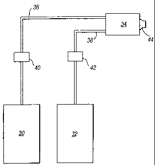
Figure 1 shows how such a liquid suppressant may be deployed in mist form. As
shown
in Figure 1, the liquid suppressant is stored under pressure in a suitable
vessel 30. An
inert gas, typically nitrogen, is stored under pressure in a second vessel 32.
The vessels
30 and 32 are respectively connected to an output unit 34 by pipes 36 and 38
and control
valves 40 and 42. When the control valves 40 and 42 are opened, the liquid
suppressant
and the inert gas are fed under pressure to the output unit 34. The output
unit 34
comprises a hollow chamber into which the liquid suppressant and the inert gas
are
discharged. Within the mixing chamber, the gas and the liquid physically
interact and the
gas causes the suppressant to be formed into a mist made up of droplets of
small size,
preferably in the range ofbetween 5 and 60 micrometres. The mist is produced
partly by
a shearing action of the gas on the liquid suppressant. Within the unit 34,
the liquid
suppressant may enter in a direction substantially parallel to the direction
of the gas.
Instead, it can enter substantially at right angles to the gas and the
shearing action will be
greater. Another possibility is for the liquid suppressant to enter in a
direction opposite to
that of the gas, and the shearing action may be greater still. After the
liquid agent and
inert gas have been mixed, vapour from the liquid agent will also be formed.
The
resultant vapour and mist of the liquid suppressant together with the inert
gas, which
carries them, exits through a nozzle 44 into the volume or area to be
protected.
The combination of vapour and liquid mist dispersed in the inert gas now forms
a
suppression agent having some of the characteristics of a gaseous suppressant.
In
particular, because the vapour and mist are being carried by the inert gas
they can
CA 02442662 2009-04-28
14
perrneate and expand into all or most parts of the space or volume to be
protected and thus
provide a total flooding capability. The suppressant agent of course includes
nothing else
having any significant environmental impact and which has an atmospheric
lifetime
longer than 30 days.
The output unit 34 may be arranged to supply more than one nozzle 44. More
particularly, it may supply a pipework array with multiple nozzles.
Figure 2 shows another system for deploying such a liquid suppressant in mist
form and
carried by an inert gas, the system having similarities with the form
disclosed in our co-
pending United Kingdom patent applicatYon No. 0123146.3.
In Figure 2, a vessel 5 stores the liquid suppressant undcr pressure. The
vessel 5 is
connected to an input of a mixing unit 6 via a pressure regulator 8, a flow
regulator 10, a
pipe 12, and a nozzle 13.
The system also includes vessels 14 storing an inert gas such as nitrogen
which has an
outlet connected via a pressure regulator 16, a flow regulator 18 and a pipe
20 to another
input of the mixing unit 6. The mixing unit 6 has an outlet pipe 22 which
connects with
the distribution pipe 24 terminating in spreader or distribution heads 26, 28.
The liquid
suppressant in the vessel5 may be pressurised by the gas in the vessels 14 via
a pipe 29.
However, it may be pressurised in some other way.
CA 02442662 2003-09-29
WO 02/078790 PCT/GB02/01476
In use, the liquid suppressant from the vessel 5 is fed under pressure into
the mixing unit
6 and enters the mixing unit 6 via the nozzle 13 which is arranged to convert
the liquid
suppressant into a mist of droplets of small size, again preferably in the
range of between
5 and 60 micrometers. The mist may be produced simply by the step of forcing
the liquid
through the nozzle 13. Instead, the nozzle may incorporate means such as a
rotary
atomising disk to produce or augment the misting process.
Additionally, the mist of the liquid suppressant is mixed within the mixing
chamber 6
with inert gas and becomes disposed as a suspension within the gas. Vapour is
also
formed as the liquid droplets evaporate by virtue of their high surface area
to volume
ratio.
The mist and vapour carried by the inert gas exit the mixing chamber 6 along
the outlet
pipe 22 to a T junction 23 and thence along the distribution pipe 24, and exit
from the
spreaders 26, 28 into the volume to be protected.
In the system of Figure 2, it is an important feature that the mixing unit 6
in which the
mist is produced is separate from and distanced from the outlets or spreaders
26, 28. The
mist and vapour exiting the mixing unit 6 moves at high velocity and is
entrained by and
within the high pressure gas. The resultant turbulence in the pipe 22 helps to
reduce the
size of the droplets in the mist and form vapour. The already-formed high
velocity mist
and vapour exit the spreaders as a two-phase mixture which consists of the
inert gas
carrying fine droplets and vapour of the liquid chemical extinguishant. The
gas continues
CA 02442662 2003-09-29
WO 02/078790 PCT/GB02/01476
16
to expand, on exiting the spreaders 26, 28, producing an even mixture - which
thus acts
again as a total flooding agent.
The presence of the inert gas in the discharged mist increases the efficiency
of the
extinguishing and suppression action because the inert gas is a suppressant in
its own
right.
The systems described above with reference to Figures 1 and 2 have used
nitrogen as the
inert gas. Other suitable gases are argon, helium, neon and carbon dioxide or
mixtures
from any two or more of these gases and nitrogen. However, any other suitable
gas or gas
mixture may be used which is non-combustible or is effectively inert in a
flame.
The extinguishants can have the advantage of being clean agents in that they
leave no
residue after deployment.
A mixture of the suppressants can be used.
Such systems as described with reference to Figures 1 and 2 can have fire
suppressant
properties similar or equivalent to those which use known total flooding
extinguishing
agents. They may have applications as an alternative to fixed fire suppression
systems
using Halons, perfluorocarbons, hydrofluorocarbons and
hydrochlorofluorocarbons.