Note : Les descriptions sont présentées dans la langue officielle dans laquelle elles ont été soumises.
CA 02445829 2003-10-27
WO 02/088580 PCT/IT02/00275
pressure actuated shut-off valve with membrane
TECHNICAL FIELD
The present invention relates to an ON/OFF valve, in
particular for use in water circulation conduits of
household coffee machines.
BACKGROUND ART
Valves of the above type are known which
substantially comprise an outer casing defining a water
flow cavity; a disk-shaped base member,.which is inserted
hermetically inside the cavity, and defines an
intermediate opening section permitting water flow
between a first and a second chamber of the cavity
separated by the base member; and a flexible shutter
having -a stem fitted coaxially through the base member,
and a membrane portion which projects radially from the
end of the stem facing the first chamber, and cooperates
elastically, by virtue of fluid pressure, with the
opening section to separate the first and second chamber
hermetically.
Valves of the above type are normally used to permit
one-way water flow, and, in particular, are maintained in
CA 02445829 2009-02-04
2
a closed configuration when the pressure in the first chamber is greater than
that in the second
chamber.
DISCLOSURE OF THE INVENTION
It is an object of the present invention to provide an ON/OFF valve which is
structurally as
straightforward as the type described above, but which pennits two-way flow
between the chambers
eonnection by the valve, when the pressure difference between the chambers is
below a
predetermined threshold value other than zero.
According to the present invention, there is provided an ON/OFF valve
comprising: an outer body
defining a fluid flow cavity divided by an intermediate surface into a first
and a second chamber
communicating with each other via an opening section in the intermediate
surface; and a flexible
shutter having, on a side facing said first chamber, a membrane portion
cooperating elastically, by
virtue of a fluid pressure, with said intermediate surface and with said
opening section to separate
said first and said second chamber hermetically; said valve further comprising
fluid leakage
generating means located between said membrane portion of said shutter and
said opening section,
and which are active when the pressure in said first chamber exceeds the
pressure in said second
chamber by an amount equal to or less than a threshold value other than zero,
wherein said fluid
leakage generating means comprise at least one groove formed in said
intermediate surface and
communicating with said opening section; said threshold value being a function
of the geometry of
said groove.
BRIEF DESCRIPTION OF THE DRAWINGS
Three preferred, non-limiting embodiments of the present invention will be
described by way of
example with reference to the accompanying drawings, in which:
Figure I shows an axial section of an ON/OFF valve in accordance with the
present invention;
Figure 2 shows an exploded view in perspective of an inner portion of the
Figure I valve;
Figure 3 shows a plan view of the assembly sequence of the inner portion of
the valve in Figures I
and 2;
Figure 4 shows an exploded axial section of the inner portion of the Figure I
valve;
Figure 5 shows a side view of the inner portion of the Figure I valve in a
closed configuration;
Figure 6 shows a section along line VI-VI in Figure 5;
Figure 7 shows a side view of the inner portion of
CA 02445829 2003-10-27
WO 02/088580 PCT/IT02/00275
3
the Figure 1 valve in a leakage configuration;
Figure 8 shows a section along line VIII-VIII in
Figure 7;
Figure 9 shows an exploded view in perspective of a
further embodiment of the inner portion of an ON/OFF
valve in accordance with the present invention;
Figure 10 shows an axial section of a further
embodiment of an ON/OFF valve in accordance with the
present invention;
Figure 11 shows an exploded view in perspective of
the Figure 10 valve.
BEST MODE FOR CARRYING OUT THE INVENTION
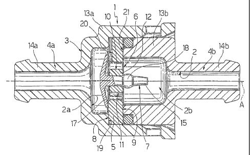
With reference to Figures 1 to 8,',, number 1
indicates as a whole an ON/OFF valve in accordance with
the present invention, and particularly suitable for use
in the water circulation conduits of a household coffee
machine.
Valve 1 has an axis A, and substantially comprises
an outer casing 3 defining a cavity 2 for the passage of
fluid - in the example shown, water; a disk-shaped base
member 5 housed hermetically inside cavity 2 to divide
the cavity into two separate chambers 2a, 2b, and having
an opening section 6 permitting fluid flow through cavity
2; and a flexible shutter 7 carried by member 5 and
cooperating elastically, by virtue of fluid pressure,
with opening section 6 to separate chambers 2a and 2b
hermetically.
More specifically, casing 3 is defined by two
CA 02445829 2003-10-27
WO 02/088580 PCT/IT02/00275
4
fittings 4a, 4b, which click together hermetically and
are connected to respective water circulation conduits
(not shown).
More specifically, fittings 4a, 4b have respective
cylindrical, cup-shaped main portions 13a, 13b connected
to each other, and from which project respective
cylindrical, tubular endpieces 14a, 14b, which are
smaller in section than main portions 13a, 13b, and are
connected to the water circulation conduits.
One (4b) of fittings 4a, 4b is mounted with its main
portion (13b) inside the main portion (13a) of the other
fitting (4a).
Base member 5 is locked axially betweenr;an annular
shoulder 19 of main portion 13a of fitting 4a and an
annular end surface 21 of main portion 13b of fitting 4b,
so that chambers 2a and 2b are defined by fittings 4a and
4b respectively. Base member 5 is defined towards
chambers 2a, 2b by respective end surfaces 8, 9.
Opening section 6 is formed in an intermediate
position through base member 5, and is defined by two
substantially half-moon--shaped through openings 10, 11
defining, on opposite sides, a seating portion 12 for
shutter 7.
As shown, particularly in Figure 3, openings 10, 11
and seating portion 12 lie within a circular area of axis
A, the edge of which is defined on diametrically opposite
sides by the peripheral edges of openings 10, 11.
Shutter 7 - which is preferably made of organic
CA 02445829 2003-10-27
WO 02/088580 PCT/IT02/00275
polymer, e.g. silicone-base, material compatible with use
in contact with food products - comprises a stem 15
fitted through a hole 16 of axis A in seating portion 12
of base member 5; and a circular membrane portion 17
5 projecting radially from one end of stem 15, and which
cooperates elastically with end surface 8 of base member
5 about opening section 6.
In the example shown, stem 15 of shutter 7 extends
through hole 16 in base member 5 and projects inside
chamber 2b, while membrane portion 17 is housed inside
chamber 2a.
On the opposite side to membrane portion 17, stem 15
has a spherical projection 18, which, in. use, projects
inside chamber 2b, and rests against end surface 9 of
base member 5 and about the edge of hole 16 to prevent
axial withdrawal of shutter 7.
Membrane portion 17 of shutter 7 is dome-shaped and
convex on the side facing chamber 2a.
An important aspect of the present invention is that
base member 5 comprises, along end surface 8, a lateral
groove 20 communicating with opening section 6 to allow
fluid to leak through base member 5 when the pressure in
chamber 2a exceeds the pressure in chamber 2b by an
amount equal to or less than a threshold value P,
depending on the geometry of groove 20.
More specifically, groove 20 has an open U-shaped
cross section, and extends radially from opening section
6 to a peripheral edge of base member 5. More
CA 02445829 2003-10-27
WO 02/088580 PCT/IT02/00275
6
specifically, groove 20 extends from a radially-outer
peripheral edge of opening 11, and projects radially with
respect to membrane portion 17.
In actual use, when the pressure in chamber 2a
exceeds the pressure in chamber 2b by an amount greater
than threshold value P, membrane portion 17 adheres to
end surface 8 of base member 5, and also to groove 20,
thus separating chambers 2a and 2b hermetically (Figures
5 and 6).
Conversely, when the difference between the pressure
in chamber 2a and the pressure in chamber 2b is equal to
or less than threshold value P, membrane portion 17 is
detached from groove 20 in end surface 8 to '-allow fluid
to leak between chambers 2a and 2b (Figures 7 and 8).
This may be employed to prevent fluid from stagnating in
chamber 2a when the pressure in chamber 2a falls, e.g. as
when a delivery pump connected to cavity 2 is turned off;
in which case, chambers 2a and 2b no longer need
separating. Valve 1 therefore provides for better meeting
the functional requirements of hydraulic systems.
Obviously, the maximum difference in pressure
between chambers 2a and 2b governing two-way flow through
cavity 2 is adjustable by adjusting the depth and
geometry of groove 20.
Number 1' in Figure 9 and number 1" in Figures 10
and 11 indicate as a whole two further embodiments of
ON/OFF valves in accordance with the teachings of the
present invention, and any parts of which identical with
CA 02445829 2003-10-27
WO 02/088580 PCT/IT02/00275
7
or, equivalent to those of valve 1 already described are
indicated, where possible, using the same reference
numbers.
Valve 1' (Figure 9) differs from valve 1 by
comprising a number of - preferably three - grooves 20
equally spaced angularly about axis A, and by opening
section 6 of base member 5 being defined by three through
openings 25 equally spaced angularly about hole 16 and
communicating with grooves 20.
Threshold value P therefore depends not only on the
geometry but also on the number of grooves 20.
Valve 1" (Figures 10 and 11) differs from valve 1 by
having no disk-shaped member 5, and by chamber 2b of
fitting 4b defining a seat 26 housing a cylindrical coil
spring 27, which acts on shutter 7 to keep it in an open
configuration permitting fluid flow through cavity 2 when
the pressure in chamber 2a exceeds the pressure in
chamber 2b by an amount equal to or less than a threshold
value P depending on the load of spring 27.
More specifically, stem 15 of shutter 7 loosely
engages spring 27 and seat 26 in fitting 4b, while
membrane portion 17, projecting inside chamber 2a, is
positioned contacting one end of spring 27, and
cooperates elastically with end surface 21 of main
portion 13b of fitting 4b. In this case, chambers 2a and
2b communicate via a central opening 28 formed in end
surface 21 and which is closed hermetically by membrane
portion 17 of shutter 7 when, as already explained, the
CA 02445829 2003-10-27
WO 02/088580 PCT/IT02/00275
8
pressure in chamber 2a exceeds the pressure in chamber 2b
by an amount greater than threshold value P.
In the open configuration of shutter 7, spring 27
keeps membrane portion 17 detached by a predetermined
amount from end surface 21 of fitting 4b, so that
chambers 2a and 2b communicate via opening 28.
Valve 1" operates in exactly the same way as valves
1 and 1'.
More specifically, when the pressure in chamber 2a
exceeds the pressure in chamber 2b by an amount greater
than threshold value P, membrane portion 17 compresses
spring 27 and adheres to end surface 21 of fitting 4b to
separate chambers 2a and 2b hermetically.
Clearly, changes may be made to valves 1, 1', 1"
according to the present invention, without, however,
departing from the scope of the accompanying Claims.