Sélection de la langue

Search

Sommaire du brevet 2446446 

Énoncé de désistement de responsabilité concernant l'information provenant de tiers

Une partie des informations de ce site Web a été fournie par des sources externes. Le gouvernement du Canada n'assume aucune responsabilité concernant la précision, l'actualité ou la fiabilité des informations fournies par les sources externes. Les utilisateurs qui désirent employer cette information devraient consulter directement la source des informations. Le contenu fourni par les sources externes n'est pas assujetti aux exigences sur les langues officielles, la protection des renseignements personnels et l'accessibilité.

Disponibilité de l'Abrégé et des Revendications

L'apparition de différences dans le texte et l'image des Revendications et de l'Abrégé dépend du moment auquel le document est publié. Les textes des Revendications et de l'Abrégé sont affichés :

  • lorsque la demande peut être examinée par le public;
  • lorsque le brevet est émis (délivrance).
(12) Brevet: (11) CA 2446446
(54) Titre français: PROCEDE ET DISPOSITIF POUR LA GENERATION D'OZONE
(54) Titre anglais: METHOD AND DEVICE FOR GENERATING OZONE
Statut: Réputé périmé
Données bibliographiques
(51) Classification internationale des brevets (CIB):
  • C01B 13/11 (2006.01)
(72) Inventeurs :
  • BILLING, ERNST MARTIN (Allemagne)
  • FIEKENS, RALF (Allemagne)
  • HOFER, UWE (Allemagne)
(73) Titulaires :
  • WEDECO GESELLSCHAFT FUR UMWELTTECHNOLOGIE MBH (Allemagne)
(71) Demandeurs :
  • WEDECO GESELLSCHAFT FUR UMWELTTECHNOLOGIE MBH (Allemagne)
(74) Agent: RIDOUT & MAYBEE LLP
(74) Co-agent:
(45) Délivré: 2008-12-09
(86) Date de dépôt PCT: 2002-05-24
(87) Mise à la disponibilité du public: 2002-12-05
Requête d'examen: 2004-04-07
Licence disponible: S.O.
(25) Langue des documents déposés: Anglais

Traité de coopération en matière de brevets (PCT): Oui
(86) Numéro de la demande PCT: PCT/DE2002/001890
(87) Numéro de publication internationale PCT: WO2002/096798
(85) Entrée nationale: 2003-11-05

(30) Données de priorité de la demande:
Numéro de la demande Pays / territoire Date
101 25 823.2 Allemagne 2001-05-26

Abrégés

Abrégé français

L'invention concerne un procédé pour la génération d'ozone à partir de gaz contenant de l'oxygène. L'ozone est généré par décharge électrique silencieuse dans un ensemble comprenant au moins deux entrefers traversés par le gaz et formés chacun entre une électrode et un diélectrique qui sépare l'entrefer correspondant d'une autre électrode. Selon l'invention, un étranglement du débit volumétrique du gaz d'au moins un entrefer est commandé.


Abrégé anglais


The invention relates to a method for generating ozone from gases containing
oxygen. The ozone is generated by
silent electric discharge in an installation comprising at least two gaps,
which are traversed by the gas, each of said gaps being formed
between an electrode and a dielectric that separates each gap from an
additional electrode. According to the invention, the restriction
of the volumetric flow of the gas of at least one gap is controlled.

Revendications

Note : Les revendications sont présentées dans la langue officielle dans laquelle elles ont été soumises.


CLAIMS


1. A method for generating ozone from oxygen-containing
gases by silent electric discharge in an installation
comprising at least two gaps (16, 18), which are
traversed by the gas, each of said gaps being formed
between an electrode (10, 12) and a dielectric (14)
that separates each gap (16, 18) from an additional
electrode (12; 10), characterised in that a
distribution of the total volumetric flow of the gas
between the gaps (16, 19) is controlled by a
concentrated restriction of the volumetric flow of the
gas of at least one gap (16, 18) at the inlet or
outlet or inside the gap (16, 18) or of a
subcombination at the inlet and outlet or at the inlet
and inside the gap (16, 18) or at the outlet and
inside the gap (16, 18) or at the inlet and outlet and
inside the gap (16, 18).

2. The method according to claim 1, characterised in that
a distribution of the total volumetric flow of the gas
between the gaps (16, 18) is additionally controlled
by an elongated restriction of the volumetric flow of
the gas at least inside a gap (16, 18).

3. A device for generating ozone from oxygen-containing
gases by silent electric discharge in an installation
comprising at least two gaps (16, 18), which are
traversed by the gas, each of said gaps being formed
between an electrode (10, 12) and a dielectric (14)
that separates each gap (16, 18) from an additional
electrode (12; 10), characterised in that at least one
gap (16, 18) comprises a concentrated throttle (20)
for restriction of the volumetric flow of the gas at
the inlet or outlet or inside the gap (16, 18) or
concentrated throttles (20) at the inlet and outlet or
at the inlet and inside the gap (16, 18) or at the


-2-

outlet and inside the gap (16, 18) or at the inlet and
outlet and inside the gap (16, 18).

4. The device according to claim 3, characterised in that
at least one gap (16, 18) additionally comprises an
elongated throttle.

5. The device according to claim 4, characterised in that
the elongated throttle is formed by a profiling of the
surface of the electrode and/or the dielectric
pointing towards the gap.

6. The device according to claim 3, characterised in that
the concentrated throttle (20) is constructed as a
sleeve extending substantially over the cross-section
of the gap (16, 18) through which gas can flow and/or
a stopper extending substantially over the cross-
section of the gap (16, 18) through which gas can
flow.

7. The device according to claim 6, characterised in that
the throttle (20) constructed as a sleeve or stopper
consists of a full-material body and extends
completely over the cross-section of the gap (16, 18)
and is provided with gas-permeable slits or holes
and/or extends over a partial cross-section of the gap
(16, 18).

8. The device according to any one of claims 3, 6 or 7
characterised in that the concentrated throttle (20)
is annular-shaped and is arranged in a first and/or
second gap (16, 18) wherein the first gap (16) is
formed by a cylindrical annulus formed between a first
electrode (10) and a dielectric (14) and the second
gap (18) is formed by a cylindrical annulus enclosed
between the dielectric (14) and a second electrode
(12).


-3-

9. The device according to any one of claims 3 or 6 to 8,
characterised in that the throttle (20) comprises an
integrated high-voltage fuse.

10. The device according to any one of claims 3 or 6 to 9,
characterised in that the throttle (20) consists of an
oxygen- and ozone-resistant material.

11. The device according to any one of claims 3 or 6 to
10, characterised in that the throttle (20) and the
first and second electrodes (10, 12) and the
dielectric (14) are plate-shaped.

12. The device according to any one of claims 3 to 13,
characterised in that the distribution of the gas
volumetric flow in the gaps (16, 18) is adjustable by
the throttle (20) in a range of 20 to 80 %.

13. The device according to any one of claims 3 to 13,
characterised in that by individually dimensioning the
flow resistance of the throttle (20), structural
component tolerances having an influence on the ozone
yield can be compensated in one series of the device.

Description

Note : Les descriptions sont présentées dans la langue officielle dans laquelle elles ont été soumises.


CA 02446446 2003-11-05

METHOD AND DEVICE FOR GENERATING OZONE

The invention relates to a method for generating ozone
according to the preamble of claim 1 and adevice for
generating ozone according to the preamble of claim 3.
Ozone is a strong oxidising agent for organic substances
and for inorganic compounds in which elements having
several oxidation stages are present. Of the numerous
applications for this oxidising agent, over the last few
years applications for water treatment in particular have
been intensively further developed.

Ozone is generated by electric discharge in an oxygen-
containing gas. The so-called silent discharge represents a
stable plasma or corona discharge in contrast to the spark
discharge. In this case molecular oxygen is dissociated
into atomic oxygen. The reactive oxygen atoms thus formed
are added to the existing oxygen molecules in an exothermic
reaction and thus form the tri-atomic ozone molecule.

Important parameters for the efficiency of the overall
reaction chain are the gas composition, the electric field
strength, the operating temperature and the operating
pressure of the ozone-generating system.

Over the last few years, as a result of technological
progress with manufacturing tolerances increasingly smaller
reaction gaps have been achieved, which influence both the
field strength and the temperature established in the gap.
Gap widths of 250 m are now state of the art.

A device of the type specified initially is known from WO
97/09268. The device comprises an arrangement with at least
one gap through which the gas flows, which is formed
between an electrode and a dielectric that separates the
gap from another electrode. At least one of the gaps is


CA 02446446 2003-11-05

- 2 -

filled with an electrically conductive and thermally
conductive gas-permeable arrangement which is in electrical
and thermal contact with the adjacent electrode and through
which the oxygen-containing gas flows and which forms a
plurality of discharge spaces in which the oxygen-
containing gas is exposed to a high field strength and is
converted into ozone.

The electrically and thermally conductive gas-permeable
arrangement described there at least completely fills one
gap and preferably comprises wire which is constructed as
knit.

By adapting the mesh number, mesh size, and wire thickness
as well as the knit density, the number of knit wires and
the number of knit layers, it is possible to establish the
flow resistance of the arrangement, to adapt the size of
the discharge spaces for maximal ozone production, to
regulate the turbulence and intermixture of the gas, and to
optimise cooling and heat dissipation.

Starting from this prior art, the object of the invention
is generally to provide a method and a suitable device with
which the ozone yield can be significantly increased for
comparable energy input.

This object is solved by a method according to the preamble
of claim 1 and a device according to the preamble of claim
3 by the features specified in the respective
characteristic.

In the method according to the invention a distribution of
the total volumetric flow of gas between the gaps is
'controlled by a concentrated restriction of the volumetric
flow at least of one gap.


CA 02446446 2003-11-05

- 3 -

As a result of the specific adjustment of the gas
distribution between the gaps according to the invention,
an increase in the efficiency of ozone generation is
achieved taking into account gap optimisations with regard
to the physical effects used, the field strength profile
and the temperature profiles. It was found that by
specifically influencing the volumetric flow of gas with a
given gap geometry and given electrical/physical operating
conditions, it is possible to optimise the ozone yield
compared to the electrical energy used.

If two gaps are used through which gas flows in parallel,
optimisation can conventionally only be achieved for one of
the gaps or for an average of the two gaps. As a result of
the measure according to the invention, it was possible to
perform an optimisation for each of the gaps, whereby the
total ozone yield is increased further compared to the
electrical energy used.

The method according to the invention can be used for
systems in which two or a plurality of gaps are used for
the discharge. In such a multi-gap system certain
advantages of individual gaps can be brought out by the
defined distribution of the total volumetric flow of the
gas. Thus, for example, it is possible to set the field
strength profile as the base parameter in order to force a
distribution of the total volumetric flow of gas onto a gap
such that the energetically most favourable gap can
generate most of the ozone.

Practice has shown that in conventional devices having at
least two gaps arranged in parallel the distribution of the
total volumetric flow of gas between the gaps is
substantially imprinted by the geometry of the gaps itself.
No method which can control the distribution of the total
volumetric flow of gas is known. Using a knit completely
filling the gap, as described in w0 97/09268, a defined


CA 02446446 2003-11-05
- 4 -

distribution of the total volumetric flow can be achieved
with only a slight variation of around 2 to 8 %.

Optimising only one gap with regard to an increase in the
efficiency of ozone generation, for example, by reducing
the gap width, in the same way has an effect on the
corresponding gap and results in no significant change in
the ozone yield overall.

In order to implement the method according to the invention
a concentrated restriction of the volumetric flow of the
gas of at least one gap is made. Concentrated restriction
is understood to mean that the throttle section has a
length substantially smaller than the length of the gap.
The restriction can take place at the inlet or outlet or
inside the gap or a subcombination at the inlet and outlet
or at the inlet and inside the gap or at the outlet and
inside the gap or at the inlet and outlet and inside the
gap .

In addition, a distribution of the total volumetric flow of
the gas between the gaps can be additionally controlled by
an elongated restriction of the volumetric flow of gas at
least within one gap. Elongated restriction is understood
to mean a length of throttle section which extends over the
total length or at least 20% of the length of the gap.

The device according to the invention is characterised in
that at least one gap comprises a concentrated throttle
which leads to a defined distribution of the total
volumetric flow of gas between the gaps.

The volumetric flow is in this case inversely proportional
'to the flow resistance brought about by the concentrated
throttle in the gap. The total volumetric flow is made up
of the individual volumetric flows of the gaps. Depending
on the configuration of the restriction, a defined


CA 02446446 2003-11-05

- 5 -

distribution of the total volumetric flow of gas between
the gaps can thus be established.

In addition, at least one gap can additionally comprise an
elongated throttle. In this case, the elongated throttle
can be formed by a profiling of the surface of the
electrode and/or dielectric pointing towards the gap. It is
thereby possible to divide up the throttle effect and
achieve a fine adjustment with the concentrated throttle.
The concentrated throttle can comprise a sleeve extending
substantially over the cross-section of the gap through
which gas can flow and/or a stopper extending substantially
over the cross-section of the gap through which gas can
flow.

With this configuration a pressure drop leads to a defined
distribution of the total volumetric flow of the gas
between the gaps.

The throttle formed as a sleeve or' stopper preferably
consists of a full-material body. This extends completely
over the cross-section of the gap and is provided with gas-
permeable slits or holes and/or extends over a partial
cross-section of the gap. The throttle effect of the full-
material body thus formed is based on a nozzle effect.

In an advantageous development of the invention, the
concentrated throttle is annular-shaped and arranged in a
first and/or second gap. In this case, the first gap is
formed by a cylindrical annulus formed between a first
electrode and a dielectric and the second gap is formed by
a cylindrical annulus enclosed between the dielectric and a
second electrode.

In such an arrangement the volumetric flow of gas is only
distributed over two gaps. In this case, the distribution


CA 02446446 2003-11-05

- 6 -

of the volumetric flow of gas can be controlled especially
easily to increase the ozone yield.

A further development provides that the throttle comprises
an integrated high-voltage fuse. In order to avoid damage
to the device, especially the electrode surface, the
dielectric or the high-voltage generator, a separate fuse
can thereby be dispensed with.

The body suitably consists of oxygen- and ozone-resistant
material. This measure provides constant ozone-generating
properties and freedom from maintenance.

As an alternative to the cylindrically symmetrical
arrangement of the invention it is provided that the
throttle and the first and second electrode and the
dielectric are constructed as plate-shaped.

According to an advantageous development of the invention
the distribution of the volumetric flow of gas between the
gaps can be adjusted in a range of 20 'to 80 % which leads
to a substantial increase in efficiency compared with the
prior art.

A particular advantage of the invention is that by
individually dimensioning the flow resistance of the
throttles, structural component tolerances influencing the
ozone gas yield in one series of the device can be
compensated.

This helps to reduce the waste fractions during production
and allows the manufacture of apparatus having narrow
tolerances of the characteristic values and thus precisely
calculable characteristic values of complete installations.


CA 02446446 2003-11-05

- 7 -

The invention is explained below with reference to
exemplary embodiments shown in the drawings. In the
figures:

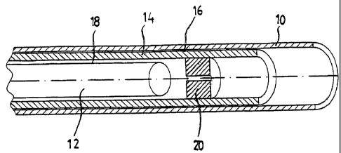
Fig. 1 shows a part-perspective sectional view of a
device in a cylindrically symmetrical arrangement
with a throttle constructed as a stopper and

Fig. 2 shows a part-perspective sectional view of a
device in a cylindrically symmetrical arrangement
with a throttle constructed as a sleeve.

Figures 1 and 2 show a special cylindrically symmetrical
arrangement of the device. A first outer electrode 10 which
is at reference potential, has a cylindrical dielectric 14
inside and this in turn has a second inner electrode 12
which is at high-voltage potential. Gaps 16, 18 are formed
both between the first electrode 10 and the dielectric 14
and between the dielectric 14 and the second electrode 12.
A throttle 20 is arranged in the inner gap 18. In Fig. 1
this throttle 20 is constructed in the form of a stopper
through which gas can flow, located before the second
electrode 12, in the fashion of a nozzle. The stopper is
arranged at the end of the inner gap 18. On the other hanb,
the throttle 20 according to Fig. 2 is constructed in the
form of a sleeve enclosing the second electrode 12 in the
head region and through which gas can flow.

Stopper and sleeve only fill part of the inner gap 20 and
result in restriction of the gap volume. A defined
distribution of the volumetric flow of gas between the gaps
16, 18 is thereby achieved.

The gas flowing through the device is opposed by a flow
resistance as a result of the throttle 20 which results in
a defined distribution of the total volumetric flow of gas


CA 02446446 2003-11-05

- 8 -

between the gaps depending on the arrangement of the
throttle 20. As a result of the distribution of the
volumetric flow of gas between the gaps an increase in the
efficiency of the ozone yield of up to 15 % is achieved
compared with the prior art.

Dessin représentatif
Une figure unique qui représente un dessin illustrant l'invention.
États administratifs

Pour une meilleure compréhension de l'état de la demande ou brevet qui figure sur cette page, la rubrique Mise en garde , et les descriptions de Brevet , États administratifs , Taxes périodiques et Historique des paiements devraient être consultées.

États administratifs

Titre Date
Date de délivrance prévu 2008-12-09
(86) Date de dépôt PCT 2002-05-24
(87) Date de publication PCT 2002-12-05
(85) Entrée nationale 2003-11-05
Requête d'examen 2004-04-07
(45) Délivré 2008-12-09
Réputé périmé 2016-05-24

Historique d'abandonnement

Il n'y a pas d'historique d'abandonnement

Historique des paiements

Type de taxes Anniversaire Échéance Montant payé Date payée
Le dépôt d'une demande de brevet 300,00 $ 2003-11-05
Requête d'examen 800,00 $ 2004-04-07
Taxe de maintien en état - Demande - nouvelle loi 2 2004-05-25 100,00 $ 2004-04-08
Enregistrement de documents 100,00 $ 2004-05-21
Taxe de maintien en état - Demande - nouvelle loi 3 2005-05-24 100,00 $ 2005-05-03
Taxe de maintien en état - Demande - nouvelle loi 4 2006-05-24 100,00 $ 2006-05-03
Taxe de maintien en état - Demande - nouvelle loi 5 2007-05-24 200,00 $ 2007-05-01
Taxe de maintien en état - Demande - nouvelle loi 6 2008-05-26 200,00 $ 2008-05-01
Taxe finale 300,00 $ 2008-09-24
Taxe de maintien en état - brevet - nouvelle loi 7 2009-05-25 200,00 $ 2009-04-30
Taxe de maintien en état - brevet - nouvelle loi 8 2010-05-24 200,00 $ 2010-04-30
Taxe de maintien en état - brevet - nouvelle loi 9 2011-05-24 200,00 $ 2011-05-02
Taxe de maintien en état - brevet - nouvelle loi 10 2012-05-24 250,00 $ 2012-04-30
Taxe de maintien en état - brevet - nouvelle loi 11 2013-05-24 250,00 $ 2013-04-30
Taxe de maintien en état - brevet - nouvelle loi 12 2014-05-26 250,00 $ 2014-05-19
Titulaires au dossier

Les titulaires actuels et antérieures au dossier sont affichés en ordre alphabétique.

Titulaires actuels au dossier
WEDECO GESELLSCHAFT FUR UMWELTTECHNOLOGIE MBH
Titulaires antérieures au dossier
BILLING, ERNST MARTIN
FIEKENS, RALF
HOFER, UWE
Les propriétaires antérieurs qui ne figurent pas dans la liste des « Propriétaires au dossier » apparaîtront dans d'autres documents au dossier.
Documents

Pour visionner les fichiers sélectionnés, entrer le code reCAPTCHA :


Pour visualiser une image, cliquer sur un lien dans la colonne description du document. Pour télécharger l'image (les images), cliquer l'une ou plusieurs cases à cocher dans la première colonne et ensuite cliquer sur le bouton "Télécharger sélection en format PDF (archive Zip)" ou le bouton "Télécharger sélection (en un fichier PDF fusionné)".

Liste des documents de brevet publiés et non publiés sur la BDBC .

Si vous avez des difficultés à accéder au contenu, veuillez communiquer avec le Centre de services à la clientèle au 1-866-997-1936, ou envoyer un courriel au Centre de service à la clientèle de l'OPIC.


Description du
Document 
Date
(yyyy-mm-dd) 
Nombre de pages   Taille de l'image (Ko) 
Abrégé 2003-11-05 1 65
Dessins 2003-11-05 1 19
Revendications 2003-11-05 3 115
Description 2003-11-05 8 336
Dessins représentatifs 2003-11-05 1 10
Page couverture 2004-01-21 1 39
Description 2008-02-15 8 322
Revendications 2008-02-15 3 94
Dessins représentatifs 2008-11-21 1 11
Page couverture 2008-11-21 1 40
PCT 2003-11-05 6 194
Cession 2003-11-05 3 108
Correspondance 2004-01-19 1 26
Taxes 2004-04-08 1 32
Poursuite-Amendment 2004-04-07 1 41
Cession 2004-05-21 2 77
Taxes 2005-05-03 1 28
Poursuite-Amendment 2007-09-04 2 74
Taxes 2006-05-03 1 26
Taxes 2007-05-01 1 29
Poursuite-Amendment 2008-02-15 9 297
Taxes 2008-05-01 1 38
Correspondance 2008-09-24 1 33