Note : Les descriptions sont présentées dans la langue officielle dans laquelle elles ont été soumises.
CA 02447374 2003-10-30
1
IMPROVED STEEL ,!01ST
FIELD OF THE INVENTION
The present invention generally relates to an improved steel joist. More
particularly, it relates to a steel joist having a flared top chord which can
be
used as part of a composite floor system for use in the construction of
buildings.
BACKGROUND OI= THE INVENTION
Floor construction in building projects can involve the use of steel joists
placed in different positions spanning structural supports and a concrete
slab subsequently poured on decking supported by the joists. The slab
and the joist form a composite structure having superior strength properties
compared to a conventional non-composite floor system. Generally, the
joist is in the form of a truss having top and bottom chords which are
connected by a web. The web itself can vary in design from being
constructed of solid material to comprising tension and compression
members triangulating the space between the top and bottom chords.
United States Patent No. 4,729,201 granted to Laurus et al. discloses a
joist consisting of a web, a bottom chord and a double top chard
construction consisting of two elongated substantially identical portions
each being of S cross-section, extending the length of the joist. This
design of the top chord improves the lateral stiffness which improves the
strength of the composite structure during construction stages and permits
safer construction procedures particularly where fang spans are involved.
The symmetry of the top chord provides structural advantages during the
installation stage where the unpropped joist is required to carry the weight
of wet concrete, form work, its own weight and other construction live
loads. The serpentine top chord profile provides a cross-sectional area
whereby the resulting lateral slenderness properties of the joist are
CA 02447374 2003-10-30
2
improved and the joist is consequently stiffened. The increased stiffness
improves the resistance of the joist to compressive stresses.
A symmetrical shape of the joist also helps avoid such problems as sweep.
Sweep is a phenomenon that is encountered during construction of a
welded joint between the chord and the web of the joist, where all welds
are made on one side of the web. This welding can create a stress in the
joint which tends to result in a certain amount of curvature in the completed
joisfi. This curvature can be avoided but would previously require a pre-
curving of the top chord in a direction opposite of that of the sweep effect.
The pre-curving of the top chord results in a substantially straight
longitudinal configuration for the completed joist once welded together. A
symmetrical top chord avoids this entire problem of sweep as a straight
joint is obtained without the necessity for complicated pre-assembly
compensation techniques. A symmetry in the top chord also doubles the
amount of shear bond between the joist and the concrete slab.
However, during the fabrication process for steel joists, getting access to
the area to be welded between the chord and the web element remains a
challenge due to the overall shape of the serpentine top chords that are
currently used in different joist designs. The shape of the top chord in
these designs prevents the welding tool from being inserted between the
two leg elements of the chord from a point directly above the joist and
therefore complicates the joist welding process during manufacturing of
joists in an assembly line context.
Thus, there is still presently a need for a top chord design that would
facilitate this welding process during fabrication of joists without losing
the
advantages of symmetrical top chords .
SUMMARY OF THE INVENTION
An object of the present invention is to propose a steel joist that satisfies
the above mentioned need.
CA 02447374 2003-10-30
3
Another object is to propose a steel joist design that facilitates the
fabrication process of steel joists by improving access of the welding tool to
the area between the symmetrical portion of the top chord and the web
member that must be joined together.
According to the present invention, that object is achieved with a flared fop
chord symmetrical shape design.
More particularly, the present invention provides a joist suitable for use in
a
composite concrete floor. The joist comprises a top chord, a bottom chord;
and a vertically extending intermediate web having a top end secured to
the top chord and a bottom end secured to the bottom chord. The top
chord is characterized in that it comprises a pair of longitudinally
continuous symmetrical chord members facing each other and embracing
the top end of the web. Each of the chord members includes a vertical
portion secured to the top end of the web and a slanting upper extension
extending above and away from the fop end of the web, thereby providing
a shear connecting portion and a flared opening between the two facing
chord members giving access to the web. This flared opening facilitates
insertion of a welding toot. The resulting opening is made sufficiently large
so that a welding tool can be easily inserted between the chord members
to create a welded joint between the vertical portion of the top chord
members and the web elements of the joist.
In accordance with a preferred aspect of the invention, the upper extension
of each chord member comprises a top end formed as a lip.
As in previous joist designs, the slanting extensions which are provided
with the lip provide shear connecting portions once it is embedded in the
concrete slab.
CA 02447374 2003-10-30
in accordance with a further preferred aspect, each of the chord members
comprises a groove between the vertical portion and the upper extension
to provide an additional ribbed member for compression portion and to
retain a closure element to hold the concrete in place during pouring of the
composite concrete floor.
Such grooves, than can also be referred to as dimples, benefit from an
increased cross-sectional area of the leg whereby the resulting lateral
slenderness properties of the joist are improved and the joist is
consequently stiffened, as is the case with joists using serpentine-shaped
top chords. These dimples can be added at specific locations, such as the
midpoint of the teg, to act as an alignment guide during fabrication of the
composite floor or to hold pour-stop closure elements in place during
pouring of the concrete slabs.
The two chord members, which can also be referred to as legs of the top
chord, extend outwardly in a symmetrical manner which will continue to
benefit from the advantages cited above for symmetrical top chords in prior
art, including an elimination or reduction of weld distortion and a full
utilization of both legs to create a shear bond between the joist and the
concrete slab.
In accordance with another preferred aspect, each of the symmetrical
chord members includes a horizontal shelf which allows the placement, as
well as the welding, nailing or screwing of a steel deck.
A non-restrictive description of a preferred embodiment of the invention will
now be given with reference to the appending drawings.
BRIEF ~ESCRIPTIt7N OF THE DRAWINGS
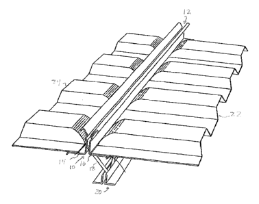
Figure 1 is a perspective view of a joist according to a preferred
embodiment of the invention, with corrugated decking placed on the
horizontal shelves of the tap chord.
CA 02447374 2003-10-30
Figure 2 is a cross-section view of a top portion of a joist according to the
invention showing more specifically the top chord.
Figure 3 is a partial cross-section view through a composite floor showing
the upper portion of two adjacent joists supporting a deck on both sides,
5 and a concrete slab poured onto the joists and deck to farm the composite
floor.
Figure 4 is a cross section view of a joist according to a second preferred
embodiment of the invention.
DESCRIPTION OF PREFERRED EMBODIMENTS
Referring to any one of figures 1 to 3, a steel joist (10) according to a
first
preferred embodiment of the invention comprises a top chord (12) including
two symmetrical chord members, hereinafter referred as leg members (14
and 16), which are attached to the web (18}. The joist (10) further
comprises a bottom chord {20) attached to the bottom part of the web (18)
and completes the I-beam-like design of the joist (10), the top chord (12)
and bottom chord (20) playing the role of top and bottom flanges
respectively for the beam. The top two leg members (14 and 16) support
the corrugated deck (22 and 24) elements.
Referring to figure 2, a top chord leg (16) comprises a horizontal shelf (26)
which supports the deck (22). The horizontal shelf {26) comprises a lip
(25) which stiffens the horizontal shelf (26) to provide a better distribution
of the load brought in by the deck (22) and to better resist stress
concentration points created by the nailing, welding or screwing of the deck
(22) to the horizontal shelf (26). It is however worth mentioning that,
instead of being provided with such a shelf, the top chord leg could
advantageously be provided with a substantially downward vertical
extension provided with openings, as in the joist described in US 4729201,
for receiving bars which serve to support form work, and that without
departing from the scope of the present invention. The top chord leg (16)
CA 02447374 2003-10-30
6
further comprises an upper slanting extension (29) provided with a lip (30)
that eventually becomes embedded in a concrete slab in the completed
composite floor system as will be described below. The top chord leg {16)
can also comprise a dimple (28) that can be added at specific locations of
the leg, such as its midpoint, to act as an alignment guide during
fabrication of the composite floor or to hold pour-stop closure elements in
place during pouring of the concrete slabs.
Figure 3 shows the interrelationship between the joist (10), the deck
elements (22 and 24) and the concrete slab (32) once the concrete slab
(32) is poured on the deck elements (22 and 24) and the joist (10). After
pouring of the concrete slab (32} on the deck elements (22 and 24}, the
upper extensions (27 and 29) with the lips (30 and 31 } of the top chord (12)
become embedded in the concrete slab (32} and form a composite floor
structure (34) having superior strength properties compared to a
conventional non-composite floor system as a shear connection is created
between the joist (10) and the concrete stab (32).
As can be appreciated, the flared design of the upper extensions (27 and
29) creates an opening {36) in the top chord {12) which is sufficiently large
to permit insertion of a welding tool between the two legs (14 and 1 C). This
new configuration of the upper extensions (27 and 29) allows an access of
the welding electrode through the top of the joist (10) to make satisfactory
welds at the welding points (38 and 40} between the top chord (12) and the
web member (18), which greatly simplifies manufacturing of the joist (10).
Although the present invention has been explained hereinabove by way of
preferred embodiments thereof, it should be understood that the invention
is not limited to these precise embodiments and that various changes and
modifications may be effected therein without departing from the scope or
spirit of the invention.