Note : Les descriptions sont présentées dans la langue officielle dans laquelle elles ont été soumises.
CA 02447496 2003-11-14
WO 02/093952 PCT/US02/15066
[0001] COMMON CONTROL CHANNEL UPLINK POWER CONTROL
FOR ADAPTIVE MODULATION AND CODING TECHNIQUES
[0002] FIELD OF THE INVENTION
[0003] The present invention relates to wireless digital communication
systems. More
particularly, the present invention is directed to a code division multiple
access
(CDMA) communication system utilizing uplink power control for adaptive
modulation and coding.
[0004] BACKGROUND
[0005] CDMA third generation (3G) cellular telecommunication systems apply
adaptive modulation and coding (AM&C) to transmissions to achieve and improve
radio resource utilization and provide increased data rates for user services.
AM&C
techniques take into account RF propagation conditions in advance of
transmissions in
order to determine modulation and coding rates that will take greatest
advantage of
current RF propagation conditions.
[0006] One method for determining RF propagation conditions is to perform a
physical
channel quality measurement at the receiver in advance of each transmission.
This
measurement is sent to the transmitter, which then determines the appropriate
modulation and coding rate for the particular transmission based upon the
physical
channel quality measurement.
[0007] RF propagation conditions can change rapidly, particularly for mobile
applications. Since the quality measurement of the radio interface is used to
determine
the appropriate modulation and coding, and since the channel quality
measurement can
change rapidly due to the changing RF propagation conditions, the performance
of the
adaptive transmission process is directly related to the time period (i.e.
latency)
between when a quality measurement is performed and when that transmission is
initiated. Therefore, for optimal AM&C, it is necessary to perform channel
quality
measurements with minimal latency for all users with active data
transmissions.
-1-
CA 02447496 2003-11-14
WO 02/093952 PCT/US02/15066
[0008] Physical or logical control channels are used to transfer channel
quality
measurements from a receiver to a transmitter. Channel quality signaling may
utilize
either dedicated control channels to each user equipment (UE) or common
control
channels shared by all UEs. When dedicated control channels are used, a
continuous
signaling channel is available over time for propagation of channel quality
measurements for each UE. In terms of performance, this is an optimal solution
for
AM&C since the quality measurement is continuously available. Transmissions
can
occur at any time, taking into account the continuously available quality
measurement
for appropriate modulation and coding settings. Additionally, with a dedicated
control
channel always available in the uplink, the channel can be also used to
support low
rate uplink data transmissions.
[0009] The difficulty with the dedicated control channel approach is that
physical
resources are continuously allocated even when there is no data to transmit. A
primary
application of AM&C techniques are non-real time high data rate services, for
example, Internet access. For these classes of service, the best quality of
service (QoS)
is achieved with short, high rate transmissions with relatively long idle
periods
between each transmission. These long idle periods result in an inefficient
use of
dedicated resources.
[0010] The problem can be minimized with pre-configured periodic dedicated
channel
allocations. But this results in periodic unavailability of quality
measurements. If the
quality measurements are not continuously available, for UEs which have
transmissions at any one point in time, only some portion of the UEs will have
recent
channel quality measurements.
[0011] When common control channels are used, a continuous signaling channel
is
shared by all UEs within a cell. In Third Generation-Time Division Duplex (3G
TDD) systems, the uplink common control channel typically occupies a single
time
slot out of multiple time slots. Procedures are defined for each UE's access
to the
common control channel and UE identities may be used to distinguish UE
specific
transactions.
-2-
CA 02447496 2010-07-13
[0012] To avoid contention-based access to the uplink common control channel,
individual
allocations are required to be signaled on the downlink common control
channel. Alternatively,
some mapping between the downlink allocation and uplink allocation may be
defined. Each UE
then accesses the uplink common control channel in accordance with its
allocation. Since uplink
transmissions cannot always be predicted by the network, and since uplink
transmissions are
infrequent, (in some applications transmitting only 5% of the time), periodic
allocations of the
uplink common control channel are also necessary for propagating uplink radio
resource requests
to support uplink user data. Additionally, when common control channels are
used for AM&C
operation, no inner loop power control mechanism exists for each UE, since the
common control
channels are not continuously available.
[0013] What is needed is an efficient method of performing power control while
minimizing the
overhead necessary to perform such a method. Power control will minimize the
interference
introduced by the uplink common control channel.
[0014] SUMMARY
[0015] The present invention determines the power level of an uplink common
control channel
transmission using an open loop technique, which signals information in the
downlink prior to
the uplink common control channel transmission in order to achieve an
optimized power level.
The base station allocates a specific uplink control channel indicting the
uplink interference, and
optionally, a quality margin for that timeslot. The UE transmits over the
specific channel and
determines an appropriate power level for transmission based on path loss
calculated by the UE
and the data received from the base station.
[0015A] The present invention provides a method for determining uplink power
level by a user
equipment (UE) in a wireless digital communication system, comprising:
receiving a signal over
a physical reference channel; calculating a path loss, responsive to the
transmission over the
physical reference channel, a power setting of which is known; receiving an
allocation of a
specific uplink control channel, the allocation indicating a measured uplink
interference level in
-3-
CA 02447496 2010-07-13
the channel and the allocation including a signal to interference ratio (SIR)
target that the uplink
transmission is expected to achieve; determining an uplink power level based
on a current path
loss, the SIR target, and the uplink interference level; and initiating a
hybrid automatic repeat
request acknowledgement transmission having the determined power level.
[0015B] In another aspect, the present invention provides a method for power
control by a base
station, comprising: transmitting a signal; measuring uplink interference of
any user equipment
(UE) transmission; allocating a specific uplink control channel and
transmitting the allocation to
the UE including an uplink interference level in the channel and a signal to
interference ratio
(SIR) target that the uplink transmission is expected to achieve; and
receiving a hybrid automatic
repeat request acknowledgement transmission at a power level determined by the
UE, the power
level based on a path loss calculated by the UE, the SIR target, and the
uplink interference level.
[0015C] In another aspect, the present invention provides a user equipment
(UE) which employs
an open loop technique for determining uplink power level, comprising: a
receiver configured to
receive a signal over a physical reference channel, a transmission power of
which is known to
the UE, and configured to receive a channel allocation and an interference
level, and wherein the
channel allocation includes a signal to interference ratio (SIR) target that
the UE transmission is
expected to achieve; a path loss calculator configured to calculate an
expected path loss
responsive to the receipt of the signal; a power level calculator configured
to determine an uplink
power level based on the calculated path loss, the SIR target, and the
interference level; and a
transmitter configured to initiate a hybrid automatic repeat request
acknowledgement
transmission to a base station at the determined uplink power level.
[0015D] In another aspect, the present invention provides a base station
implementing uplink
power control, comprising: a transmitter configured to transmit a signal over
a physical reference
channel; a receiver responsive to an uplink transmission and configured to
measure an uplink
interference level for at least one time slot of the uplink transmission;
means for allocating a
specific uplink control channel which includes an indication of the uplink
interference level in
the channel, the allocation and the indication being transmitted by said
transmitter, and wherein
the control channel allocation includes a signal to interference ratio (SIR)
target that a user
-3a-
CA 02447496 2010-07-13
equipment (UE) transmission to the base station is expected to achieve; and
wherein the receiver
is further configured to receive a hybrid automatic repeat request
acknowledgement transmission
at a power level determined by the UE, the power level based on a path loss
calculated by the
UE, the SIR target, and the uplink interference level.
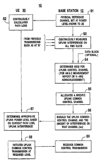
[0016] BRIEF DESCRIPTION OF THE DRAWING(S)
[0017] Fig. 1A is a simplified block diagram of a base station of the present
invention.
-3b-
CA 02447496 2003-11-14
WO 02/093952 PCT/US02/15066
[0018] Fig. 1B is a simplified block diagram of a user equipment of the
present
invention.
[0019] Fig. 1 C is a simplified block diagram of an alternative embodiment of
a base
station of the present invention.
[0020] Fig. 2 is a simplified block diagram illustrating one preferred
embodiment of
the process of the common control channel uplink power control of the present
invention.
[0021] Fig. 3 is a flow diagram showing an alternative embodiment of the
present
invention.
[0022] DETAILED DESCRIPTION OF THE PREFERRED EMBODIMENT(S)
[0023] The present invention will be described with reference to the drawing
figures
wherein like numerals represent like elements throughout.
[0024] Fig. 1A is a simplified block diagram of a universal mobile
telecommunications
system terrestrial radio access network (UTRAN) base station 12, (hereinafter
BS 12),
which communicates wirelessly over an RF link 25 to a UE 30, (shown in Fig.
1B).
The UE 30 may be a wireless cell phone, PDA or other like device which may
include
additional capabilities such as paging, e-mail and the like.
[0025] The BS 12 comprises an antenna 24, (or multiple antennas), an
isolator/switch
22 (or like device), a time slot interference measurement device 26, an uplink
common
control channel receiver 28, a common control channel quality monitoring
device 18,
a summing device 20 and a reference downlink channel spreading and modulation
device 14. The BS 12 receives communications over the radio link 25 via the
antenna
24. Received signals are coupled to the interference measurement device 26 and
the
uplink common control channel receiver 28 through the isolator/switch 22.
[0026] The interference measurement device 26 measures time slot interference
on the
uplink common control channel. For example, the interference measurement
device
26 may measure interference signal code power (ISCP). The interference
-4-
CA 02447496 2003-11-14
WO 02/093952 PCT/US02/15066
measurement device 26 provides an output (Icc), which is an indicator of the
amount
of interference on the uplink common control channel.
[0027] The receiver 28, which maybe a matched filter, RAKE or like device,
receives
and applies the signal in the uplink common control channel to the channel
quality
(CQ) measuring device 18 for monitoring the channel control (CQ) of the uplink
common control channel and providing a quality margin (QM) for a given UE.
[0028] The QM can be signaled, for example, as a calculated Signal to
Interference
Ratio target (SIRta get) that the UE transmissions are expected to achieve.
The QM can
also be based upon a combination of factors including the SIRtarget, RF
propogation
conditions and/or the QoS requirements for the service desired by the UE 30.
In turn,
the SlRtarget may be based upon measurements from previous transmission from
the
particular UE, such as the block error rate (BLER). Unlike the uplink
interference
level, the QM is not required for each individual uplink common control
allocation
and can, as one option, be separately specified by the BS 12 or even
eliminated, as
shown in Figure 1 C.
[0029] Referring back to IA, when not specified by the BS 12 or when not
constantly
updated by the UE 30, the QM maybe stored and the most recent QM is used.
[0030] The Icc and QM values are applied to first and second inputs of the
summing
device 20. The output of the summing device 20 is input to the spreading and
modulation device 14. Although, the QM and the Icc may be combined by the
summing device 20 as shown, they may also be encoded into a single parameter,
further reducing downlink signaling overhead. As further alternative, the Icc
maybe
signaled separately, for example, on a broadcast channel. In that case, only
the QM
will need to be signaled. The Icc and QM, if not combined or encoded into a
single
parameter, may be separately input into the spreading and modulation device 14
and
sent over separate downlink channels. The output from the spreading and
modulation
device 14 is passed to the antenna 24 through the isolator/switch 22 for
transmission
to the UE 30. The QM and Icc are signaled over one or more downlink control
-5-
CA 02447496 2003-11-14
WO 02/093952 PCT/US02/15066
channels. The path loss measurement, (which is performed by the UE 30 as will
be
explained in further detail hereinafter), is performed on the reference
channel.
[0031 ] As shown, Figs. 1 A-1 C refer to reference channels (and control
channel(s)). It
should be noted that the present invention comprises only a portion of the
signaling
that is performed between the base station 12 and the UE 30. It is not central
to the
present invention whether the measurements described herein are sent over a
single
reference channel, a single control channel or multiple reference and/or
control
channels. It is contemplated that a combination of reference and/or control
channels
maybe used within the spirit and scope of the present invention.
[0032] Referring to Fig. 1B, the UE 30 comprises an antenna 32, an
isolator/switch 34,
a reference channel receiver 36, a path loss calculation device 42, power
level
calculation device 44, an adaptive modulation and coding controller (not
shown), a
signaling receiver 48 and a power amplifier 50. The antenna 32 receives
communications from the BS 12 over the RF link 25 and applies the
communications
through the isolator/switch 34, as appropriate to either the reference channel
receiver
36 (i.e., the reference channel(s)), or the signaling receiver 48 (i.e., the
control
channel(s)).
[0033] The reference channel receiver 36, receives and processes one or more
reference channels in a manner that is well known to those of skill in the
art.
Accordingly, such detail will not be included herein. The reference channel
receiver
36 performs an estimate of the reference channel for data detection and
provides the
power level of the received signal to the path loss calculation device 42. The
path loss
calculation device 42 employs the power level to determine power loss in the
downlink transmission.
[0034] The QM and Icc information transmitted by the BS 12 are received by the
signaling receiver 48, which passes this information to the power level
calculation
device 44. The power level calculation device 44 uses the outputs of the path
loss
calculation device 42 and the signaling receiver 48 to determine a proper
power level
for transmission to BS 12 as a function of path loss and interference in the
RF link 25.
-6-
CA 02447496 2003-11-14
WO 02/093952 PCT/US02/15066
[0035] The output 44a of the power level calculation device 44 regulates the
output
power of the UE 10 via control of the power amplifier 50. The power amplifier
50
amplifies, as appropriate.
[0036] The output of the amplifier 50 is transmitted to the BS 12 through the
isolator/switch 34 and the antenna 32.
[0037] As those of skill in the art would understand, TDD utilizes a
transmission
structure whereby a frame is repetitively transmitted, each frame comprising a
plurality
of time slots. Data to be transmitted is segmented, and the segmented data is
then
scheduled for transmission in one or more time slots. For TDD, the CQ
interference
measurement from the same slot in a previous frame is very valuable in
determining
the modulation and coding rate of the current frame. As will be described in
greater
detail hereinafter, the CQ interference measurement as measured at the BS 12
is
signaled in the downlink in advance of the common control uplink transmission.
[0038] One embodiment of the method 10 of the present invention is shown in
the
flow diagram of Fig. 2. In this method, the BS 12, at step S 1, the reference
channel is
transmitted, with a power level known to the UE 30. The UE 30 continuously
calculates path loss at step S2. The BS 12 continuously measures uplink
interference
on all time slots, at step S3, based on transmissions from the UEs, (only one
UE 30
being shown in Fig. 2 for simplicity); and can also be based upon transmission
from
other base stations, (only one BS 12 shown for simplicity).
[0039] The BS 12, at step S4, determines the need for an uplink common control
channel, for example: 1) an AM&C measurement report; or 2) Hybrid-Automatic
Repeat Request (H-ARQ) control information. This determination may
optionallybe
in response to the receipt of a data block. At step S5, the BS 12 allocates a
specific
uplink common control channel, indicating the uplink interference level Icc in
that
time slot. The BS 12 at step S6 signals the uplink common control channel to
be
utilized and the uplink interference level (Icc) for the allocated channel.
These
parameters are signaled over a downlink control channel. Note that the
parameters of
the specific uplink control channel may be implicitly known.
-7-
CA 02447496 2003-11-14
WO 02/093952 PCT/US02/15066
[0040] The UE 30, at step S7, determines the appropriate uplink power level
for
transmission to the BS 12 based upon the current path loss measured by the UE
30 at
step S2 and the interference level Ice obtained from the BS 12.
[0041 ] As stated hereinbefore, in an alternative embodiment the QM may also
be
signaled along with, or separate from, the interference level Icc. This
alternative
embodiment of the method 20 of the present invention is shown in Fig. 3,
providing
further optimization of the uplink common control channel power level. Those
steps in
Fig. 3 that are numbered the same as Fig. 2 implement the same steps of the
procedure.
However, further optimization is achieved by additionally signaling a
requested QM
with the uplink common control channel allocation. The QM is based, among
other
aspects, upon previous transmissions from the particular UE received at step
S3. Fig.
3 shows step S6 modified as step S6A and step S7 modified as step S7A. As
shown in
both Figs. 2 and 3, the BS 12 may perform step S4 in response to receiving a
data
block; or may be independent of whether or not a data block is received.
[0042] Referring back to Fig. 2, the transmit power level of a UE (Tue) may be
represented by the following equation:
TuE = PL+Icc Equation (1)
where PL is the path loss; and Icc is the interference level for an uplink
common
control channel communication. The path loss (PL) may be calculated as
follows:
PL=TREF -RuE Equation (2)
where TREF is the power of the reference signal at the BS 12 and RUE is the
received
power at the UE 30 of the reference signal.
[0043] The UE 30 at step S8, initiates an uplink common control transmission
at the
uplink transmit power level calculated using Equations 1 and 2; the
transmission being
received by the BS 12, at step S9.
[0044] When the QM is transmitted from the BS 12 to the UE 30 as shown in the
alternative method 20 of Fig. 3, the transmit power level of a UE (TUE) may be
represented by the following equation:
TU = PL+QM+Icc Equation (3)
-8-
CA 02447496 2003-11-14
WO 02/093952 PCT/US02/15066
where PL is the path loss; QM is the desired quality margin and Icc is the
interference
level for the uplink common control channel communication. The path loss (PL)
may
be calculated as follows:
PL=TpF -RUE Equation (4)
where TREF is the power of the reference signal at the BS 12 and R is the
received
power of the reference signal at the UE.
[0045] The present invention has several advantages over prior art methods.
The
measured uplink interference level can be specified in the allocation message,
assuring
a very low latency uplink interference measurement is available to the UE.
Alternatively, the measured uplink interference level can be provided via the
downlink
common control channel or other means. Since the AM&C uplink control channel
is
expected to exist in a single 3G TDD mode timeslot, still further efficiencies
are
perceived. Normally, in slotted systems employing similar open loop power
control
mechanisms, interference must be reported for each slot for proper operation.
Since
only one slot is used for the uplink common control channel and therefore only
the
uplink interference for one slot has to be signaled, minimal overhead is
introduced to
the downlink allocation signaling for the benefit of more efficient use of
uplink radio
resources.
[0046] While the present invention has been described in terms of the
preferred
embodiment, other variations which are within the scope of the invention as
outlined
in the claims below will be apparent to those skilled in the art.
-9-