Note : Les descriptions sont présentées dans la langue officielle dans laquelle elles ont été soumises.
CA 02447747 2006-08-02
CUTTING ELEMENT HAVING ENHANCED CUTTING GEOMETRY
(0001] The invention relates generally to roller cone drill bits for drilling
earth
formations, and more specifically to the geometry of cutting elements on
roller
cone drill bits.
[0002] FIG. 1 shows one example of a roller cone drill bit used in a
conventional
drilling system for drilling a well bore in an earth formation. The drilling
system
includes a drilling rig 100 used to turn a drill string 120 which extends
downward
into a well bore 140. Connected to the end of the drill string 120 is roller
cone-
type drill bit 200.
[0003] In roller cone bits, the cutting elements drill the earth formation by
a
combination of compressive fracturing and shearing action. Prior art milled
tooth
bits typically have teeth formed from steel or other easily machinable high-
strength material, to which a hardface overlay such as tungsten carbide or
other
wear resistant material is often applied. The hardfacing is applied by any one
of a
number of well known methods. There are a number of references which describe
specialized exterior surface shapes for the substrate.
(0004] The specialized shapes are intended to provide a cutting structure
which
includes more thickness of hardface overlay in wear-prone areas, so that the
useful
1
CA 02447747 2003-11-03
life of the teeth can be increased. Examples of such specialized substrate
shapes
are shown in U.S. Patent Nos. 5,791,423, 5,351,771, 5,351,769, and 5,152,194,
for
example. These references show that the teeth have substantially regular
trapezoidal exterior hardface surfaces. The irregular shape of the substrate
outer
surface is selected to provide additional hardface in the wear prone areas
while
maintaining a conventional exterior tooth surface.
[0005] U.S. Patent No. 6,029,759 issued to Sue et al shows a milled tooth
drill bit
having teeth in a gage row (the outermost row of teeth on any cone used to
maintain full drilling diameter), wherein the teeth have a particular outer
surface.
See for example Figure 12B in Sue et al '759. The particular outer surface of
these teeth is intended to make it easier to apply hardfacing in two layers,
using
two different materials. The purpose of such tooth structures is to have
selected
hardfacing materials positioned to correspond to the level of expected wear on
the
various positions about the outer surface of the tooth.
(0006) Polycrystalline diamond ("PCD") enhanced inserts and tungsten carbide
("WC-Co") inserts are two commonly used inserts for roller cone rock bits and
hammer bits. A roller cone rock bit typically includes a bit body adapted to
be
coupled to a rotatable drill string and include at least one "cone" that is
rotatably
mounted to the bit body. The cone typically has a plurality of inserts pressed
into
it. The inserts contact with the formation during drilling.
[0007] The PCD layer on PCD enhanced inserts is extremely hard. As a result,
the
PCD layer has excellent wear resistance properties. While the actual hardness
of
the PCD layer varies for the inserts used in particular bit types, each type
of PCD
has a common failure mode of chipping and spelling due to cyclical impact
loading on the inserts during drilling. Conversely, the softer, tougher
tungsten
carbide inserts tend to fail by excessive wear and not by chipping and
spelling.
2
CA 02447747 2006-08-02
Therefore a need exists for inserts for roller cone bits that are optimized
for
resisting both wear and impact as encountered during drilling.
[0008] In one aspect, the present invention relates to a drill bit that
includes a bit
body, at least one roller cone attached to the bit body and able to rotate
with
respect to the bit body, and a plurality of cutting elements disposed on the
at least
one roller cone, at least one of the plurality of cutting elements comprising
a first
area defining a trailing edge, and a second area proximate the first area
defining a
main wear surface, wherein, in a preferred embodiment, a surface of the second
area is a curved surface having a radius of curvature substantially equal to a
radius
of a borehole.
[0009] In another aspect, the present invention relates to a drill bit that
includes a
bit body, at least one roller cone attached to the bit body and able to rotate
with
respect to the bit body, and a plurality of cutting elements disposed on the
at least
one roller cone, at least one of the plurality of cutting elements comprising
a first
area defining a trailing edge, a second area proximate the first area defining
a main
wear surface, a third area defining a spherical cutting surface that interacts
with a
hole bottom, and a transition zone, wherein the transition zone is disposed
between
the first, second, and third areas.
(0010] In another aspect, the present invention relates to an insert for a
drill bit that
includes a contact portion adapted to contact an earth formation, the contact
portion further comprising a first area defining a relieved trailing edge, and
a
second area defining a main wear surface, wherein a surface of the second area
is a
curved surface having a radius of curvature substantially equal to a radius of
a
borehole.
3
CA 02447747 2006-08-02
[0010.1] According to another aspect of the present invention there is
provided a
drill bit, comprising: a bit body; at least one roller cone attached to the
bit
body and able to rotate with respect to the bit body; and a plurality of
cutting
elements disposed on the at least one roller cone, at least one of the
plurality
of cutting elements comprising: a barrel axis; a first area defining a
secondary
wear surface, wherein the first area is formed as a convex surface on a
trailing
edge of the at least one cutting element; a second area proximate the first
area
and defining a main wear surface, wherein the second area is formed as a
convex curved surface having a radius of curvature substantially equal to a
radius of a borehole; a third area defining a spherical cutting surface; and a
non-spherical transition zone disposed between the third area and the first
and
second areas, wherein the barrel axis intersects the transition zone.
[0010.2] According to a further aspect of the present invention there is
provided a
drill bit, comprising: a bit body; at least one roller cone attached to the
bit
body and able to rotate with respect to the bit body; and at least one gage
insert attached to the roller cone and comprising a barrel axis and contact
portion adapted to contact an earth formation, the contact portion comprising:
a first area defining a relieved trailing edge; a second area defining a main
wear surface formed proximate to the first area, wherein the second area is a
convex curved surface having a radius of curvature substantially equal to a
radius of a borehole; a third area defining a spherical cutting surface; and a
transition zone defining a wedge-shaped surface formed between the third area
and the first and second areas, wherein the barrel axis intersects the wedge-
shaped surface of the transition zone.
[0010.3] According to another aspect of the present invention there is
provided an
insert for a drill bit comprising: a barrel axis; and a contact portion
adapted to
contact an earth formation, the contact portion comprising: a first area
defining a relieved trailing edge; a second area proximate to the first area
and
3a
CA 02447747 2006-08-02
defining a main wear surface, wherein a surface of the second area is a convex
curved surface having a radius of curvature substantially equal to a radius of
a
borehole; a third area defining a spherical cutting surface; and a non-
spherical
transition zone disposed between the third area and the first and second
areas,
wherein the transition zone intersects the barrel axis.
3b
CA 02447747 2003-11-03
[0011] Other aspects and advantages of the invention will be apparent from the
following description and the appended claims.
Brief Description of Drawings
[0012] Figure 1 shows a schematic diagram of a drilling system for drilling
earth
formations having a drill string attached at one end to a roller cone drill
bit.
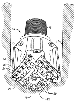
[0013] Figure 2 shows a roller cone bit having inserts in accordance with an
embodiment of the present invention.
[0014] Figure 3 shows an exploded view of an insert formed in accordance with
an
embodiment of the present invention.
[0015] Figures 4a-4d show various side and top views of an insert formed in
accordance with an embodiment of the present invention.
[0016) Figure 5 shows inserts designed in accordance with one embodiment of
the
present invention disposed on a gage row.
Detailed Description
(0017] The present invention relates to an improved geometry for cutting
elements
used in roller cone drill bits. In particular, certain embodiments relate to
an insert
having an optimized shape for rotary drilling mechanics. As used herein, the
term
"cutting element," is used to generically refer to different types of teeth
used on
bits (e.g., milled teeth and inserts).
[0018] Referring to Figure 2, a roller cone rock bit 10 according to the
preferred
roller cone bit embodiment of the present invention, is shown disposed in a
borehole 11. The bit 10 has a body 12 with legs 14 extending generally
downward, and a threaded pin end 15 opposite thereto for attachment to a drill
string (not shown). Journal shafts 16 are cantilevered from legs 14. Rolling
4
CA 02447747 2003-11-03
cutters (or roller cones) 18 are rotatably mounted on the journal shafts 16.
Each
cutter 18 has a plurality of inserts 20 mounted thereon.
[0019] As the body 12 is rotated by rotation of the drill string (not shown),
the
cutters 18 rotate over the borehole bottom 22 and maintain the gage of the
borehole by rotating against a portion of the borehole sidewall 24. As the
cutter
18 rotates, individual inserts are rotated into contact with the formation and
then
out of contact with the formation. As a result, the inserts undergo cyclical
loading
which can contribute to fatigue failure. Inserts 26 are called "gage" inserts
because they contact, at least partially, the sidewall 24 to maintain the gage
of the
borehole 11. All of the inserts, and particularly gage inserts 26, undergo
repeated
impact loading as they are rotated into and out of contact with the earth
formation.
In the present invention, at least one insert on the roller cone rock bit 10
has an
improved cutting structure, as described below.
[0020] In different embodiments, inserts designed in accordance with the
present
invention may comprise a composite PCD material. Preferably for a roller cone
bit application, the insert has a hardness of between about 1000 to 3000
Vickers
Hardness Units (HV). This hardness provides a resulting increase in impact
resistance that is beneficial for inserts used in roller cone drill bits,
while not
significantly sacrificing wear resistance. However, inserts having hardnesses
well
outside this range may be used.
[0021] In other embodiments, inserts designed in accordance with the present
invention may comprise tungsten carbide inserts. One of ordinary skill in the
art
will recognize that the type of insert material is not as significant as the
improved
geometries of the insert, described below. Accordingly, it is expressly within
the
scope of the present invention that various compositions (be it boron-nitride
containing, tungsten-carbide containing, PCD, etc. inserts) may be used with
the
below described geometry.
CA 02447747 2003-11-03
[0022] Referring to Figures 3 and 4a-4d, one embodiment of an insert 50
according to the present invention is shown. The insert 50 may be used as any
one
of the inserts on a cutter but has particular application as a gage insert.
Accordingly, the following description is made in reference to insert 50 being
a
gage insert. Insert 50 comprises a substrate having a grip portion 40 and an
extension portion 42. The grip portion 40 is sized for a press fit within
sockets
formed in rolling cutters (18 in Figure 2). The extension portion has a outer
layer
(not shown) that contacts the borehole (not shown), which is referred to as
the
contact surface (not separately numbered). In this particular embodiment, the
contact surface comprises first, second, and third "enhanced" areas that
improve
the rate of penetration and/or the life of the insert.
[0023] The first area 52 comprises a convex relief located on the trailing
edge of
the insert 50. This first area 52 acts as a secondary wear surface and is used
to
reduce the wear rate as well as heat generation due to the insert 50 dragging
on the
bore sidewall as it exits the formation. By removing material from the
trailing
edge on the insert 50 (to form the first area 52), a relieved surface is
formed and
therefore, eliminates what would otherwise be an unsupported extension that
could
lead to insert breakage. Thus the relief area reduces the stress on the
trailing side
of the insert as it exits the hole wall in a sheering motion.
[0024] The second area 54 acts as a main wear surface for the insert 50. This
main
wear surface is important to reduce the rate at which the insert wears or
erodes
away. Notably, the second area 54 is not flat, but rather, in the preferred
embodiment, has a large radius (L) similar to that of the hole being drilled,
in
order to increase the surface area of the insert that makes contact with the
bore
wall. One of ordinary skill in the art will appreciate that depending on the
size of
the bit, drill string, insert, etc., the size of the radius L will vary.
However, the
actual size of the radius is not significant, instead, in the preferred
embodiment,
6
CA 02447747 2003-11-03
providing a radius of curvature approximate to the radius of the borehole is
the
significant step.
[0025] As noted above, in the preferred embodiment, the insert has a radius of
curvature substantially similar to the radius of the borehole being drilled.
However, it is expressly within the scope of the present invention that the
radii can
vary by as much as 100%. Further, while the main wear surface has been
described as a convex surface, in some embodiments, the main wear surface is a
planar surface.
[0026] By providing a convex surface having a relatively large diameter, the
second area 54 distributes wear over a larger area of the insert, decreasing
the
amount of wear that any one particular portion of the insert is subjected to.
Furthermore, decreasing stress on the insert results in a decreased chance of
insert
breakage.
[0027] Furthermore, in certain embodiments, a third area 56 is disposed on the
insert 50. In a preferred embodiment, the third area 56 is a spherical cutting
surface adapted to penetrate the hole bottom. Accordingly, while the first and
second areas (52 and 54, respectively), are scraping the hole sidewall, the
third
area 56 is scraping the hole bottom, and removing formation. A transition zone
58, located between the third area 56 and the first and second areas (52,54)
is
significant because it forms a wedge shape. This wedge shape (formed from the
geometry of the three areas) helps to increase the size of rock fracture. In a
preferred embodiment, the transition zone 58 is slightly bowed outward in
order to
maximize carbide volume and reduce insert stress.
[0028] This wedge shape, located, in this embodiment, between the third
surface
and the other two enhanced surfaces, represents a significant improvement over
typical prior art inserts. In particular, embodiments of the present invention
provide the wedge shape in a plane nearly perpendicular to the insert barrel
axis.
7
CA 02447747 2003-11-03
Typical chisel inserts have a wedge shape in a plane that passes through the
axis of
the insert barrel. It has been discovered that additional advantages, such as
those
described above, result from the geometry of the present invention. While the
"wedge-shaped" transition zone has been described in reference to an
embodiment
where three enhanced surfaces are present, the transition zone may be used in
embodiments having more or less.
[0029) What is significant, however, is the overall shape and relative
orientation of
the transition zone. As described above, preferably, the transition zone has
an
overall wedge shape and is disposed such that the wedge is perpendicular to a
barrel axis of the chisel. One of ordinary skill in the art, having reference
to this
disclosure, would understand the variations that fall within this general
description.
[0030] Figure S shows one embodiment of inserts designed in accordance with
embodiments of the present interacting with a borehole 70. In Figure 5, a gage
insert 72, is shown contacting a sidewall (not separately numbered) of the
borehole 70. From this figure, the interaction of the insert 72 with the
sidewall 70
may be understood. Further, while this figure shows enhanced geometry inserts
disposed on a gage row of a roller cone, it is expressly within the scope of
the
present invention that cutting elements (whether insert or milled tooth)
having the
improved geometry may be disposed in any fashion on the roller cone or cones.
[0031] Further, Figure 5 shows transition zone 58 contacting the borehole 70.
From this figure, the overall "wedge-shape" of the transition zone 58 is
clearly
seen. As shown in this embodiment, the transition zone 58 is disposed such
that
the transition zone 58 is in a plane substantially perpendicular to a barrel
axis of
the gage insert 72. This is a distinct difference as compared with prior art
inserts,
which have "wedge-shaped" portions clisposed in a plane substantially parallel
to
the barrel axis of the gage insert.
8
CA 02447747 2003-11-03
[0032] It should also be clearly understood that while the invention is
described
herein with reference to bits having cutting elements which are inserts made
from
hard material, such as tungsten carbide, and/or superhard material, such as
diamond or cubic boron nitride, the shape of the exterior surface of selected
cutting elements on a drill bit according to the invention is not limited to
insert
bits. Other roller cone bits known in the art, including those having cutting
elements which are made from milled teeth having a hardfacing layer disposed
thereon, are also within the scope of this invention.
[0033] It should also be noted that while the embodiments of the invention
shown
herein are described as being used with a bit having three roller cones,
embodiments of the invention may include drill bits having any number of
roller
cones.
[0034] In one or more embodiments of the present invention, a cutting element
in
accordance with embodiments of the present invention advantageously provides
an improved rate of penetration, reduction of wear, and/or increases the
amount of
formation cut with each rotation of the cone. Moreover, in one more
embodiments
having three areas, as discussed above, the resultant wedge shape formed
between
the three areas increases the amount of rock fractured as compared to the
prior art.
In addition, because of the reduced stresses on the insert, harder carbide
grades
may be used.
[0035] The use of these harder grades of tungsten carbide further slows the
insert
wear rate. Accordingly, it is expressly within the scope of the present
invention
that any hardness range may be used. One of ordinary skill in the art, having
reference to this disclosure, will recognize that the various properties of an
insert
in accordance with the present invention may be tailored, depending on the
particular formation being drilled.
9
CA 02447747 2003-11-03
(0036] While the invention has been described with respect to a limited number
of
embodiments, those skilled in the art, having benefit of this disclosure, will
appreciate that other embodiments can be devised which do not depart from the
scope of the invention as disclosed herein. Accordingly, the scope of the
invention should be limited only by the attached claims.