Sélection de la langue

Search

Sommaire du brevet 2449596 

Énoncé de désistement de responsabilité concernant l'information provenant de tiers

Une partie des informations de ce site Web a été fournie par des sources externes. Le gouvernement du Canada n'assume aucune responsabilité concernant la précision, l'actualité ou la fiabilité des informations fournies par les sources externes. Les utilisateurs qui désirent employer cette information devraient consulter directement la source des informations. Le contenu fourni par les sources externes n'est pas assujetti aux exigences sur les langues officielles, la protection des renseignements personnels et l'accessibilité.

Disponibilité de l'Abrégé et des Revendications

L'apparition de différences dans le texte et l'image des Revendications et de l'Abrégé dépend du moment auquel le document est publié. Les textes des Revendications et de l'Abrégé sont affichés :

  • lorsque la demande peut être examinée par le public;
  • lorsque le brevet est émis (délivrance).
(12) Demande de brevet: (11) CA 2449596
(54) Titre français: SYSTEME DE CABLAGE DIELECTRIQUE POUR MICRO-ONDES MILLIMETRIQUES
(54) Titre anglais: DIELECTRIC CABLE SYSTEM FOR MILLIMETER MICROWAVE
Statut: Morte
Données bibliographiques
Abrégés

Abrégé anglais


The subject of the invention is a cable-like device called "FiberGuide" that
conducts
millimeter wave energy from one place to another in a manner similar to a
fiber optics
cable, with the shield and spacing to ensure the lowest possible loss, plus
the methods
of interfacing of the said cable-like device to each other as well as to
traditional
microwave structures such as metallic resonating cavities and metallic
waveguides.

Revendications

Note : Les revendications sont présentées dans la langue officielle dans laquelle elles ont été soumises.


CLAIMS

I Claim:

1. A device composed in the shape of wire made out of plastic material that
acts as a dielectric waveguide for millimeter microwave electromagnetic
radiation
2. The device of claim 1 wherein the wire has circular, eliptical or
rectangular
cross-section.
3. The device of claim 1 and 2 wherein the plastic wire is surrounded by a
insulating foam that has lower dielectric constant than the wire of claim 1.
4. The device of claim 1,2 and 3 that is shielded by an outer sleeve made out
of
a material harder than the foam of claim 3.
5. The device of claim 1, 2, 3 and 4 wherein the shield of claim 4 may be a
composite material that is transparent, absorbing or reflective to microwaves.

Description

Note : Les descriptions sont présentées dans la langue officielle dans laquelle elles ont été soumises.


CA 02449596 2003-12-05
Dielectric Cable System For Millimeter Microwave
DESCRIPTION
Introduction
Issue of the optimal method of transmitting energy from one place to another
with
the highest possible efficiency and the lowest possible losses is encountered
in
every area of engineering in practically every application dealing with
electrical,
electromagnetic or acoustic forms of energy. Such optimal solutions are very
different at each of the spectral range. At low frequency of electromagnetic
energy, when it is referred to as electrical energy we transmit power through
electrical cables consisting of two isolated conductors (single phase AC, or
DC)
or more conductors (3 or more phase AC). In the domain of high frequency
signals, typically 1 OOkHz-1 GHz the optimal choice of a cable is coaxial
cable
consisting of a center conductor surrounded by a dielectric insulator and
surrounded by a conductive shield, or a twisted pair cable similar to the one
for
low frequency AC power but with controlled impedance and low-loss dielectric
insulation. Beyond about SGHz up to about 30GHz the optimal, the least lossy
and most convenient way of transmitting microwave energy are metalic
waveguides. Beyond 30GHz however, metallic waveguides are becomming
increasing lossy which makes it difficult to transmit microwave power over
large
distances. At those frequency, in the so-called millimeter microwave range
such
waveguides are limited in practical applications to about couple of meters
distance due to high losses. From millimeter microwave up to the optical range
of electromagnetic energy, dielectric waveguidesloptic fibers become the most
optimal way of energy transmission.
Explanation of terms:
Waveguide: tubular circular or rectangular in cross section hollow structure
made
of conductive material (e.g. metal), that conducts electromagnetic energy
along
its length and inside it.
Dielectric Waveguide: tubular circular or rectangular in cross section solid
structure that conducts electromagnetic energy along its length inside and in
the
immediate vicinity outside of it.
Fiber Optic Cable: Dielectric Waveguide applied in the optical range.
"FiberGuide": dielectric waveguide in foam isolation that is used for
cinducting
millimeter microwave energy; the subject of this patent.
Coupler: mechanical device that allows joining two waveguides (dielctric
waveguide to dielectric waveguide or dielectric waveguide to metal waveguide)
together such that the energy transmission is unhidered.


CA 02449596 2003-12-05
EMBODIMENT OF THE INVENTION
In this embodiment, designed to transmit millimeter microwave at 70-90GHz,
dielectric waveguide consists of a polipropylene or PTFE cable/wire with
diameter of about 2mm (see FIG.1 ) surrounded by air filled foam that has a
very
low dielectric constant, and made out of material of very low dielectric
losses at
those frequency. The material of choice is polypropylene or PTFE. The whole
structure is surrounded by a metallic or metallized (from the inside} shield
or a
sleeve. A material of choice would be silver or aluminum coated polyester
foils
underneath PVC jacket, or copper foil underneath a PVC or PTFE jacket .
An alternative cross section (to circular) for the center waveguide is
rectangular
with approx 2:1 aspect ratio, to allow retaining the definite polarization
plane of
the transmitted wave.
Coupler for joining two dielectric cables together.
The couple consists of a plastic pipe a few cm long, threaded inside from both
ends, see FIG.2. Inner diameter of the pipe is a fraction of millimeter
smaller
than the outer diameter of the Dielectric Cable outer sleeve. One end is
threaded with a right-hand-side thread, the other left-hand side such, that
when
the dielectric cable is pushed from both end, both ends of the cables may be
screwed in simultaneously by turning the pipe, until both open sections of the
cables will meet in the middle. Since the millemeter microwave fit is tolerant
to
within quarter-wavelength, that is about 1 mm in this case, the fit need not
be as
tight and precise as in case of optical fiber junction. In this particular
example a
0.5 or even 1 mm gap may be tolerable.
RESULTS OF PROTOTYPE TESTING
[To be included]
Conclusions:
The laboratory tests prove the concept and demonstrate that it works
2
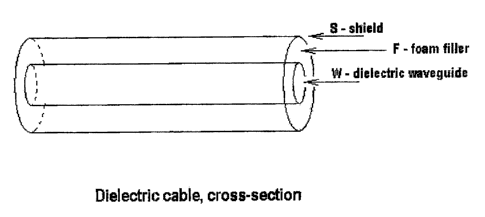
Dessin représentatif
Une figure unique qui représente un dessin illustrant l'invention.
États administratifs

Pour une meilleure compréhension de l'état de la demande ou brevet qui figure sur cette page, la rubrique Mise en garde , et les descriptions de Brevet , États administratifs , Taxes périodiques et Historique des paiements devraient être consultées.

États administratifs

Titre Date
Date de délivrance prévu Non disponible
(22) Dépôt 2003-12-05
(41) Mise à la disponibilité du public 2005-06-05
Demande morte 2009-12-07

Historique d'abandonnement

Date d'abandonnement Raison Reinstatement Date
2008-12-05 Absence de requête d'examen
2009-12-07 Taxe périodique sur la demande impayée

Historique des paiements

Type de taxes Anniversaire Échéance Montant payé Date payée
Le dépôt d'une demande de brevet 150,00 $ 2003-12-05
Taxe de maintien en état - Demande - nouvelle loi 2 2005-12-05 50,00 $ 2005-11-21
Taxe de maintien en état - Demande - nouvelle loi 3 2006-12-05 50,00 $ 2006-10-27
Taxe de maintien en état - Demande - nouvelle loi 4 2007-12-05 50,00 $ 2007-09-21
Taxe de maintien en état - Demande - nouvelle loi 5 2008-12-05 100,00 $ 2008-11-25
Titulaires au dossier

Les titulaires actuels et antérieures au dossier sont affichés en ordre alphabétique.

Titulaires actuels au dossier
BLESZYNSKI, STANISLAW
Titulaires antérieures au dossier
S.O.
Les propriétaires antérieurs qui ne figurent pas dans la liste des « Propriétaires au dossier » apparaîtront dans d'autres documents au dossier.
Documents

Pour visionner les fichiers sélectionnés, entrer le code reCAPTCHA :


Pour visualiser une image, cliquer sur un lien dans la colonne description du document. Pour télécharger l'image (les images), cliquer l'une ou plusieurs cases à cocher dans la première colonne et ensuite cliquer sur le bouton "Télécharger sélection en format PDF (archive Zip)" ou le bouton "Télécharger sélection (en un fichier PDF fusionné)".

Liste des documents de brevet publiés et non publiés sur la BDBC .

Si vous avez des difficultés à accéder au contenu, veuillez communiquer avec le Centre de services à la clientèle au 1-866-997-1936, ou envoyer un courriel au Centre de service à la clientèle de l'OPIC.


Description du
Document 
Date
(yyyy-mm-dd) 
Nombre de pages   Taille de l'image (Ko) 
Abrégé 2003-12-05 1 19
Description 2003-12-05 2 126
Dessins représentatifs 2004-01-15 1 6
Dessins 2003-12-05 1 12
Revendications 2003-12-05 1 25
Page couverture 2005-05-11 1 29
Cession 2003-12-05 2 102
Correspondance 2003-12-30 1 10
Taxes 2005-11-21 1 25
Correspondance 2007-09-21 1 27
Taxes 2007-09-21 1 45