Sélection de la langue

Search

Sommaire du brevet 2451337 

Énoncé de désistement de responsabilité concernant l'information provenant de tiers

Une partie des informations de ce site Web a été fournie par des sources externes. Le gouvernement du Canada n'assume aucune responsabilité concernant la précision, l'actualité ou la fiabilité des informations fournies par les sources externes. Les utilisateurs qui désirent employer cette information devraient consulter directement la source des informations. Le contenu fourni par les sources externes n'est pas assujetti aux exigences sur les langues officielles, la protection des renseignements personnels et l'accessibilité.

Disponibilité de l'Abrégé et des Revendications

L'apparition de différences dans le texte et l'image des Revendications et de l'Abrégé dépend du moment auquel le document est publié. Les textes des Revendications et de l'Abrégé sont affichés :

  • lorsque la demande peut être examinée par le public;
  • lorsque le brevet est émis (délivrance).
(12) Brevet: (11) CA 2451337
(54) Titre français: ROBINET A BILLE A EXTREMITE A BRIDE UNIQUE D'UNE STRUCTURE UNIFORME
(54) Titre anglais: SINGLE FLANGED END BALL VALVE OF UNITARY CONSTRUCTION
Statut: Périmé
Données bibliographiques
(51) Classification internationale des brevets (CIB):
  • F16K 5/06 (2006.01)
  • F16K 27/06 (2006.01)
(72) Inventeurs :
  • RECK, MICHAEL E. (Etats-Unis d'Amérique)
(73) Titulaires :
  • NIBCO INC. (Etats-Unis d'Amérique)
(71) Demandeurs :
  • WEBSTONE COMPANY, INC. (Etats-Unis d'Amérique)
(74) Agent: RIDOUT & MAYBEE LLP
(74) Co-agent:
(45) Délivré: 2008-05-13
(86) Date de dépôt PCT: 2002-06-10
(87) Mise à la disponibilité du public: 2003-01-03
Requête d'examen: 2003-12-19
Licence disponible: S.O.
(25) Langue des documents déposés: Anglais

Traité de coopération en matière de brevets (PCT): Oui
(86) Numéro de la demande PCT: PCT/US2002/018272
(87) Numéro de publication internationale PCT: WO2003/001092
(85) Entrée nationale: 2003-12-19

(30) Données de priorité de la demande:
Numéro de la demande Pays / territoire Date
60/300,345 Etats-Unis d'Amérique 2001-06-22
60/300,622 Etats-Unis d'Amérique 2001-06-25
10/097,762 Etats-Unis d'Amérique 2002-03-14

Abrégés

Abrégé français

L'invention concerne un robinet à bille (50) comportant une bride (78) servant de connexion avec un circulateur hydronique.


Abrégé anglais


A ball valve unit (50) includes a flange (78) for connecting to a hydronic
circulator.

Revendications

Note : Les revendications sont présentées dans la langue officielle dans laquelle elles ont été soumises.


CLAIMS:


1. A ball valve unit comprising:
a ball section, said ball section defining a stem chamber and a ball chamber,
said
stem chamber disposed adjacent to and extending outwardly from said ball
chamber;
a ball valve including a ball, said ball disposed completely within said ball
chamber;
a stem disposed within and extending outwardly from said stem chamber and
connected to said ball disposed within said ball chamber, an exposed portion
of said stem
extending beyond said stem chamber;
a handle connected to said exposed portion of said stem disposed within said
stem
chamber and connected to said ball, wherein actuation of said handle effects
actuation of
said ball for operating said ball valve unit;
a main section disposed separate from and adjacent to said ball section;
a drain valve communicating with said main section; and
a flange formed as a continuous portion of at least one of said main section
and said
ball section, said ball section including said stem chamber and said ball
chamber, wherein
said flange, said main section and said ball section including said stem
chamber and said
ball chamber being formed as a single piece formed of a rigid material.


2. The ball valve unit of claim 1, wherein said ball valve unit further
includes a
gasket disposed adjacent to said flange for forming a seal between said flange
and an
appliance.


3. The ball valve unit of claim 1, wherein said main section and said ball
section are made of brass.


4. The ball valve unit of claim 1, further including an end cap attached to at

least one of said main section and said ball section.


5. The ball valve unit of claim 4, wherein said main section and said end cap
are made of brass.


-9-


6. The ball valve unit of claim 1, wherein an outside surface of said flange
is
substantially flat.


7. The ball valve unit of claim 1, wherein said handle is wing-shaped.


8. The ball valve unit of claim 4, wherein an inner diameter of said chamber
is
substantially equal to an inner diameter of said end cap.


9. The ball valve unit of claim 1, wherein said drain valve is disposed
between
said flange and said ball valve.


-10-

Description

Note : Les descriptions sont présentées dans la langue officielle dans laquelle elles ont été soumises.


CA 02451337 2006-05-30

WO 03/001092 PCT/US02/18272
SINGLE FLANGED END BALL VALVE OF UNITARY CONSTRUCTION
BACKGROUND

This invention relates generally to ball valves, and more particularly to a
flanged end ball valve of unitary construction.

Traditionally, a ball valve is used in plumbing and heating applications to
shut off the flow of water or other fluid during replacement or repair of an
in-
line appliance or piece of equipment, such as a circulating pump. As shown in
Fig. 1, typically, a ball valve used in a plumbing and heating application
includes
a separate flange 2, a conventional ball valve 4, and a copper nipple 6 and
copper adapter 8 that connect the flange 2 to the conventional ball valve 4.
The
ball valve 4 is attached to the plumbing or heating system with copper tubing
10. The in-line appliance (not shown) is attached to the flange 2.
Alternatively,
an iron nipple 12 has been used to connect the flange 2 to the ball valve 4,
and
a copper adapter 14 has been used to connect the ball valve 4 to the copper
tubing 10, as shown in Fig. 2.

As shown in Figs. 1 and 2, in the conventional methods, there are several
potential leak paths. Also, there are areas of galvanic action between
dissimilar
metals. Further, installation of the flange, the nipples, and the adapters in
this
type of configuration is time consuming and expensive.


CA 02451337 2003-12-19
WO 03/001092 PCT/US02/18272
The conventional method shown in Fig. 3 includes an iron flange 16 that
includes a
screwdriver slot ball valve. The flange 16 is connected to a second iron
flange 18. A copper
adapter 20 connects the iron flange 18 to copper tubing 10. In this
configuration, since the
flange 18 is made of iron, there is an area of galvanic action between the
iron flange 18 and the

copper adapter 20. Also, there are several potential leak paths. Further, this
configuration is
complex, which increases the cost and installation time.

Fig. 4 shows another conventional configuration. This configuration includes
an iron
flange 30 connected to a copper tube 32 via a copper adapter 34. In this
conventional
configuration, it is not possible to isolate an in-line appliance, thereby
making repair and

replacement of the in-line appliance burdensome. Also, there are several
potential leak paths.
Further, there are areas of galvanic action between the copper adapter 34 and
the iron flange 30.
SUMMARY OF THE INVENTION

The present invention provides a ball valve unit that reduces the cost and
time required to
replace in-line appliances such as pumps.

The ball valve unit of the present invention also reduces the number of joints
and
flanges, thereby reducing the volume of the plumbing system and the number of
leakage paths.
Further, the present invention also provides a ball valve unit that prevents
the cracking of

brittle iron flanges and prevents galvanic action.

The present invention comprises a main section, a flange for connecting the
ball valve

unit to an appliance, wherein the flange is integrally formed with the main
section, a ball valve, a
chamber formed in the main section for accommodating the ball of the ball
valve, and a handle
for actuating the ball valve.

-2-


CA 02451337 2003-12-19
WO 03/001092 PCT/US02/18272
BRIEF DESCRIPTION OF THE DRAWINGS

The foregoing and other features and advantages of the present invention will
be more
fully understood from the following detailed description of illustrative
embodiments, taken in
conjunction with the accompanying drawings in which:

Fig. 1 shows a first conventional system.
Fig. 2 shows a second conventional system.
Fig. 3 shows a third conventional system.
Fig. 4 shows a fourth conventional system.

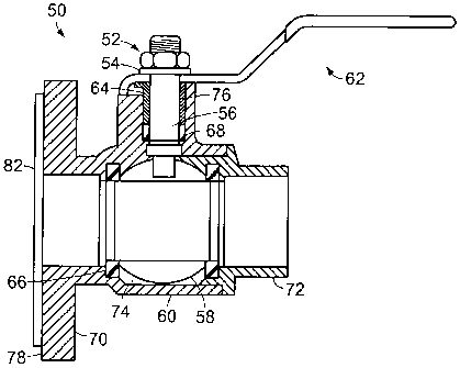
Figs. 5A and 5B show cross-sectional views of one embodiment of the ball valve
unit of
the present invention.

Figs. 6A and 6B show cross-section views of a second embodiment of the ball
valve unit
of the present invention.

Figs. 7A and 7B show a third embodiment of the ball valve unit of the present
invention.
Figs. 8A and 8B show a fourth embodiment of the ball valve unit of the present

invention.

Figs. 9A and 9B show a fifth embodiment of the ball valve unit of the present
invention.
Figs. 10A and l OB show a sixth embodiment of the ball valve unit of the
present
invention.

-3-


CA 02451337 2003-12-19
WO 03/001092 PCT/US02/18272
DETAILED DESCRIPTION OF THE INVENTION

Fig. 5A shows a cross-sectional view of one embodiment of the present
invention. As
shown in Fig. 5A, the single flanged ball valve unit, according to the present
invention, is
designated by reference number 50. It comprises a handle nut 52, a washer 54,
a stem 56, a ball

58, a body 60, a handle 62, a packing gland 64, seats 66, and a stem seal 68.
The body 60
comprises a main section 70 and an end cap 72. The main section 70 includes a
chamber 74
adapted to accommodate the ball 58 and seats 66, a stem hole 76 to receive the
stem 56 and stem
sea168, and a flange 78 to be positioned juxtaposed an inline appliance or
equipment, such as a
circulating pump (not shown). The ball valve unit 50, preferably, is 600 PSI
rated for use with

water, oil or gas. The inner diameter of the chamber 74 is substantially equal
to the inner
diameter of the end cap 72, thereby maximizing flow through the ball valve
unit. Fig. 5B shows
a side view of the flange 78.

The main section 70 and flange 78 are of unitary construction and preferably
made from
cast or hot forged brass. Since plumbing and heating systems typically
comprise brass or copper
tubing, this prevents the occurrence of electrolysis and galvanic action at
the junction of the ball

valve unit and the system tubing. Also, brass is a much softer alloy than
traditional iron used for
the flanges currently on the market that often crack when slightly over
tightened.

The ba1158 is preferably made of Brass/Hard Chrome Plate and fits between
seats 66,
preferably made from Teflon or PTFE. The ball 58 is actuated with a blow-out
proof stem 56
preferably made of Brass (ASTM B124-C37700). The ball 58 is actuated with a
handle 62,

preferably made of stamped steel with a vinyl coating.

The stem 56 is sealed with a stem sea168, preferably made from Teflon or
PTFE, and
an adjustable packing gland 64, preferably Brass (ASTM B124-C37700).

-4-


CA 02451337 2003-12-19
WO 03/001092 PCT/US02/18272

The end cap 72, preferably Brass (ASTM B 124-C37700), is a threaded NPT
(National
Pipe Thread) connection, a Sweat (copper tubing) connection or a PEX (Cross
Link
Polyethylene) connection. The end cap 72 can be of varying sizes such as '/z",
3/4", 1", 1'/4", 1
%2" and 2". The end cap 72 can be an (NPT) ANSI BI.20.1 threaded end (%z" -
2"), an ANSI

B 16.18 solder end (%z" - 2"), or a PEX insert end (%2" - 1").

When the ball valve unit is installed, the flange 78 is bolted to, for
example, an iron
flange that is part of a circulating pump (not shown). A rubber gasket 82
(preferably made of
neoprene) forms the seal between the two flanges. The rubber gasket can be
part of the flange
78 or the pump. The gasket stops two unlike metals from touching each other,
thus eliminating

galvanic action. Preferably, the flange 78 is substantially flat so that it
will fit different size
appliances. The flange 78 is consistent in size to fit most manufacturers
smaller sized
circulating pumps. A preferred length and thickness of the flange is 4 1/8"
and 3/8",
respectively.

Fig. 6A shows a cross-section of a second embodiment of the ball valve unit of
the

present invention. The second embodiment is substantially similar to the first
embodiment. As
shown in Fig. 6A, the second embodiment includes a wing-shaped handle 90 to
allow for easy
actuation of the valve. Fig. 6B shows a side view of the flange 78.

Figs. 7A and 7B show a third embodiment of the ball valve unit of the present
invention.
As shown in Fig. 7A, the ball valve unit 100 includes similar components as
the ball valve unit
50 of the first embodiment. Specifically, the ball valve unit 100 comprises,
inter alia, ball valve

102, main section 104, handle 106, end cap 108, and flange 110. In addition,
the ball valve unit
100 includes a drain valve 120. The drain valve 120 is used to drain the
system in the vicinity of
the ball valve 102. The drain valve 120 comprises a ball valve 122 that is
actuated by a handle
106. The ball valve 122 is housed in extension tubing 126 that is fitted to
the main section 104
-5-


CA 02451337 2003-12-19
WO 03/001092 PCT/US02/18272
of the ball valve unit 100. A hose (not shown) can be attached to the
extension tubing for
draining the system. The extension tubing 126 preferably is made from cast or
hot forged brass.

Figs. 8A and 8B show a fourth embodiment of the ball valve unit of the present
invention. The fourth embodiment is substantially similar to the third
embodiment and includes
a wing-shaped handle 200, as shown in Figs. 8A and 8B.

Figs. 9A and 9B show a fifth embodiment of the ball valve unit of the present
invention.
The fifth embodiment is substantially similar to the third embodiment. In the
fifth embodiment,
the drain valve 120 positioned between the flange 110 and ball valve 102, as
shown in Figs. 9A
and 9B.

Figs. l0A and lOB show a sixth embodiment of the ball valve unit of the
present
invention. The sixth embodiment is substantially similar to the fifth
embodiment and includes a
wing-shaped handle 300.

The present invention, without the addition of any additional components, can
be used to
quickly and easily replace plumbing components and appliances such as pumps.
The appliance
can be changed by simply closing the ball valves and loosening bolts in the
flanges on each side

of the appliance. The appliance will then drop out and a new one can be placed
back in, thereby
minimizing installation problems.

Further, because the ball valve is formed integral with the flange, the number
ofjoints is
reduced, thereby reducing the volume of the system and the number of leak
paths.

Although the invention has been described with respect to various embodiments,
it
should be realized this invention is also capable of a wide variety of further
and other
embodiments. For example, the handle 62, 90, 106, 200, 300 can be a different
type than those

-6-


CA 02451337 2003-12-19
WO 03/001092 PCT/US02/18272
shown in Figs. 5A - IOB. In addition to brass, the body 60 and main section 70
can be made of
any material that reduces galvanic action, for example, copper, PVC, or
bronze. Also, in the
embodiments shown in Figs. 7A - l OB, a bleeder valve can be used in addition
to, or in place of,
the drain valve.


-7-

Dessin représentatif
Une figure unique qui représente un dessin illustrant l'invention.
États administratifs

Pour une meilleure compréhension de l'état de la demande ou brevet qui figure sur cette page, la rubrique Mise en garde , et les descriptions de Brevet , États administratifs , Taxes périodiques et Historique des paiements devraient être consultées.

États administratifs

Titre Date
Date de délivrance prévu 2008-05-13
(86) Date de dépôt PCT 2002-06-10
(87) Date de publication PCT 2003-01-03
(85) Entrée nationale 2003-12-19
Requête d'examen 2003-12-19
(45) Délivré 2008-05-13
Expiré 2022-06-10

Historique d'abandonnement

Il n'y a pas d'historique d'abandonnement

Historique des paiements

Type de taxes Anniversaire Échéance Montant payé Date payée
Requête d'examen 200,00 $ 2003-12-19
Le dépôt d'une demande de brevet 150,00 $ 2003-12-19
Taxe de maintien en état - Demande - nouvelle loi 2 2004-06-10 50,00 $ 2004-04-28
Enregistrement de documents 100,00 $ 2004-11-23
Taxe de maintien en état - Demande - nouvelle loi 3 2005-06-10 50,00 $ 2005-04-26
Taxe de maintien en état - Demande - nouvelle loi 4 2006-06-12 50,00 $ 2006-04-28
Taxe de maintien en état - Demande - nouvelle loi 5 2007-06-11 100,00 $ 2007-06-01
Taxe finale 150,00 $ 2008-02-26
Taxe de maintien en état - brevet - nouvelle loi 6 2008-06-10 100,00 $ 2008-05-23
Taxe de maintien en état - brevet - nouvelle loi 7 2009-06-10 100,00 $ 2009-05-11
Taxe de maintien en état - brevet - nouvelle loi 8 2010-06-10 100,00 $ 2010-05-11
Taxe de maintien en état - brevet - nouvelle loi 9 2011-06-10 100,00 $ 2011-05-11
Taxe de maintien en état - brevet - nouvelle loi 10 2012-06-11 125,00 $ 2012-05-17
Taxe de maintien en état - brevet - nouvelle loi 11 2013-06-10 125,00 $ 2013-05-30
Taxe de maintien en état - brevet - nouvelle loi 12 2014-06-10 250,00 $ 2014-06-09
Taxe de maintien en état - brevet - nouvelle loi 13 2015-06-10 250,00 $ 2015-06-08
Taxe de maintien en état - brevet - nouvelle loi 14 2016-06-10 250,00 $ 2016-06-06
Enregistrement de documents 100,00 $ 2017-06-19
Taxe de maintien en état - brevet - nouvelle loi 15 2017-06-12 650,00 $ 2017-06-23
Taxe de maintien en état - brevet - nouvelle loi 16 2018-06-11 450,00 $ 2018-05-10
Taxe de maintien en état - brevet - nouvelle loi 17 2019-06-10 450,00 $ 2019-05-16
Taxe de maintien en état - brevet - nouvelle loi 18 2020-06-10 450,00 $ 2020-05-20
Taxe de maintien en état - brevet - nouvelle loi 19 2021-06-10 459,00 $ 2021-05-14
Titulaires au dossier

Les titulaires actuels et antérieures au dossier sont affichés en ordre alphabétique.

Titulaires actuels au dossier
NIBCO INC.
Titulaires antérieures au dossier
RECK, MICHAEL E.
WEBSTONE COMPANY, INC.
Les propriétaires antérieurs qui ne figurent pas dans la liste des « Propriétaires au dossier » apparaîtront dans d'autres documents au dossier.
Documents

Pour visionner les fichiers sélectionnés, entrer le code reCAPTCHA :


Pour visualiser une image, cliquer sur un lien dans la colonne description du document. Pour télécharger l'image (les images), cliquer l'une ou plusieurs cases à cocher dans la première colonne et ensuite cliquer sur le bouton "Télécharger sélection en format PDF (archive Zip)" ou le bouton "Télécharger sélection (en un fichier PDF fusionné)".

Liste des documents de brevet publiés et non publiés sur la BDBC .

Si vous avez des difficultés à accéder au contenu, veuillez communiquer avec le Centre de services à la clientèle au 1-866-997-1936, ou envoyer un courriel au Centre de service à la clientèle de l'OPIC.


Description du
Document 
Date
(yyyy-mm-dd) 
Nombre de pages   Taille de l'image (Ko) 
Revendications 2003-12-19 3 61
Abrégé 2003-12-19 1 52
Dessins 2003-12-19 8 101
Description 2003-12-19 7 240
Dessins représentatifs 2003-12-19 1 10
Revendications 2003-12-20 2 52
Page couverture 2004-02-24 1 34
Revendications 2006-05-30 2 52
Description 2006-05-30 7 237
Dessins représentatifs 2008-04-22 1 11
Page couverture 2008-04-22 1 35
Poursuite-Amendment 2006-05-30 4 84
PCT 2003-12-19 3 133
Cession 2003-12-19 4 120
Poursuite-Amendment 2003-12-19 3 90
PCT 2003-12-19 3 169
Correspondance 2004-02-20 1 26
Taxes 2004-04-28 1 32
Correspondance 2008-02-26 1 34
Taxes 2005-04-26 1 29
Paiement de taxe périodique 2017-06-23 1 31
Cession 2004-11-23 5 182
Poursuite-Amendment 2006-04-21 2 40
Taxes 2006-04-28 1 27
Correspondance 2007-02-23 1 12
Taxes 2007-06-01 1 30
Correspondance 2007-09-06 2 43
Taxes 2009-05-11 1 36
Taxes 2008-05-23 1 35
Taxes 2010-05-11 1 35