Note : Les descriptions sont présentées dans la langue officielle dans laquelle elles ont été soumises.
CA 02452038 2011-07-22
Description
Electrical Grounding Device
Field of Invention
This invention relates generally to a device for electrically grounding an
access floor panel and particularly relates to a deformable clip presented by
said
of said floor panel so as to make electrical contact with a support structure.
The
invention also relates to a method of grounding a floor panel in a grid
defined by
a plurality of stringers supported by a plurality of pedestals.
Background of the Invention
Access floor systems or elevated floor structures have gained much
popularity with the introduction of computer systems. These elevated floor
structures comprise of floors constructed by arranging generally rectangular
floor
panels in side by side relation in a rectangular array. More particularly, the
floor
panels generally comprise a bottom surface spaced from a top surface so as to
present four sides thereof. In one arrangement the top surface extends beyond
the bottom surface so as to present a lip along each of the four sides which
is
adapted to being supported by stringers supported at the ends thereof by a
plurality of pedestals defining a grid pattern. The floor panels can be
individually
removed for servicing.
Generally speaking, the access floor panels are required to have a
generally low resistance or in other words a high conductivity between the top
of
the floor panel and the bottom of a pedestal which is generally supported by a
building ground. In some applications the access floor panel is required to
have
an electrical resistance of less than 10 ohms when measured between the top of
the bare panel i.e. the metallic surface and the bottom of the pedestal where
it
can be connected to a building ground. In other applications, the resistance
must
fall within the range of one to less than 10 ohms.
CA 02452038 2011-07-22
2
In order to accomplish such high conductivity the solutions ranging to date
and the prior art include having a spring clip which are mounted to the
stringer to
make electrical contact to the floor panel. However, the floor panel is
generally
painted, and the paint is a poor conductor thus increasing the resistance. In
other
applications, brass strips are laminated between the laminate top of the top
surface of the floor panel and the bare panel. Such remedies are sometimes
ineffective as the panel paint must be scratched and the brass strips must
touch
the stringers.
Furthermore, other arrangements are shown in U.S. Patent No. 5,888,104
which relates to an electrical grounding connector comprising a U-bolt, a
upper
clamp part and a lower clamp part. The upper clamp part is connected to the U-
bolt, to clamp a floor pedestal there between.
Furthermore U.S. Patent No. 4,976,627 illustrates an electrical connector
for mechanically and electrically connecting conductors.
Furthermore U.S. Patent No. 4,780,571 relates to a combined floor
pedestal and floor outlets which include a base drum and a support drum and
are
interconnected by an adjustment sleeve member which is sleeved around and
threadedly connected to the base drum and support drum. The assembly is
convenient for making height adjustments as well as electrical connection.
It is an object of this invention to provide an improved device where
electrically grounding an access floor panel to a floor panel support. It is
the
further object of this invention to provide an improved method of grounding a
floor
panel in a grid defined by a plurality of stringers supported by a plurality
of
pedestals.
It is an aspect of this invention to provide a device for electrically
grounding an access floor panel to a floor panel support comprising a clip
fastened to the floor panel, the clip compressible against the support when
the
floor panel is placed against the support.
CA 02452038 2011-07-22
3
It is another aspect of this invention to provide a floor panel for a raised
access
floor defined by a plurality of floor panels each supported by a grid of
horizontally
disposed stringers, the stringers are supported at the ends thereof by a
plurality of
pedestals respectively, the floor panel having a rectangular bottom surface
and a
rectangular top surface spaced from said bottom surface by four sides thereof,
said top
surface extending beyond said bottom surface to define a lip along four sides
thereof,
each said lip adapted to be supported by one of said stringers, where one of
said sides
includes a recess adapted to receive a spring clip adapted to spring against
said stringer
when said floor panel is supported by said stringer of said grid.
It is yet another aspect of this invention to provide a method of grounding a
floor
panel in a grid defined by a plurality of stringers supported by a plurality
of pedestals
comprising the steps of; electrically fastening a deformable metal clip to one
side of said
floor panel; placing said floor panel into said grid so as to support said
floor panel on said
stringers compressing said spring against said stringer so as to make
electrical contact
thereto.
In a broad aspect then, the present invention provides a device for
electrically
grounding an access floor panel to a floor panel support in contact with a
ground
comprising a clip fastened to said floor panel, said clip being compressible
against said
support when said floor panel is placed against said support; said clip
including an
aperture adapted to receive a screw for electrically fastening said clip to
said access floor
panel; said clip being bent and springs against the said support when said
floor panel is
placed against said support, said support including substantially horizontally
disposed
stringers, said stringer being supported by a pedestal at each end thereof;
said floor panel
including a top, bottom and sides; said clip being disposed along one of said
sides of said
floor panel.
In another broad aspect, the present invention provides a floor panel for a
raised
access floor defined by a plurality of said floor panels supported by a grid
of horizontally
disposed stringers wherein each said stringer is supported at the ends thereof
by two
CA 02452038 2011-07-22
4
spaced apart pedestals respectively; each said floor panels having a
rectangular bottom
surface, and a rectangular top surface extending beyond said bottom surface to
define a
lip along each of said sides, each said lip adapted to be supported by one of
a said
stringers of said grid, one of said sides of said floor panel including a
recess adapted to
receive a spring clip for springing against said stringer when said floor
panel is supported
by said stringers.
In another broad aspect, the present invention provides a method of grounding
a
floor panel in a grid defined by a plurality of horizontally disposed
stringers supported by
a plurality of pedestals comprising the steps of: (a) fastening a deformable
metal strip to
one side of said floor panel; (b) placing said floor panel into said grid so
as to support
said floor panel on said stringers; and (c) compressing said metal clip
against said stringer
so as to make an electrical contact thereto.
These and other objects and features of the invention shall be described in
relation to the following drawings.
Brief Description of Drawings
Figure 1 is a perspective view of the device for electrically grounding access
floor
panel.
Figure 2 is a perspective view of a clip.
Figure 3 is a top plan view of Figure 2.
Figure 4 is a side elevational view of Figure 2.
Figure 5 is a vertical cross sectional view to a floor panel and stringer and
pedestal.
CA 02452038 2011-07-22
Best Mode for Carrying Out the Invention
In the description which follows, like parts are marked throughout the
5 specification and the drawings with the same respective reference numerals.
The drawings are not necessarily to scale and in some instances proportions
may
have been exaggerated in order to more clearly depict certain features of the
invention.
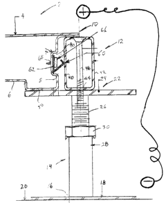
Fig. 1 generally illustrates an access floor panel 2 having a top surface 4
space from a bottom surface 6. The access floor panel 2 can have a variety of
configurations and in one embodiment is rectangular (not shown) having four
sides 8. In another embodiment the panels can be square (not shown).
As best seen in Fig. 5, the top surface 4 extends beyond the bottom
surface so as to define a lip 10 which is adapted to be supported on a
stringer 12.
The stringer 12 is supported at the ends thereof on a pedestal 14 at each end.
The pedestal 14 includes at its lower end thereof 16 a base 18 which is
adapted to contact the ground 20 such as the ground presented by a building
ground.
The pedestal 14 includes at the top end thereof 22 a flat head assembly
24 which is adapted to support the stringer 12. The pedestal 14 has means of
adjusting the height or distance between the head assembly 24 from the base
assembly 18 by means of rotating the threaded shaft 26 about the pedestal
column 28 in a manner well known to those persons skilled in the art. Once the
desired height is reached, the nut 30 tightens the shaft 26 to the pedestal
column
28 in a manner well known to those persons skilled in the art.
The pedestals are arranged in a manner well known to those persons
skilled in the art in a grid pattern. Thereafter, stringers 12 are disposed
substantially horizontally between adjacent pedestals 14 such that the ends 32
of
the pedestal overlap and are supported by the head assembly 24. In particular,
CA 02452038 2011-07-22
6
the head assemblies 24 include a plurality of threaded holes 34 which align
with
holes 44 located in the ends 32 of the stringers 12.
The stringer 12 in one embodiment is generally hollow and tubular in
structure having a stringer top surface 36 spaced from a stringer bottom
surface
38. Furthermore, the stringer has spaced vertically disposed sidewalls 40 and
42
as shown. The top and bottom stringer surfaces 36 and 38 include aligned holes
44 which are adapted to receive screws 46 adapted to be screwed and fastened
to the threaded holes 34 of the pedestal. In this manner, the horizontally
disposed
stringers define a grid structure well known to those persons in the art. The
grid
structure includes grid openings 48 adapted to receive the access floor panel
2
as best illustrated in Fig. 1. The screws 46 have a head which is counter sunk
so
as to lie flush with the stringer top surface 36 as best seen in Fig. 1.
Thereafter
the lip on all four sides of the access floor panel 2 is supported on the top
surface
36 of the stringer 12.
The access floor panel 2 can be constructed in a variety of ways well
known to those persons in the art and in the embodiment shown in Fig. 5
comprises of a formed sheet of metal which includes a bottom surface 6. The
bottom surface 6 is bent or formed so as to produce a bottom support adapted
to
contact the head assembly 24 which in turn is formed or bent to produce the
sides 8 as previously described. The sides 8 continue upwardly and outwardly
so
as to merge with the top surface 4 and define the lip 10 as best seen in Fig.
5.
Other constructions however are possible, including other configurations
whether
square, hexagonal, or rectangle panel.
A deformable means 60 is presented by the access floor panel and
adapted to contact one of the sides 40, 42 of the stringer 12 so as to provide
good electrical contact. In particular the deformable means comprises a clip
62
Soo which is compressible against the support when the floor panel is placed
against
the support.
The clip 62 includes an aperture 64 adapted to receive a fastener such as
a screw 66 through a hole 68 presented by the sidewall 8. The clip 62 is made
CA 02452038 2011-07-22
7
of metal or other electrical conductors such as brass, bronze, copper,
aluminum
or the like. Since the hole 68 presents a bare metal surface to the screw 66
good
electrical conductivity is presented between the top surface 4, sides 8, screw
66
and-spring 60. The stringers 12 thread to the fastener 46, threaded member 26,
support 28 and base assembly 18 are also metal so as to provide good
electrical
conductivity between top surface 4 and bottom 16 of pedestal 4.
The clip 62 includes a back portion 70 and a V-shaped leg 72 disposed
vertically upwardly from the bottom edge of the back portion 70 as best seen
in
Fig. 2. Furthermore the leg 72 includes an inward portion 74 so as to present
a
contact surface 76 to contact one of the sides 40 of the stringer 12.
When the access floor panel 2 is pulled away from the grid the clip 62
presents the contact 76 in its outermost position as shown in Fig. 4. Once the
access floor panel 2 is dropped into the opening 48 of the grid system the
contact
76 is pushed inwardly and assumes the position shown in Fig. 5 as well as the
position shown in dotted lines of Fig. 4. In other words the clip 62 springs
inwardly or is deformed inwardly and presents a contact surface 76 which is
urged against the sides of the stringer 12 to produce good electrical contact.
Furthermore as the access floor panel 2 is removed from the grid structure,
the
clip 62 will spring back to the position shown in Fig. 4 without being caught
by the
stringer 12.
Any shape of clip 62 can be used such as a curved leaf (not shown) or
other shape within in the spirit of this invention so long as the clip 62
springs
against the stringer 12 in a manner described.
In another embodiment the access floor panel 2 has at least one side
which presents a recessed area 80 which is adapted to receive the clip 62. The
'10 recessed area 80 includes the holes 68 for fastening the clip 62 to the
side 8. The
recessed area 80 protects the clip 62 from accidental damage. Furthermore the
clip 62 is disposed in the recessed area 80.
CA 02452038 2011-07-22
8
The grid pattern comprises a plurality of pedestals appropriately spaced to
support the stringers 12.
The structure defined herein has exhibited electrical resistance of the top
surface 4 of the floor panel 2 of in one example of less than 10 ohms to the
bottom of the pedestal 16.
The invention as described includes a device for electrically grounding an
access floor panel 2 to a floor panel support which comprises a clip 62
fastened
to the floor panel where the clip is compressible against the support when the
floor panel is placed against the support.
Moreover the invention describes a floor panel 2 for a raised access floor
defined by a plurality of floor panels 2 supported by a grid of horizontally
disposed stringers 12, each stringer supported at the ends thereof by two
spaced
apart pedestals 14; where the floor panel has a rectangular bottom surface 6
and
a rectangular top surface 4 spaced from the bottom surface 6 by four sides 8
thereof where the top surface 4 extends beyond the bottom surface 6 to define
a
lip 10 where the lip 10 is adapted to be supported by one of the stringers 12.
One of the sides 8 includes a recess 80 adapted to receive a spring clip 62
adapted to spring against the stringer 12 when the floor panel 2 is supported
by
the stringer 12 in the grid. At least one side 8 of the access floor panel 2
includes
the clip 62. However two or three or all sides 8 of the access floor panel 2
can
include the clip 62.
The clip 62 is bent to permit the floor panel 2 to be dropped into the grid so
as to be horizontally supported by the stringers 12 and to compress said clip
against a side 40 of the stringer 12 to make electrical contact with the
stringer 12
into pedestal 14.
The invention described herein shows a clip 62 which is mechanically
fastened to a positive connection of less resistance. The recessed area 80 is
deep enough to allow for a head of a fastener 66 to be spaced from side 40 of
the
CA 02452038 2011-07-22
9
stringer 12 so as to permit the spring action of the clip 62 as described with
the
proper clearance between the panel 2 and the stringer 12.
The brass, bronze, copper or aluminum spring 62 is fastened to the panel
2 and is shaped to allow the panel 2 to be dropped into the access floor grid.
When a panel is dropped into the grid the clip or spring 62 is compressed
making
a positive electrical contact with the stringer. The stringer 12 is
mechanically
connected to the pedestal 14 where grounding occurs.
The upper portion of the clip 62 is shaped and formed so it can be
removed when the panel 2 is lifted out without deformation or damage of its
shape in future use.
The stringer 12 and pedestal 14 can be made of a raw metal or coated
with a conductive finish.
The invention also describes a method of grounding a floor panel in a grid
defined by a plurality of stringers 12 and supported by a plurality of
pedestal 14
comprising the steps of fastening the deformable metal clip 62 to one side 8
of
the floor panel 2, and placing the floor panel 2 into said grid so as to
support said
floor panel 2 on the stringers 14 and compressing said metal clip 62 against
the
stringer 12 so as to make electrical contact thereto.
Although the preferred embodiment as well as the operation and the use
have been specifically described in relation to the drawings, it should be
understood the variations and the preferred embodiment could be achieved by a
person skilled in the art without departing from the spirit of the invention
as
claimed herein.
Various embodiments of the invention have now been described in detail.
Since changes in and/or additions to the above-described best mode may be
made without departing from the nature, spirit or scope of the invention, the
invention is not to be limited to said details.