Note : Les descriptions sont présentées dans la langue officielle dans laquelle elles ont été soumises.
CA 02456578 2004-01-30
, .,
2266.001
GAS BURNER ASSEMBLIES, METHODS FOR
ASSEMBLING, AND GAS FIRED APPLIANCES EMPLOYING SAME
FIELD OF THE INVENTION
[0001] This invention relates generally to gas fired appliances, and more
specifically, to gas burner assemblies for gas fired appliances.
BACKGROUND OF THE INVENTION
[0002] Gas fired appliances such as vented gas fireplace heaters have gained
widespread popularity recently. Typically, a vented gas fireplace heater
includes a
housing having a glass front, a gas burner assembly, and a plurality of
ceramic
logs. The vented gas fireplace heater can be a stand-alone unit with legs,
and/or
be installed in an existing fireplace.
[0003] Conventionally, the gas burner assembly includes a flat stainless steel
top plate connected to a cast iron bottom base with bolts. Assembly requires
drilling vertically-extending holes in the cast iron bottom base which holes
are then
tapped to form screw threads for receiving the bolts. The stainless steel top
plate
requires drilling vertically-extending holes which correspond and align with
the
threaded holes instalied in the cast iron bottom base. Thereafter, the bolts
are
typically manually tightened to attach the stainless steel top plate to the
cast iron
bottom base. Other techniques for assembling a gas burner assembly include
attaching a flat ceramic top plate to the bottom base using an adhesive such
as a
high temperature resistant silicone adhesive.
[0004] There is a need for further gas burner assemblies and methods for
assembly of gas burner assemblies for use in gas fired appliances.
-1-
CA 02456578 2004-01-30
2266.001
SUMMARY OF THE INVENTION
[0005] In a first aspect, the present invention provides a gas burner assembly
which includes a top plate having at least one port for discharging fuel and a
downwardly-depending, peripheral edge having a plurality of spaced-apart
slots, a
bottom base having a peripheral edge disposed within the downwardly-depending,
peripheral edge of the top plate, and wherein the top plate is attached to the
bottom base by displacing a portion of the downwardly-depending, peripheral
edge adjacent to the slots to form a plurality of spaced-apart, inwardly-
extending
tabs disposed under the peripheral edge of the bottom base.
[0006] In a second aspect, the present invention provides a gas burner
assembly which includes a top plate having at least one port for discharging
fuel
and a downwardfy-depending, peripheral edge having a plurality of spaced-apart
slots, a bottom base having a peripheral edge disposed within the downwardly-
depending, peripheral edge of the top plate, a gasket disposed between the
bottom base and the top plate, a venturi tube assembly, and a tube holder for
attaching the venture tube assembly to the bottom base. Additional features of
the gas burner assembly may include the distance between adjacent slots being
greater than a length of the slots. The top plate may be attached to the
bottom
base by expanding a portion of the downwardly-depeneling, peripheral edge
under
the slots to form a plurality of spaced-apart, inwardly-extending tabs
disposed
under the peripheral edge of the bottom base. The gasket and the bottom base
are sandwiched between a bottom surface of the top plate and the tabs and
operable to maintain a gas tight seal between the top plate, the bottom base,
and
the gasket.
[0007] In a third aspect, the present invention provides gas fired appliances
which include a housing, and the above-described gas burner assemblies. At
least one ceramic log may also be disposed in the gas fired appliances.
-2-
CA 02456578 2004-01-30
2266.001
[0008] In a fourth aspect, the present invention provides a method for
assembling a gas burner assembly in which the method includes positioning a
bottom base having a peripheral edge within a top plate having at least one
port
and having a downwardly-depending, peripheral edge with spaced-apart slots
adjacent to the periphery of the top plate. Portions of the downwardly-
depending,
peripheral edge of the top plate adjacent to the slots are displaced to form a
plurality of spaced-apart tabs under the peripheral edge of the bottom base to
attach the top plate to the bottom base.
[0009] in a fifth aspect, the present invention provides an attachment means
which includes a first member having a downwardly-depending, peripheral edge
having a plurality of spaced-apart slots, a second member having a peripheral
edge disposed within the downwardly-depending, peripheral edge of the first
member, and wherein the first member is attached to the second member by
displacing a portion of the downwardly-depending, peripheral edge under the
slots
to form a plurality of spaced-apart, inwardly-extending tabs disposed under
the
peripheral edge of the second member, and the first member and the second
member are formed from different materials having different rates of thermal
expansion. The first member may be attached to the second member by
expanding a portion of the downwardly-depending, peripheral edge under the
slots
to form a piurality of spaced-apart, inwardly-extending tabs disposed under
the
peripheral edge of the second member. A gasket may be disposed between the
first member and the second member adjacent to the peripheral edge.
[0010] In a sixth aspect, the present invention provides a method for
attaching
a first member to a second member. The method includes positioning the second
member having a peripheral edge within the first member having a downwardly-
depending, peripheral edge with spaced-apart slots adjacent to the periphery
of
the first member, and expanding portions of the downwardly-depending,
-3-
CA 02456578 2007-06-21
peripheral edge of the first member adjacent to the slots to form a plurality
of
spaced-apart tabs under the peripheral edge of the bottom base to attach the
first
member to the bottom base.
[0010.1] In a first aspect, the present invention provides a gas burner
assembly comprising: a gas burner having: a top plate comprising stainless
steel
and having at least one port for discharging fuel and a perpendicular,
peripheral
edge having a plurality of horizontally-extending spaced-apart open slots; a
bottom base having a peripheral edge disposed within said peripheral edge of
said top plate; and wherein said bottom base being attached to said top plate
by
plastically-deformed portions under said slots of said peripheral edge of said
top
plate forming a plurality of spaced-apart, inwardfy-extending hollow tabs
disposed
under said peripheral edge of said bottom base.
[0010.2] In a second aspect, the present invention provides a gas burner
assembly comprising: a gas burner having: a top plate comprising stainless
steel
and having at least one port for discharging fuel and a perpendicular
peripheral
edge having a plurality of horizontally-extending spaced-apart open slots; a
bottom base having a peripheral edge disposed within said peripheral edge of
said top plate; a gasket disposed between said bottom base and said top plate;
a
venturi tube assembly; a tube holder for attaching said venture tube assembly
to
said bottom base; and wherein a distance between adjacent slots are greater
than a length of said slots; said bottom base being attached to said top plate
by
plastically-deformed portions under said slots of said peripheral edge of said
top
plate forming a plurality of spaced-apart, inwardly-extending hollow tabs
disposed
under said peripheral edge of said bottom base; and said gasket and said
bottom
base are sandwiched between a bottom surface of said top plate and said tabs
and operable to maintain a gas tight seal between said top plate, said bottom
base, and said gasket.
-4-
CA 02456578 2007-06-21
[0010.3] In a third aspect, the present invention provides a method for
assembling a gas burner assembly, the method comprising: positioning a bottom
base having a peripheral edge within a top plate comprising stainless steel
and
having at least one port and having a perpendicular peripheral edge with
horizontally-extending spaced-apart open slots adjacent to the periphery of
the
top plate; and plastically-deforming portions under the slots of the
peripheral edge
of the top plate to form a plurality of spaced-apart hollow tabs under the
peripheral edge of the bottom base to attach the top plate to the bottom base.
BRIEF DESCRIPTION OF THE DRAWINGS
[0011] The subject matter which is regarded as the invention is particularly
pointed out and distinctly claimed in the concluding portion of the
specification.
The invention, however, may best be understood by reference to the following
detailed description of various embodiments and the accompanying drawings in
which:
[0012] FIG. 1 is a perspective view of a gas fired appliance such as a vented
gas fireplace heater employing a gas burner assembly (not shown in FIG. 1) in
accordance with the present invention;
[0013] FIG. 2 is an exploded perspective view of the gas burner assembly of
FIG. 1 in accordance with the present invention prior to assembly;
[0014] FIG. 3 is a perspective view of the assembled gas burner assembly of
FIG. 2 prior to attachment of the top plate to the bottom base;
[0015] FIG. 4 is a perspective view of the bottom of the assembled gas burner
assembly of FIG. 3 with the top plate attached to the bottom base;
-4a-
CA 02456578 2007-06-21
[0016] FIG. 5 is a bottom view of the assembled gas burner assembly of FIG. 4
with the top plate attached to the bottom base;
[0017] FIG. 6 is an enlarged view of detail 6 of FIG. 5 illustrating the
attachment means for attaching the top plate to the bottom base;
-4b-
CA 02456578 2004-01-30
2266.001
[0018] FIG. 7 is a flowchart of a method of assembling a gas burner assembly
in accordance with the present invention;
[0019] FIGS. 8 and 9 illustrate another embodiment of an attachment means in
accordance with the present invention;
[0020] FIGS. 10 and 11 illustrate another embodiment of an attachment means
in accordance with the present invention; and
[0021] FIGS. 12 and 13 illustrate another embodiment of an attachment means
in accordance with the present invention.
DETAILED DESCRIPTION OF THE INVENTION
[0022] FIG. I illustrates one embodiment of a gas fired appliance such as a
vented gas fireplace heater 10 in accordance with the present invention.
Vented
gas fireplace heater 10 generally includes a housing 12 having a chamber 14
therein and supported by a plurality of feet 15, a pair of doors 16 having
glass
panels, a gas burner assembly (not shown in FIG. 1) disposed in chamber 14,
and
at least one ceramic log 18 disposed in chamber 14 above the gas burner
assembly.
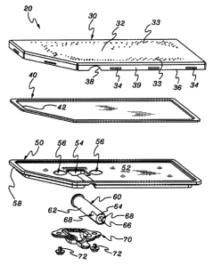
[0023] FIG. 2 illustrates an exploded view of a gas burner assembly 20 in
accordance in the present invention prior to assembly, and which after
assembly,
may be installed in vented gas fireplace heater 10 (FIG. 1). Gas burner
assembly
20 generally includes a top plate 30, a gasket 40, a bottom base 50, a venturi
tube
60, and a tube holder 70.
[0024] As explained in greater detail below, the attachment technique of the
present invention incorporates the use of tabs, eliminates the use of bolts,
-5-
CA 02456578 2004-01-30
2266.001
compensates for the use of materials with different rates of thermal
expansion,
and allows for automated andlor uniform assembly.
[0025] Top plate 30 may include a generally planar member 32 having a
plurality of ports 33 extending therethrough through which fuel such as
natural gas
or propane may be discharged resulting in a desired flame picture or pattern.
Top
plate 30 may be initially formed and cut out from a flat planar member.
Thereafter, the plurality of ports 33 may be drilled or stamped therethrough,
a
plurality of spaced-apart slots 34 adjacent to a peripherally-extending edge
36 cut
or punched therethrough, a rounded notch 38 removed, and the comers between
the adjacent sides of the flat planar member notched or removed. Next, the
peripherally-extending edge may be bent downwardly to form a downwardly-
depending, peripheral edge 39 having the plurality of space-apart slots 34
disposed therein as shown in FIG. 2. The top plate may be formed from
stainless
steel and coated with a high temperature black paint.
[0026] Gasket 40 generally includes a planar member 42 having a central
cutout and a peripheral edge sized and configured for being received along the
bottom surface of top plate 30 adjacent to downwardly-depending, peripheral
edge 39. The gasket may be formed from a fiberglass material such as 1200
Manniglass available from Lydall Industrial Thermal Solutions of Hartford
Connecticut or formed from other suitable materials.
[0027] Bottom base 50 includes a generally flat central portion 52 having an
opening 54 for receiving a flow of fuel, a pair of threaded apertures 56, and
a
peripheral edge or raised lip 58 which is sized and configured for being
received
along the bottom surface of top plate 30 adjacent to downwardly-depending,
peripheral edge 39 with gasket 30 disposed therebetween. The raised lip forms
a
chamber within the gas burner assembly for distributing the gas and air
mixture to
the ports. The bottom base may be may be formed from cast iron.
-6-
CA 02456578 2004-01-30
2266.001
[0028] Venturi tube assembly 60 includes a venturi tube 62 and a cap 64 which
is attached to an end of venturi tube 62 to define a first aperture 66 for
receiving a
flow of fuel and a pair of second apertures 68 for receiving a flow of air for
mixing
with the flow of fuel. Tube holder 70 is attached to bottom base 50 using
screws
72 receivable within threaded apertures 56. The venturi tube and cap may be
formed from aluminum, and the tube holder may be formed from cast iron.
[0029] FIG. 3 illustrates assembled gas burner assembly 20 prior to securing
top plate 30 to the bottom base. For example, venturi tube assembly 60 may be
attached to the bottom base with tube holder 70 using the screws, and
thereafter,
the bottom base may be nested in top plate 30 with the gasket sandwiched
therebetween.
[0030] As shown in FIGS. 4 and 5, thereafter a suitable number of tabs 35 may
be formed in top plate 30 to securely and sealably attach top plate 30 to
bottom
base 50. As best shown in FIG. 6, a portion of the downwardly-depending,
peripheral edge under the slot is displaced or extended to form an inwardly-
extending tab 35 disposed under peripheral edge 58 of bottom base 50 to
sandwich the edge or lip 58 of bottom base 50 and the gasket between the
plurality of tabs and the bottom surface of top plate 50. The slot in the edge
of the
top plate is desirably positioned from the distal most edge of the top plate
so that
the various components may be compressed and/or sandwiched while the tab is
formed resulting in the gasket remaining compressed between the top plate and
the bottom base. For example, desirably, the gasket is resilient and may be
deformed upon assembly to form a gas tight seal between the top plate and the
bottom base.
[0031] For example, the portion of the downwardly-depending, peripheral edge
under the horizontally-extending slot may be deformed or expanded to form
inwardly-extending tab 35. The plurality of inwardly-extending tabs 35 may
-7-
CA 02456578 2004-01-30
2266.001
include a plurality of spaced-apart, generally inwardly extending V-shaped
tabs, or
a plurality of spaced-apart, generally inwardly-extending trapezoidally-shaped
tabs. From the present description, other configurations of the tabs, such as
square, rectangular, curved, cut, other configurations, and combinations
thereof,
may be suitably employed. In addition, the portion of the downwardly-
depending,
peripheral edge under the slot may be twisted, e.g., the lowermost middle
section
may be forced downwardly toward the bottom base.
[0032] In addition, the distance between adjacent slots may be greater than
the
length of the slots, and a suitable number of tabs may be formed to provide a
gas
tight seal with or without a gasket.
[0033] The tabs may be manually formed. Alternatively, the tabs may be
formed using a hydraulically operated device having a tool such as jaws
conforming to the shape of the tab and operable to apply a constant force for
uniformly forming the tabs.
[0034] As illustrated in FIG. 7, a method 80 for assembling a gas burner
assembly may be represent by the steps of forming a top piate having a
plurality
of spaced-apart slots adjacent to the periphery of the top plate, at 82, and
forming
a downwardly-depending, peripheral edge with the spaced-apart slots, at 84. At
86, a bottom base having a peripheral edge is provided, and at 88, the bottom
base is positioned within the downwardly-depending, peripheral edge with the
slots. Thereafter, at 90, portions of the downwardly-depending, peripheral
edge of
the top plate are displaced or extended to form a plurality of spaced-apart
tabs
under the peripheral edge of the bottom base to attach the top plate to the
bottom
base. Desirably, the components are pressed together prior to and during the
forming of the tabs.
-8-
CA 02456578 2004-01-30
2266.001
[0035] Further, the attachment technique of the present invention may be used
on applications which require the attachment of a first member to a second
member. For example, the first member may have a downwardly depending,
peripheral edge having horizontally- and/or vertically-extending slots which
allow a
portion of the downwardly depending, peripheral edge to be displaced and/or
expanded under a peripheral edge of the second member. This technique is
desirably suitable where the first member and the second member have different
thermal properties such as thermal expansion rates. 'The distance between
adjacent slots may be greater than the length of the slots, and a suitable
number
of tabs may be formed to provide a gas tight seal with or without a gasket.
[0036] FIGS. 8-13 illustrate alternative embodiments of the present invention
for use in a burner assembly and/or connecting a first member to a second
member. For example, FIG. 8 illustrates a downwardly-depending peripheral
edge 136 having a horizontally-extending slot 134 and a vertically-extending
slot
135 connected to one end of horizontally-extending slot 136. As shown in FIG.
9,
a portion 135 of the downward ly-depend ing peripheral edge can be displaced
or
bent inwardly under a second member 158.
[0037] FIGS. 10 and 11 illustrates a downwardly-depending peripheral edge
236 having a horizontally-extending slot 134 and a vertically-extending slot
137
connected to the middle of horizontally-extending slot 134. As shown in FIG.
11,
portions 235 of the downwardly-depending peripheral edge can be displaced or
bent inwardly under a second member 258.
[0038] FIGS. 12 and 13 illustrates a downwardly-depending peripheral edge
336 having a pair of vertically-extending slots 37. As shown in FIG. 13, a
portion
335 of the downwardly-depending peripheral edge can be displaced or bent
inwardly under a second member 358.
-9-
CA 02456578 2004-01-30
2266.001
[0039] From the present description, it will be appreciated by those skilled
in
the art that first member may have a plurality of spaced-apart individual
vertically-
extending slots employed to form the tabs. One or more of the vertical edges
may
be displaced or extended over or under the second member, e.g., by being bent
on a 45-degree angle.
[0040] Furthermore, the location, size and/or configuration of the slots may
vary so that when the various components are assembled, an interference type
fit
connection will occur along the engaging surface portion of the slot and the
bottom base.
[0041] The attachment technique of the present invention utilizing tabs also
allows for independent rates of expansion to occur between the top plate and
the
bottom base, thereby effectively eliminating thermal stresses that could
result in
deformation of the various materials and reduced service life of the gas
burner
assembly compared to conventional techniques for attaching the top plate to
the
bottom base of the gas burner assembly. With dissimilar materials such as
dissimilar materials having different rates of thermal expansion, the
attachment
technique results in generally self adjusting pressure between the top plate,
the
gasket, and the bottom base. In addition, the present invention provides a
generally fastener-less and tool-less assembly process which eliminates the
need
for drilling and tapping holes in the base, and drilling holes in the top
plate while
providing a structurally reliable assembled gas burner assembly. Thus, the gas
burner assembly may be readily assembled without the use of conventional
fasteners such as bolts. The technique for assembling the gas burner assembly
may also be automated for a uniform assembly compared to manual hand
assembly of attaching bolts.
[0042] While the gas burner assembly of the present invention has been
described in connection with use in gas fired appliances such as vented gas
-10-
.._ .
w ..H,., ,.. .......
. . . _ _ . _ .. . _ ... , . . n.. _.. ..~ u _. . _ _
CA 02456578 2004-01-30
2266.001
fireplace heaters, it will be appreciated that the gas burner assemblies may
also
be used in barbeques, outdoor and indoor gas cooking grills, gas fumaces, gas
boilers, gas fireplaces, gas fired space heating appliances, and other
applications
requiring a gas burner assembly.
[0043] Thus, while various embodiments of the present invention have been
shown and described, it will be appreciated by those skilled in the art that
many
changes and modifications may be made thereunto without departing from the
spirit and scope of the invention.
-11-
.._._.._._.~.._._._..~._._...~.___ .._._._
r~.~