Sélection de la langue

Search

Sommaire du brevet 2457177 

Énoncé de désistement de responsabilité concernant l'information provenant de tiers

Une partie des informations de ce site Web a été fournie par des sources externes. Le gouvernement du Canada n'assume aucune responsabilité concernant la précision, l'actualité ou la fiabilité des informations fournies par les sources externes. Les utilisateurs qui désirent employer cette information devraient consulter directement la source des informations. Le contenu fourni par les sources externes n'est pas assujetti aux exigences sur les langues officielles, la protection des renseignements personnels et l'accessibilité.

Disponibilité de l'Abrégé et des Revendications

L'apparition de différences dans le texte et l'image des Revendications et de l'Abrégé dépend du moment auquel le document est publié. Les textes des Revendications et de l'Abrégé sont affichés :

  • lorsque la demande peut être examinée par le public;
  • lorsque le brevet est émis (délivrance).
(12) Brevet: (11) CA 2457177
(54) Titre français: CAGE DE LAMINOIR DESTINEE AU LAMINAGE DE DIFFERENTS LAMINES NECESSITANT DIFFERENTES FORCES DE LAMINAGE
(54) Titre anglais: ROLLING MILL STAND FOR THE ROLLING OF DIFFERENT ROLLED STOCK WHICH REQUIRE DIFFERENT ROLLING FORCES
Statut: Réputé périmé
Données bibliographiques
(51) Classification internationale des brevets (CIB):
  • B21B 31/32 (2006.01)
(72) Inventeurs :
  • DENKER, WOLFGANG (Allemagne)
(73) Titulaires :
  • SMS SIEMAG AKTIENGESELLSCHAFT (Allemagne)
(71) Demandeurs :
  • SMS DEMAG AKTIENGESELLSCHAFT (Allemagne)
(74) Agent: FETHERSTONHAUGH & CO.
(74) Co-agent:
(45) Délivré: 2010-09-07
(86) Date de dépôt PCT: 2002-08-16
(87) Mise à la disponibilité du public: 2003-03-13
Requête d'examen: 2007-05-14
Licence disponible: S.O.
(25) Langue des documents déposés: Anglais

Traité de coopération en matière de brevets (PCT): Oui
(86) Numéro de la demande PCT: PCT/EP2002/009195
(87) Numéro de publication internationale PCT: WO2003/020452
(85) Entrée nationale: 2004-02-12

(30) Données de priorité de la demande:
Numéro de la demande Pays / territoire Date
101 41 180.4 Allemagne 2001-08-22

Abrégés

Abrégé français

L'invention concerne une cage de laminoir destinée au laminage de différents laminés nécessitant différentes forces de laminage. Cette cage comprend des cylindres de travail, des cylindres d'appui, éventuellement un dispositif de pliage destiné aux cylindres de travail et éventuellement un équipement destiné au réglage et à l'équilibrage de cylindres d'appui et des paires de cylindres de réglage (3) placés entre les montants de laminoir (1) et les empoises (2) permettent d'éviter les grandes pertes par frottement, de telle façon que les cylindres de réglage (3) soient respectivement composés d'un cylindre télescopique (4) qui renferme un premier cylindre concentrique (5) de grand diamètre pour des forces laminage élevées et un deuxième cylindre concentrique (15) de petit diamètre pour de petites forces de laminage.


Abrégé anglais


The invention relates to a roll stand for rolling different rolling stock that
requires different roll separating forces. The inventive roll stand comprises
working rolls, back-up rolls, optionally a roll bending device for the working
rolls and optionally a device for adjusting and balancing the back-up rolls,
and pairs of adjustment cylinders (3) between the roll stands (1) and the
chocks (2). According to the invention, the adjustment cylinders (3) consist
of respective telescope cylinders (4), in which a first, concentric cylinder
(5) having a large diameter is provided for high roll separating forces and a
second, concentric cylinder (15) having a smaller diameter is provided for
lower roll separating forces, thereby avoiding high friction losses.

Revendications

Note : Les revendications sont présentées dans la langue officielle dans laquelle elles ont été soumises.


CLAIMS

1. A rolling mill stand for the rolling of different
rolled stocks which require different rolling forces, has a lower
working roll and an upper working roll, back-up rolls juxtaposed
with the working rolls, optionally a roll bending device for the
working rolls and optionally devices for adjusting and balancing
the back-up rolls and with pairs of adjusting cylinders (3) between
the rolling mill stand (1) and the chocks (2), characterized in
that the adjusting cylinders (3) are each comprised of a
telescoping cylinder (4) in which a first concentric cylinder (5)
with a larger diameter for higher rolling forces and a second
concentric cylinder (15) for a smaller diameter for smaller rolling
forces, are provided, whereby the pressure medium connection
[fitting] (11) for the annular pressure compartment (5a) of the
large piston (5d) forms a connection (20) to the underside (15b) of
the smaller piston (15a).
2. The rolling mill stand according to claim 1
characterized in that the first larger cylinder (5) with the larger
diameter forms an annular pressurizable compartment (5a) whose
pressure medium presses a larger piston ring (5b) against the
cylinder bottom (5c).
3. A rolling mill stand according to one of claims 1 or
2 characterized in that the smaller piston (15a) of the second
cylinder (15) with a smaller diameter forms in the interior (21) of


-9-


the larger piston (5) a pressure chamber (13) for actuating the
smaller piston (15a).
4. A rolling mill stand according to claim 3
characterized in that the pressure medium fitting (14) for the
smaller piston (15a) extends through the cylinder wall (5e) and
through the cylinder bottom (5c) of the larger cylinder (5).
5. A rolling mill frame according to one of claims 1
through 4 characterized in that the first larger cylinder (5) has a
pressure medium fitting (12) opening in the region of the cylinder
bottom (5c).
6. The rolling mill stand according to one of claims 1
through 5 characterized in that the first, larger cylinder (5) is
closable by means of a closure ring (8) sealing relative to the
larger piston (5d) and to which the pressure medium fitting (11)
for the outer annular compartment (5a) is connected.


-10-

Description

Note : Les descriptions sont présentées dans la langue officielle dans laquelle elles ont été soumises.


CA 02457177 2004-02-12
22777 PCT/EP02/09195 Transl. of WO 03/020452 A1
AMENDED VERSION
[TRANSLATION]
ROLLING MILL STAND FOR THE ROLLING OF DIFFERENT ROLLED
STOCK WHICH REQUIRE DIFFERENT ROLLING FORCES
The invention relates to a rolling mill stand for the
rolling of different rolled stock which require different rolling
forces and having a lower working roll and an upper working roll,
back up rolls juxtaposed with the working rolls, optionally a roll
bending device for the working rolls, and optionally devices for
the setting and balancing of the back up rolls and pairs of
adjusting cylinders between the roll stands and the chocks.
The hydraulic adjusting cylinders are used to generate
the rolling force in the rolling mill. For the rolling mill a high
product selectivity requires that the rolling mill be capable of
having large rolling force differences between the individual
products which are to be produced by a given rolling mill stand.
It is known to apply the different rolling forces with
two adjusting cylinders for each rolling mill stand. In this case,
however, the production of a lower rolling force may involve the
same friction losses as a higher rolling force which can give rise
to difficulties in control. A greater part of the higher friction
losses may contribute to loading of the seals, the piston rod and
the piston in a piston-and-cylinder unit.
- 1 -


CA 02457177 2004-02-12
22777 PCT/EP02/09195 Transl. of WO 03/020452 A1
AMENDED VERSION
To adjust the rolling force in a rolling mill stand,
especially in a strip rolling mill stand for hot or cold rolling,
it is known (DE 40 10 662 C2), in maintaining in a simple way the
percentage of rolling force fluctuations in the course of rolling
force control over an entire rolling force range, so as to be
exceptionally small, to provide both adjusting cylinders with a
respective cylinder housing and a cylinder pin, with a hat-shaped
piston which is guided in a cylinder collar and in which the
central piston surface formed by the internal hat button and the
annular piston surface formed by the peripheral rim of the hat
shaped piston are subjected to the pressure medium independently
from one another or individually, or in common. This system,
however, provides a plurality of friction surfaces which can
complicate the control of the system.
From the Japanese Patent Document-60-162513 a rolling
mill stand is known which indeed operates without chocks but
wherein the adjustment of the rolling force utilizes a telescoping
cylinder. With this system high roll reductions can be obtained
with higher surface quality.
In Japanese Patent Document 62 130 705, also no
arrangement of a telescoping cylinder between chock and rolling
mill stand is contemplated. The telescoping cylinder is arranged
in the bottom of the roll stand and is provided for the back up
rolls.
- 2 -


CA 02457177 2004-02-12
22777 PCT/EP02/09195 Transl. of WO 03/020452 A1
AMENDED VERSION
The rolling mill stand described at the outset is known
from EP-A-0 618 019. There single piston-cylinder units are
already provided between the roll stand and the chocks for the
working rolls.
The invention has as its object to reduce such friction
losses and thereby enable a more precise control.
The object which has been set forth is achieved according
to the invention in that setting cylinders each are comprised of a
telescoping cylinder in which a first concentric cylinder is
provided with a larger diameter for producing higher rolling forces
and a second concentric cylinder is provided with a smaller
diameter for producing smaller rolling forces, whereby the
hydraulic medium fitting or connection for the annular pressure
compartment of the large piston forms a connection to the underside
of the small piston. In this case friction forces arise only at
the seals between the cylinder and the respective pistons. The
friction losses are as a result smaller as a whole and thus allow a
more precise control of the rolling force. In addition, by this
connection to the underside, structural space can be saved.
As a development of this basic concept it is proposed
that the first larger cylinder with the greater diameter, form an
outer annular pressurizable compartment whose pressure medium
presses a larger piston ring against the cylinder bottom. The
advantage is that the larger piston, during the actuation of the
- 3 -


CA 02457177 2004-02-12
22777 PCT/EP02/09195 Transl. of WO 03/020452 A1
AMENDED VERSION
smaller piston, finds itself in a rest position and with smaller
rolling forces, the friction at the larger piston can be completely
eliminated so that friction only arises at the smaller piston
which is substantially reduced.
In a refinement of the invention it is provided that the
smaller piston of the second cylinder with the smaller diameter
form within the larger piston a pressurizable compartment for the
actuation of the smaller piston. This allows use of an advantage
of the telescoping system, which is connected with a significant
space saving.
A further feature of the invention provides that the
pressure medium connection for the smaller cylinder extends through
the cylinder wall and through the cylinder bottom of the larger
cylinder. The advantage resides in a shorter medium line and in a
separation of the pressure medium connections to two sides of the
setting cylinder.
In a further refinement it is proposed that the pressure
medium connection for the annular pressurizable compartment of the
larger piston form a connection to the underside of the smaller
piston. This also leads to a saving in the space required for the
structure.
A further advantageous refinement has the first or larger
cylinder so that it can be closed by means of a closure ring
sealing the larger piston and defining an outer annular
- 4 -


CA 02457177 2004-02-12
22777 PCT/EP02/09195 Transl. of WO 03/020452 A1
AMENDED VERSION
pressurizable compartment to which a fluid medium fitting for that
outer compartment is connected. The closure ring can receive the
sealing ring which seals against the larger piston and in part
defines the annular pressurizable compartment.
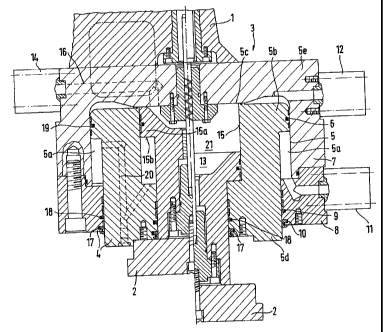
In the sole Figure of the drawing a rolling mill stand
has been shown for the rolling of different rolled stock which may
require different rolling forces and which can receive upper and
lower working rolls, not illustrated in detail, the back-up rolls
juxtaposed with the working rolls, optionally a roll bending device
for the working rolls and optionally devices for adjusting and
balancing the back-up rolls. Pairs of adjusting cylinders 3 have
been illustrated between the roll stand 1 and the chocks 2.
The adjusting cylinders 3 are each comprised of a
telescoping cylinder 4 in each of the telescoping cylinders 4 there
is a respective first larger cylinder 5 with an outwardly lying
annular pressurizable compartment 5a which is defined by a larger
piston ring 5b. The larger piston 5d is sealed by means of a
larger annular seal 6 in the cylinder housing 7.
Therebelow the cylinder housing 7 is closed by means of a
closure ring 8 which also has annular seals 9 and 10 which seal
against the larger diameter piston 5d. Upon pressurization through
the hydraulic fitting 11 opening into the annular pressurizable
compartment 5a, the larger diameter piston 5d is displaced against
the cylinder bottom 5c as has been illustrated. The fluid
- 5 -


CA 02457177 2004-02-12
22777 PCT/EP02/09195 Transl, of WO 03/020452 Al
AMENDED VERSION
pressure on the opposite side which would amount to a
counterpressure, is drained via the pressure fitting 12. Within
the first larger diameter piston 5d, a pressurizable compartment 13
is formed which can be pressurized by the fitting 14. The pressure
compartment 13 receives a second smaller diameter cylinder 15 which
slides in the larger diameter piston 5d and which encloses a second
smaller diameter piston 15a. The fluid pressure fitting 14
communicates with the pressurizable compartment 13 via a fluid
medium passage 16 which runs through the upper region of the
cylinder housing 7. The second smaller piston 15a is sealed by
corresponding sealed rings 17 and 18 whose diameter is smaller than
the second smaller cylinder 15. A further sealing ring 19 is
located on the smaller piston 15a within the larger piston 5d.
The pressure medium fitting 14 feeds the hydraulic fluid through
the cylinder wall 5e and through the cylinder bottom 5c.
In the left half of the illustration, the smaller piston
15a is shown in its upper position and in the right half of the
illustration in its lower position.
The fluid medium fitting 11 provides a communication 20
for the larger annular pressurizable compartment 5a to the
underside 15b of the smaller piston 15a.
The smaller piston 15a of the second smaller cylinder 15
forms in its interior 21 the pressurizable compartment 13 for
actuation of this smaller piston 15.
- 6 -


CA 02457177 2004-02-12
22777 PCT/EP02/09195 Transl. of WO 03/020452 A1
AMENDED VERSION
_ 7 _


CA 02457177 2004-02-12
22777 PCT/EP02/09195 Transl. of WO 03/020452 A1
AMENDED VERSION
Reference Character List


1 Roll mill stand


2 Chocks


3 Adjusting cylinder


4 Telescoping cylinder


First Larger cylinder


5a Annular pressurizable compartment


5b Larger piston ring


5c Cylinder bottom


5d Larger piston


5e Cylinder wall


6 Annular seal


7 Cylinder housing


8 Closure ring


9 Annular seal


Annular seal


11 Pressure medium fitting


12 Pressure medium fitting


13 Pressurizable compartment


14 Pressure medium fitting


15a Second smaller diameter cylinder


15b Piston


16 Pressure medium passage


17 Sealing ring


18 Sealing ring


19 Sealing ring


Communication


21 Interior of the Larger piston


_ g _

Dessin représentatif
Une figure unique qui représente un dessin illustrant l'invention.
États administratifs

Pour une meilleure compréhension de l'état de la demande ou brevet qui figure sur cette page, la rubrique Mise en garde , et les descriptions de Brevet , États administratifs , Taxes périodiques et Historique des paiements devraient être consultées.

États administratifs

Titre Date
Date de délivrance prévu 2010-09-07
(86) Date de dépôt PCT 2002-08-16
(87) Date de publication PCT 2003-03-13
(85) Entrée nationale 2004-02-12
Requête d'examen 2007-05-14
(45) Délivré 2010-09-07
Réputé périmé 2013-08-16

Historique d'abandonnement

Il n'y a pas d'historique d'abandonnement

Historique des paiements

Type de taxes Anniversaire Échéance Montant payé Date payée
Le dépôt d'une demande de brevet 400,00 $ 2004-02-12
Enregistrement de documents 100,00 $ 2004-05-13
Taxe de maintien en état - Demande - nouvelle loi 2 2004-08-16 100,00 $ 2004-07-20
Taxe de maintien en état - Demande - nouvelle loi 3 2005-08-16 100,00 $ 2005-07-22
Taxe de maintien en état - Demande - nouvelle loi 4 2006-08-16 100,00 $ 2006-07-20
Requête d'examen 800,00 $ 2007-05-14
Taxe de maintien en état - Demande - nouvelle loi 5 2007-08-16 200,00 $ 2007-08-10
Taxe de maintien en état - Demande - nouvelle loi 6 2008-08-18 200,00 $ 2008-08-06
Taxe de maintien en état - Demande - nouvelle loi 7 2009-08-17 200,00 $ 2009-07-23
Enregistrement de documents 100,00 $ 2009-08-11
Taxe finale 300,00 $ 2010-06-10
Taxe de maintien en état - Demande - nouvelle loi 8 2010-08-16 200,00 $ 2010-06-10
Taxe de maintien en état - brevet - nouvelle loi 9 2011-08-16 200,00 $ 2011-08-04
Titulaires au dossier

Les titulaires actuels et antérieures au dossier sont affichés en ordre alphabétique.

Titulaires actuels au dossier
SMS SIEMAG AKTIENGESELLSCHAFT
Titulaires antérieures au dossier
DENKER, WOLFGANG
SMS DEMAG AKTIENGESELLSCHAFT
Les propriétaires antérieurs qui ne figurent pas dans la liste des « Propriétaires au dossier » apparaîtront dans d'autres documents au dossier.
Documents

Pour visionner les fichiers sélectionnés, entrer le code reCAPTCHA :


Pour visualiser une image, cliquer sur un lien dans la colonne description du document. Pour télécharger l'image (les images), cliquer l'une ou plusieurs cases à cocher dans la première colonne et ensuite cliquer sur le bouton "Télécharger sélection en format PDF (archive Zip)" ou le bouton "Télécharger sélection (en un fichier PDF fusionné)".

Liste des documents de brevet publiés et non publiés sur la BDBC .

Si vous avez des difficultés à accéder au contenu, veuillez communiquer avec le Centre de services à la clientèle au 1-866-997-1936, ou envoyer un courriel au Centre de service à la clientèle de l'OPIC.


Description du
Document 
Date
(yyyy-mm-dd) 
Nombre de pages   Taille de l'image (Ko) 
Revendications 2004-02-12 2 61
Abrégé 2004-02-12 1 20
Dessins 2004-02-12 1 58
Description 2004-02-12 8 251
Dessins représentatifs 2004-02-12 1 52
Page couverture 2004-04-05 2 72
Description 2009-09-17 9 291
Revendications 2009-09-17 2 75
Abrégé 2009-12-10 1 20
Dessins représentatifs 2010-08-16 1 34
Page couverture 2010-08-16 2 70
Cession 2004-02-12 2 87
PCT 2004-02-12 10 411
Correspondance 2004-04-01 1 27
PCT 2004-02-12 4 174
Cession 2004-05-13 2 66
Cession 2009-08-11 18 785
Poursuite-Amendment 2007-05-14 1 45
Poursuite-Amendment 2009-03-18 2 46
Poursuite-Amendment 2009-09-17 6 211
Correspondance 2010-06-10 1 39
Taxes 2010-06-10 1 34