Sélection de la langue

Search

Sommaire du brevet 2474818 

Énoncé de désistement de responsabilité concernant l'information provenant de tiers

Une partie des informations de ce site Web a été fournie par des sources externes. Le gouvernement du Canada n'assume aucune responsabilité concernant la précision, l'actualité ou la fiabilité des informations fournies par les sources externes. Les utilisateurs qui désirent employer cette information devraient consulter directement la source des informations. Le contenu fourni par les sources externes n'est pas assujetti aux exigences sur les langues officielles, la protection des renseignements personnels et l'accessibilité.

Disponibilité de l'Abrégé et des Revendications

L'apparition de différences dans le texte et l'image des Revendications et de l'Abrégé dépend du moment auquel le document est publié. Les textes des Revendications et de l'Abrégé sont affichés :

  • lorsque la demande peut être examinée par le public;
  • lorsque le brevet est émis (délivrance).
(12) Demande de brevet: (11) CA 2474818
(54) Titre français: DISPOSITIF DE FIXATION
(54) Titre anglais: CLAMPING DEVICE
Statut: Morte
Données bibliographiques
(51) Classification internationale des brevets (CIB):
  • B25B 5/14 (2006.01)
  • B25B 5/00 (2006.01)
  • B25B 5/04 (2006.01)
  • B25B 5/08 (2006.01)
  • B25B 5/10 (2006.01)
  • F16L 3/08 (2006.01)
(72) Inventeurs :
  • PACAK, JOHN (Canada)
(73) Titulaires :
  • PACAK, JOHN (Canada)
(71) Demandeurs :
  • PACAK, JOHN (Canada)
(74) Agent: BATTISON WILLIAMS DUPUIS
(74) Co-agent:
(45) Délivré:
(22) Date de dépôt: 2004-07-16
(41) Mise à la disponibilité du public: 2006-01-16
Licence disponible: S.O.
(25) Langue des documents déposés: Anglais

Traité de coopération en matière de brevets (PCT): Non

(30) Données de priorité de la demande: S.O.

Abrégés

Désolé, les abrégés concernant le document de brevet no 2474818 sont introuvables.

Revendications

Note : Les revendications sont présentées dans la langue officielle dans laquelle elles ont été soumises.


8
CLAIMS:

1. An apparatus for clamping to an outside surface of an object
comprising:
a retainer for attaching to the outside surface the object, the retainer
including first and second sections with elements thereon attaching together
so that
the sections together form a collar having an inner surface surrounding the
outer
surface;
and at least one protruding member extending from the inner surface
generally inwardly for engaging into the outer surface of one of the said
sections for
engaging the said object.
2. Apparatus according to Claim 1 wherein the object is a rod.
3. Apparatus according to Claim 1 wherein the first and second
section snap fasten together.
4. Apparatus according to Claim 1 wherein one of the sections has
a pin as a protruding member radial to the rod.
5. Apparatus according to Claim 1 wherein one of the sections
has blade as the protruding member the blade defining an edge lying as a chord
to
the surface of the rod in a radial plane of the rod.
6. Apparatus according to Claim 1 wherein one element has a pin
and the other at least one blade.
7. Apparatus according to Claim 1 wherein one element is
mounted on the other for pivotal movement.


9
8. Apparatus according to Claim 1 wherein the elements move
into engagement along a line radial to the rod and include guide members
thereon
for guiding the movement.

Description

Note : Les descriptions sont présentées dans la langue officielle dans laquelle elles ont été soumises.

CA 02474818 2004-07-16
CLAMPING DEVICE
This invention relates generally to clamping devices, and, more
particularly to a clamping device that clamps to rod or tube materials using a
tooth
and pin system that prevents the clamp from rotating and translating along the
shaft.
SUMMARY OF THE INVENTION
It is one object of the invention to provide a method of clamping
According to one aspect of the invention there is provided an
apparatus for clamping to an outside surface of an object comprising:
a retainer for attaching to the outside surface the object, the retainer
including first and second sections with elements thereon attaching together
so that
the sections together form a collar having an inner surface surrounding the
outer
surface;
and at least one protruding member extending from the inner surface
generally inwardly for engaging into the outer surface of one of the said
sections for
engaging the said object.
Preferably the object is a rod.
Preferably the object is a rod formed of UHMW polyethylene or similar
plastics material.
Preferably the first and second section snap fasten together.
Preferably one of the sections has a pin as a protruding member radial
to the rod.
Preferably one of the sections has blade as the protruding member
the blade defining an edge lying as a chord to the surface of the rod in a
radial plane

CA 02474818 2004-07-16
2
of the rod.
Preferably one element has a pin and the other at least one blade.
Preferably one element is mounted on the other for pivotal movement.
Preferably the elements move into engagement along a line radial to
the rod and include guide members thereon for guiding the movement.
This invention relates generally to clamping devices, and, more
particularly to a clamping device that clamps to rod or tube materials
utilizing a tooth
and pin system to prevents the clamp from rotating and translating along the
shaft
after it has been engaged.
BRIEF DESCRIPTION OF THE DRAWINGS
One embodiment of the invention will now be described in conjunction
with the accompanying drawings in which:
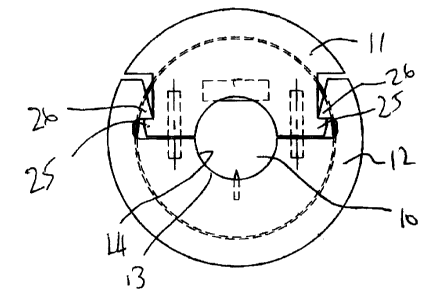
Figure 1 is a side elevational view of the first embodiment of a clamp
according to the present invention.
Figure 2 is a side elevational view of the embodiment of Figure 1 in a
partly opened conditioned.
Figure 3 is a side elevational view of a second embodiment according
to the present invention in the close clamping position.
Figure 4 is a side elevation view similar to that of Figure 3 in the open
position.
Figures 5, 6, 7 and 8 are various views of one part of the clamp of
Figure 1.

CA 02474818 2004-07-16
3
Figures 9, 10, 11 and 12 are various views of the second part of
the clamp of Figure 1.
DETAILED DESCRIPTION
In Figures 1 and 2 is shown a first embodiment of a clamp for clamping
around a rod 10 which includes a first section 11 and a second section 12
which
clamp together to engage around the outer surface 13 of the rod 10. The rod 10
is
circular in cross-section but this is not necessary and other shapes can be
clamped
provided an inside surface 14 of the clamp is arranged to match the outside
surface
13. However primary the arrangement is designed for cylindrical rods where it
is
difficult to clamp an element to the outside surface.
This is particularly applicable in regard to ultra high molecular weight
(UHMW) polyethylene which exhibits very low friction so that frictional
engagement
provides little resistance to movement and also can be shaved by elements
engaging the surface to remove an outside piece of the surface. Thus the
present
invention is concerned with materials of this type or other plastics materials
which
are difficult to clamp in view of there surface characteristics but yet can be
penetrated by a shape object punched or pressed into the outside surface.
The clamp for engaging around the rod 10 is provided by the first
element 11 and the second element 12. The first element is shown in more
detail in
Figures 5 through 8.
The outside surface of the element is designed for a particular use but
can be shaped in any required manner to provide whatever function is required.
The

CA 02474818 2004-07-16
4
embodiment shown the outside surface defines a channel for receiving a thread
but his is merely one example of various different functions.
Thus the element 11 includes an inside surface portion 16 which is
semi-cylindrical for clamping around one half of the rod 10. At a position
along the
length of the semi-cylindrical surface 16 is provided a blade 17 which is
molded into
the body of the element so that an edge 18 of the blade 18 defines a chord of
the
circle forming the surface 16. In the example shown there are two such blades
17
and 19. The use of two blades reduces the tendencies of the clamp to twist on
the
rod about an axis at right angles to the rod since the rod is engaged by the
two axial
spaced blades 17 and 19. However a single blade can be used which would
generally be located half way along the surface 16. The blade thus lies in a
radial
plane of the axis of the rod so that it engages into the rod in a clamping
action within
a radial plane of the rod into a depth of the rod so the edge 18 forms a chord
of the
outside surface of the rod. The depth of the blade is selected to provide a
significant
and sufficient engagement while allowing the blade to be penetrated into its
location
simply by pressure from a compressing or an impact tool.
The second element is shown in Figures 9 through 12 and provides a
surface portion 20 which is also semi-cylindrical and matches the semi-
cylindrical
surface 16. This part 11 has with it its surface 20 at a position generally
midway
along a spike or pin 21 having a pointed end 22 which can be punctured into
the
surface of the rod.. A single pin can be used or alternatively two pins can be
used at
axial spaced positions. The pin is radial and the pin extends along a
direction of

CA 02474818 2004-07-16
movement of the elements 11 and 12 as they are clamed together. Thus the pin
is
forced into the rod in a radial direction toward the axis of the rod so that
the rod in
not bend and has no tendency to twist to either side as it moves directly
radically into
the rod in the puncturing action.
5 The embodiment may use merely a single pin on one of the elements
11 and 12 or may include a pin on each of the elements. Thus the blades can be
omitted and replaced by one or more pins.
However the cooperation of the single and the blades provides a
particularly effective action, bearing in mind that the outside diameter or
the rod can
vary significantly due to tolerances in manufacture so that the inside surface
of the
clamp may not accurately match the outside surface of the rod. Thus the
engagement of the pin in one side and the engagement of the blades on the
other
side prevent axial movement of the clamp along the rod, prevent rotation of
the
clamp around the rod and prevent twisting of the clamping member about axis at
right angles to the rod.
In Figures 1 and 2 the clamping elements 11 and 12 are arranged to
snap together by cooperating abutments 25 on the element 11 and 26 on the
element 12. These abutments provide shoulders for engagement in the clamped
position surrounding the rod and provide inclined surfaces 28 which can slide
over
one another in the application of the clamp onto the rod as the element 11 is
moved
toward the element 12 along a line L which directly along the length of the
pin 21.
The shoulders 28 must slide over one another slightly distorting the injection
molded

CA 02474818 2004-07-16
6
body of each of the elements or one of the elements so that the shoulder can
snap into engagement to hold the clamping elements fixed together. In the
embodiment shown there have provided guide pins 30 which guide the movement of
the element s along the line L. These pins also prevent axial movement of one
element relative to the other where engagement has been completed. However the
pins 30 provide only one example of the arrangements which can be used to
provide
this linear directional movement and to hold the elements against relative
axial
movement. Other elements can be molded into the structure to provide such
guiding
effects.
In the embodiment of Figures 3 and 4, the same blades 17 and 21 are
used in a similar arrangement which clamps around a rod 10. However in this
arrangement the element 11A is pivoted on the element 12A by way of a pivot
connection 40 providing a pivot axis 41 lying parallel to the axis of the rod.
Thus as
shown in Figure 4, the clamp can be opened to allow the rod 10 to be inserted
and
then the element s11A and 12 A are moved towards one another by rotation
around
the axis of the pivot pin 40. A single abutment 25 on the portion 11A thus
cooperates with a single short abutment 26A on the element 12A. Again these
elements slide over one another by inclined surfaces until the shoulders
engage in a
snap action holding the clamping element closed. In this arrangement there is
no
requirement for guiding action since the pin 40 holds the elements in the
required
axial position and guides the relative movement in the clamping action. The
pin 21
mounted on the element 12A is arrangement to engage into the rod first so that
it

CA 02474818 2004-07-16
7
can be moved directly radial to the rod before the element 11A is brought onto
the rod and clamped against the element 12A thus bringing the blades 17 into
engagement with the opposite side of the rod. The blades 17 can move in a
direction which is not linear since they can accommodate the necessary arcuate
movement around the pivot pin 40 whereas a pin would have difficulty in
accommodating such movement due to the fact that the pin requires to move in
the
radial direction without and side to side movement in order to provide the
best
penetrating action.
Since various modifications can be made in my invention as herein
above described, and many apparently widely different embodiments of same made
within the spirit and scope of the Claims without department from such spirit
and
scope, it is intended that all matter contained in the accompanying
specification shall
be interpreted as illustrative only and not in a limiting sense.

Dessin représentatif
Une figure unique qui représente un dessin illustrant l'invention.
États administratifs

Pour une meilleure compréhension de l'état de la demande ou brevet qui figure sur cette page, la rubrique Mise en garde , et les descriptions de Brevet , États administratifs , Taxes périodiques et Historique des paiements devraient être consultées.

États administratifs

Titre Date
Date de délivrance prévu Non disponible
(22) Dépôt 2004-07-16
(41) Mise à la disponibilité du public 2006-01-16
Demande morte 2007-04-17

Historique d'abandonnement

Date d'abandonnement Raison Reinstatement Date
2006-04-18 Inachevé
2006-07-17 Taxe périodique sur la demande impayée

Historique des paiements

Type de taxes Anniversaire Échéance Montant payé Date payée
Le dépôt d'une demande de brevet 200,00 $ 2004-07-16
Titulaires au dossier

Les titulaires actuels et antérieures au dossier sont affichés en ordre alphabétique.

Titulaires actuels au dossier
PACAK, JOHN
Titulaires antérieures au dossier
S.O.
Les propriétaires antérieurs qui ne figurent pas dans la liste des « Propriétaires au dossier » apparaîtront dans d'autres documents au dossier.
Documents

Pour visionner les fichiers sélectionnés, entrer le code reCAPTCHA :


Pour visualiser une image, cliquer sur un lien dans la colonne description du document. Pour télécharger l'image (les images), cliquer l'une ou plusieurs cases à cocher dans la première colonne et ensuite cliquer sur le bouton "Télécharger sélection en format PDF (archive Zip)" ou le bouton "Télécharger sélection (en un fichier PDF fusionné)".

Liste des documents de brevet publiés et non publiés sur la BDBC .

Si vous avez des difficultés à accéder au contenu, veuillez communiquer avec le Centre de services à la clientèle au 1-866-997-1936, ou envoyer un courriel au Centre de service à la clientèle de l'OPIC.


Description du
Document 
Date
(yyyy-mm-dd) 
Nombre de pages   Taille de l'image (Ko) 
Abrégé 2004-07-16 7 263
Revendications 2004-07-16 2 38
Dessins 2004-07-16 3 63
Page couverture 2006-01-06 1 24
Dessins représentatifs 2005-12-20 1 8
Description 2006-01-16 7 263
Cession 2004-07-16 3 75
Correspondance 2006-01-10 1 16