Note : Les descriptions sont présentées dans la langue officielle dans laquelle elles ont été soumises.
CA 02476169 2004-07-29
1 GARBAGE TRAY FOR COUNTERTOP
2
3 FIELD OF THE INVENTION
4 [0001] The present invention relates to garbage receptacles.
S
6 DESCRIPTION OF THE PRIOR ART
7 [0002] In environments where a working surface such as a counter is used,
clean up involves
8 wiping down the surface and any unwanted material is gathered for disposal
into a trash
9 receptacle. In a kitchen or a workshop where counter tops require frequent
cleaning, it can be
awkward to transfer the unwanted material to a trash receptacle that may be
positioned on the
11 ground at a lower level than the top of the counter. The distance between
the counter top surface
12 and trash receptacle opening may result in unwanted material being
misplaced on the floor
13 surrounding the trash receptacle, which creates another mess to clean. The
thickness of the
14 countertops and small overhang makes it difficult to collect the garbage so
that some material
may fall along the front surface of the desk or counter and especially when
the material is wet or
16 tacky, this material can stick to the front surfaces.
17
18 [0003] In areas such as a kitchen, workshop or office, the counter tops
that require cleaning
19 are built on cabinets that are provided with closures such as drawers or
cupboard doors beneath
the counter top. These impede the positioning of a garbage receptacle and the
placement of a
21 receptacle in front of the closures likewise impedes access to the
cabinets.
22
23 [0004] There exists receptacle trays that are adapted to hook on the ledge
of a table to
24 collect items swept off of the table, for example poker chips. US patent
2,707,141 to Witter
shows a tray that includes a means for hooking onto a ledge that is provided
in combination with
26 a table. The particular application of focus is a folding game table top.
This type of tray requires
27 the installation of a bracket to accommodate the hook of the tray. In the
environment described
28 herein, the design shown by Witter would not be suitable as it requires the
installation of a
29 bracket and therefore would not be flexible as to its position along the
length of the surface to
which it is affixed, nor would the presence of a bracket be aesthetically
pleasing. Moreover, the
21303348.1
-1-
CA 02476169 2004-07-29
1 presence of the bracket would affect the operation of doors and drawers
associated with the
2 counter top.
3
4 (0005] It is therefore an object of the present invention to obviate or
mitigate at least one of
the above mentioned disadvantages.
6
7 SUMMARY OF THE INVENTION
8 (0006] In one embodiment of the present invention, there is provided a tray
that comprises a
9 lip for detachably mounting the tray on an upstanding flange such as the
edge of a cupboard door
or the front member of a drawer. The tray includes an angled back wall
extending outwardly
11 from the lip to accommodate the presence of a handle which may be mounted
on the front
12 surface of the drawer or cupboard. The tray may also comprise spacers
attached to the outer face
13 of the back wall of the tray to support the tray against the drawer or
door, keeping the tray at a
14 substantially level horizontal position while continuing to accommodate the
presence of drawer
or door handles.
16
17 [0007] Additional features that may be incorporated into different
embodiments include
18 removable spacers that can substitute in various lengths depending on the
nature of the
19 environment, measuring Lines on the side walls, a spout for assisting in
pouring out contents of
the tray and removable or permanent divider walls to compartmentalize the
interior of the tray.
21 In addition, a raised front wall may be included to reduce spills while
wiping the working
22 surface, an interior ledge to support a filter or strainer, one or more
auxiliary holders, adjustable
23 lip fox mounting the tray on flanges of varying sizes, a hole for draining
the contents of the tray
24 and a handle to assist in transport or movement of the tray.
26 [0008] In another embodiment of the present invention, the tray is
constructed without a
27 bottom base. This open bottom will allow the use of a disposable waste bag
which can be
28 attached to the upper edge of the tray and can hang through the open
bottom.
29
31
21303348.1
-2-
CA 02476169 2004-07-29
1 BRIEF DESCRIPTION OF THE DRAWINGS
2 [0009] These and other features of the preferred embodiments of the
invention will become
3 more apparent in the following detailed description in which reference is
made to the appended
4 drawings wherein:
[0010] Figure 1 is a typical kitchen counter with drawer, cupboard
and a counter top garbage
6 tray
mounted
on
the
drawer;
7 [0011] Figure 2 is side view of a garbage tray attached to a drawer;
8 (0012] Figure 3 is a top view of a garbage tray attached to a drawer;
9 [0013] Figure 4 is a zoomed view of a spring tensioned, adjustable
lip;
(0014] Figure 5 is a top view of a garbage tray with removable
spacers;
11 [0015] Figure 6 is a top view of a garbage tray with interior divider
walls;
12 [OOI6] Figure 7 is a top view of a garbage tray with auxiliary
holders;
13 [0017] Figure 8 is a top view of a garbage tray with a drain hole;
14 [0018] Figure 9 is a zoomed view of a drain hole plugged with a
stopper;
[0019] Figure 10 is a side view of a garbage tray with a raised
front wall;
16 (0020] Figure 11 is a side view of a garbage tray with an interior
ledge and strainer;
17 (0021] Figure 12 is a side view of a garbage tray with a carrying
handle;
18 [0022] Figure 13 is a side view of a garbage tray with a carrying
handle and feet;
19 [0023] Figure 14 is a side view of a garbage tray with measuring
lines;
[0024] Figure 15 is a side view of a garbage tray with an open
bottom and disposable
21 garbage
bag
attached.
22 [0025] Figure 16 is a side view of a further embodiment of tray.
23 [0026] Figure 17 is a view of the line XVII - XVII of Figure 16.
24 (0027] Figure 18 is a sectional view of a plurality of trays stacked.
[0028] Figure 19 is a view similar to Figure 18 of an alternative
embodiment of trays.
26 [0029) Figure 20 is a view similar to Figure 18 of a still further
embodiment.
27
28 DESCRIPTION OF THE PREFERRED EMBODIMENTS
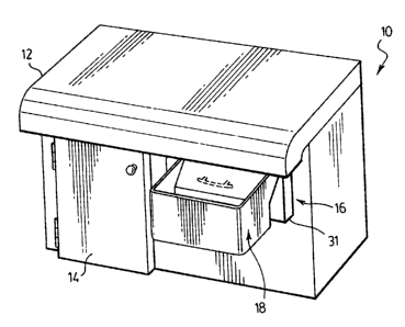
29 [0030] Referring now to the drawings and particularly to Figure 1, a
typical working surface
includes a counter top 12 supported on a cupboard 13 with closures in the form
of a door 14 and
31 a drawer 16. The drawer 16 has a front 32 with an upstanding flange 21. The
counter top 12
21303348.1
-3-
CA 02476169 2004-07-29
1 overhangs the front edge of the cupboard to protect the closures from drips
or the like. A
2 garbage tray 18 is mounted to the front of the drawer 16 so as to project
beyond the edge of the
3 top 12.
4
(0031] The main features of the garbage tray 18 are most apparent in reference
to Figures 2
6 and 3, which show both the side and top views, respectively, of the tray 18
as mounted to a
7 drawer 16. The body of the tray 18 is integrally moulded from a plastic
material and, includes a
8 front wall 34, bottom base 30, sidewalk 36, back wall 26 and open top 28.
The back wall 26 has
9 an upper slopped portion 26a and lower vertical portion 26b to define a
recess as indicated at 27
to accommodate a drawer handle 20 which is fixed to the front 32 of the drawer
16.
11
12 [0032) The tray 18 is detachably mounted on the upstanding flange 21 of the
front 32 of the
13 drawer 16 by way of a lip 22 that projects rearwardly from the upper edge
of the back wall 26
14 and hooks around the upstanding flange 21. The lip 22 is thin so as to
allow the drawer 16 to
close completely, and allow the rear portion of the tray 18 to be positioned
beneath the overhang
16 of the counter top 12. The lip 22 has a degree of flexibility to allow it
to accommodate different
17 thickness of flange 21 as it is used in different locations. The lip 22
grips the flange 2I while
18 allowing the tray 18 to be readily removed and placed in a different
location.
19
[0033] The tray 18 is held substantially in a level horizontal position by way
of a pair of
21 spacers 24. The spacers 24 are attached to the exterior face of the back
wall 26 and extend from
22 this face to rest against the outer face of the front member 32 of the
drawer 16. It will be
23 appreciated that the shape of the back wall 26 may be of any contour while
continuing to extend
24 outwardly to accommodate the presence of a handle 20. Furthermore, the
spacers 24 may be of
any shape, size or orientation while continuing to prop the tray 18, in the
manner described
26 herein.
27
28 [0034) As can been seen most clearly in Figure 3, the spacers 24 are
positioned at spaced
29 locations along the tray 18, between the two side walls 36 so as to avoid
the drawer handle 20.
Also shown in Figure 3, is a typical location for a cupboard door knob 38. It
can be seen that the
31 position of the spacers 24 also accommodates the typical location of a
cupboard door knob 38.
21303348.1
-4-
CA 02476169 2004-07-29
1 This view furthermore shows the nature of the lip 22 that hooks over the
upstanding flange 21 of
2 the front member 32 of the drawer 16. It can be appreciated that the lip 22
may be provided as
3 one continuous piece or provided as shown with two symmetrical members and
any number of
4 spacers 24 may be used as needed in the particular application. It is also
possible to exclude the
spacers 24, particularly if there is no need to prop the tray 18 in a level,
horizontal manner and
6 rely upon the tray 18 resting against the drawer or door handle 20 if
necessary. This is possible
7 due to the slanted and outwardly extending nature of the back wall 26.
8
9 [0035] When in use, the tray is positioned on the drawer front by sliding
the lip 22 over the
flange 21. With the drawer closed, the tray is positioned beneath the edge of
the counter top. In
11 this position the tray 18 collects any unwanted material that is wiped or
swept from the surface
12 of the counter top 12 in the direction of the tray 18 to fall within the
basin of the tray 18. To
13 perform this task most effectively, the drawer 16 must be in a closed
position with the tray 18
14 positioned partially beneath the overhang of the counter top 12. This
creates a continuous
surface to ensure that all of the material being wiped or swept from the
surface of the counter top
16 12 is collected within the tray 18. The tray 18 however, is mounted such
that the drawer 16 may
17 be opened if access to the drawer 16 is required.
18
19 [0036] The tray 18 is mounted by hooking the lip 22 around the upstanding
flange 21 of the
front member 32 of the drawer 16 and allowing the spacers 24 to rest against
the front face of the
21 drawer lb which maintains the tray 18 in a substantially level and
horizontal orientation. The
22 spacers 24 prop the tray 18 away from the drawer handle 20 which allows the
tray 18 to be used
23 on any drawer 16 or cupboard door without the need for additional hardware
such as a bracket or
24 without any modifications such as the removal of a drawer handle 20.
26 [0037] When the tray is full or the preparation finished, the tray may be
removed and taken
27 to the garbage for disposal.
28
29 [0038] The lip 22 may be adjustable as shown in Figure 4. An inner L-shaped
lip 40 is
slideably attached within the upper horizontal member 42 of the back wall 26
and tensioned
31 using a spring 44. This configuration allows the tray 18 to be adjustable
to accommodate
21303348.1
-5-
CA 02476169 2004-07-29
1 drawers 16 and drawer handles 20 of various sizes. It is appreciated that
the lip 22 may be
2 adjustable by means other than that of a spring 44, such as by use of a pin
and a series of holes or
3 any other known method of securing a pair of relative moving members in
multiple positions.
4
[0039] Further modifications can be made to maintain adjustability of the tray
18 to
6 accommodate different configurations of drawer. Making reference now to
Figure 5, the spacers
7 24 may be removable. The rear wall 26 is formed with a pair of slots 52 that
receive a t-shaped
8 removable prop 50. The prop may vary in size to accommodate various drawer
16
9 configurations.
11 [0040] In some situations it may be beneficial to be able to empty the
contents of the tray 18
12 while it remains in its operable position. As illustrated in Figure 8 and
Figure 9, to allow this to
13 occur the tray 18 can be modified to include a drain hole 80 within the
bottom base 30 and a
14 stopper 90 which seals the tray 18 until emptying is required. In a
situation where continuous
quantities of small material is accumulated within the tray 18, the user may
remove the plug 90
16 from the bottom base 30 allowing the contents to drain or if necessary to
be rinsed from the tray
17 18 into a bucket or additional garbage receptacle located beneath the drain
hole 80. It may be
18 appreciated that the stopper 90 may plug the drain hole 80 by being applied
to either the inner or
19 outer surface of the bottom base 30 and is up to the discretion of the
user.
21 [0041] In other situations, it may be desirable to empty the tray by
pouring its contents using
22 a spout 60 as seen most clearly in Figure 6. The material collected in the
tray 18 may be of a
23 desirable kind and could, for example, be vegetables that have been chopped
on the surface of
24 the counter top 12. In this situation, as shown in Figure 14, the side
walls 36 can be of a
transparent material that would allow measuring lines 140 to be marked. The
user may then
26 empty the contents of the tray 18 using the spout 60, when the proper
amount of material is
27 accumulated as indicated by comparison with the measuring lines 140. Also
shown in Figure 6
28 is a set of dividers 62 that can compartmentalize the tray 18 if desired.
This may be especially
29 useful when the tray 18 is used to accumulate desirable material from the
counter top 12. The
dividers 62 may be permanent, but it is most desirable for them to be
removable.
31
21303348.1
-6-
CA 02476169 2004-07-29
1 [0042] Other additional features can be incorporated, especially for use in
a kitchen
2 environment. As see in Figure 7, auxiliary holders can be built in to the
walls of the tray 18.
3 One form could be of a pouch shape 70 to hold large objects such as a
scraper 74. Another form
4 could be of a rack with slots 72 to hold utensils such as knives. It may be
appreciated that these
are only examples of useful auxiliary holders and may exist in various forms
as required by the
6 particular environment and situation. As shown in Figure 1 l, an inner Iedge
110 may be
7 incorporated to accommodate the use of a strainer or filter 112. This may
also be useful in a
8 kitchen environment where unwanted fluids can be strained into the basin of
tile tray 18.
9
[0043] The basic shape of the tray 18 may be modified to incorporate other
additional
11 features depending on the application. As can be seen in Figure 10, the
front wall 100 can be
12 extended to be of a higher profile then the top opening 28 of the tray 18.
A high front wall 100 is
13 beneficial for catching material as it is swept ofd of the working surface
12 towards the opening
14 28 of the tray 18. Referring now to Figure 12 and Figure 13, protrusions
120 of the front wall 34
1 S can act as a handle for transporting or moving the tray 18. Additionally,
modifications to the
16 shape of the bottom base 122, 130 are useful for standing the tray 18 in an
upright position.
17
18 [0044] In another embodiment of the present invention, the tray 18
described herein may
19 comprise of an open top and an open bottom 150 as shown in Figure 15. This
particular
configuration is most useful in an environment where the material being
cleaned from the
21 working surface 12 is of the type that will be discarded. The open bottom
150 allows for a
22 disposable garbage bag 152 to be folded over the top rim 154 of the tray 18
and the remainder of
23 the bag will fall through the open bottom 150. The rim 154 is formed with a
flared skirt 156 and
24 hooks 158 along its forward and side edges to secure the bag to the tray
18. A groove 160 is
formed on the rear edge to accommodate the hag 152 and allow the drawer to
close.
26 [0045] A further embodiment is shown in Figures 16 and 17. A tray 18 has a
sloped front
27 wall 34 that merges smoothly with base 30. The back wall 26 has a pair of
channels 130
28 integrally moulded in the back wall 26 to provide spacers 24. The upper
edge of back wall 26 is
29 inclined to merge with the lip 22.
21303348.1
CA 02476169 2004-07-29
1 [0046] A seal 132 is secured to the lip 22 so as to project upwardly along
the major extent of
2 the lip. The seal 132 is flexible and tapers to its upper tip so as to be
able to conform to the
3 underside of countertop 12. The seal 132 may be formed from a number of
plastics or rubber
4 material and may be integrally moulded with the tray I 8 if preferred.
S (0047] In operation, the lip 22 may engage the top edge of a drawer or door
with the cannels
6 130 abutting the front. As the drawer is closed, the seal engages the
countertop and forms an
7 effective seal to prevent ingress of debris into the drawer.
8 [0048] The tray 18 is contoured to be stackable with similar trays by virtue
of the tapered
9 front wall, sidewalk and channels to facilitate storage and transportation.
As shown in Figure
18, the stackability may be enhanced by the provision of a foot 130, similar
to that shown in
11 Figure 13 to maintain separation of the units.
12
13 [0049] Alternatively, as shown in Figure 19, the skirt 162 can depend from
the rim of front
14 face 34 and sides 26 and the rim of the lower tray in the stack.
16 [0050] As a further alternative, as shown in Figure 20, ribs 164 may be
moulded on the
17 exterior of rear face 26 and on the interior of front face 34 to support
the trays in stacked
18 configuration.
19
[0051) In each embodiment, the tray 18 is positioned to provide a container
beneath the edge
21 of the counter top that does not interfere with the use of the drawer or
cupboard on which it is
22 mounted. It may readily be removed to facilitate storage when not in use or
work at different
23 areas of the counter top.
24
[0052] Although the invention has been described with reference to certain
specific
26 embodiments, various modifications thereof will be apparent to those
skilled in the art without
27 departing from the spirit and scope of the invention as outlined in the
claims appended hereto.
21303348.1
_g_