Note : Les descriptions sont présentées dans la langue officielle dans laquelle elles ont été soumises.
CA 02478624 2004-09-02
WO 03/088325 PCT/US03/03196
GAS DRIVEN PLANETARY ROTATION APPARATUS AND
METHODS FOR FORMING SILICON CARBIDE LAYERS
Field of the Invention
The present invention relates to methods and apparatus for rotating a
substrate and, more particularly, to such methods and apparatus providing gas
driven rotation to the substrate.
Background of the Invention
Silicon carbide (SiC) is increasingly recognized as an effective
semiconductor material for electronic devices. SiC possesses a number of
properties that make it particularly attractive for applications requiring
devices to
operate at high temperature, power and/or frequency. SiC exhibits highly
efficient
heat transfer and is capable of withstanding high electric fields.
It has been demonstrated that hot-wall chemical vapor deposition (CVD)
reactors can provide epitaxial layers of SiC with morphology and doping
superior
to cold-wall systems. See, for example, U.S. Patent No. 5,695,567 to Kordina
et
al., the disclosure of which is hereby incorporated herein by reference. It
has
further been demonstrated that the addition of substrate rotation to a hot-
wall CVD
system may improve both the per cycle capacity of the system and the
uniformity
of the epitaxial layers obtained. U.S. Patent No. 4,860,687 to Frijlink
discloses a
device comprising a flat susceptor rotating parallel to a reference surface.
The
device disclosed therein may be used in a vapor phase epitaxy system.
Summary of the Invention
According to embodiments of the present invention, a gas driven rotation
apparatus for use with a flow of drive gas includes a base member having an
upper
surface, a main platter overlying the upper surface of the base member, and a
satellite platter overlying the main platter. The apparatus is adapted to
direct the
-1-
CA 02478624 2004-09-02
WO 03/088325 PCT/US03/03196
flow of drive gas between the upper surface of the base member and the main
platter such that the main platter is rotated relative to the base member by
the flow
of drive gas. At least a portion of the flow of drive gas is directed from
between
the upper surface of the base member and the main platter to between the main
platter and the satellite platter such that the satellite platter is rotated
relative to the
main platter by the at least a portion of the flow of drive gas.
According to further embodiments of the present invention, a gas driven
rotation apparatus for use with a flow of drive gas includes a base member
having
an upper surface and a main platter having an upper surface and overlying the
upper surface of the base member. At least one generally radially extending,
substantially straight satellite drive channel is formed in the upper surface
of the
main platter. A satellite platter overlies the main platter and the at least
one
satellite drive channel. The apparatus is adapted to direct at least a portion
of the
flow of drive gas through the satellite drive channel to rotate the satellite
platter
relative to the main platter about an axis of rotation.
According to further embodiments of the present invention, a gas driven
rotation apparatus for use with a flow of drive gas includes a base member
having
an upper surface, a main platter overlying the upper surface of the base
member,
and a satellite platter overlying the main platter. The apparatus is adapted
to rotate
the main platter relative to the base member in a first direction. The
satellite
platter is rotated relative to the main platter in a second direction opposite
the first
direction. At least one of the rotation of the main platter and the rotation
of the
satellite platter is driven by the flow of drive gas.
According to method embodiments of the present invention, a method for
rotating an article includes providing a gas driven rotation apparatus
including a
base member having an upper surface, a main platter overlying the upper
surface
of the base member, and a satellite platter overlying the main platter. The
article is
placed on the satellite platter. A substrate is placed on the satellite
platter. A flow
of drive gas is directed between the upper surface of the base member and the
main
platter such that the main platter is rotated relative to the base member by
the flow
of drive gas. At least a portion of the flow of drive gas is directed from
between
the upper surface of the base member and the main platter to between the main
-2-
CA 02478624 2004-09-02
WO 03/088325 PCT/US03/03196
platter and the satellite platter such that the satellite platter is rotated
relative to the
main platter by the at least a portion of the flow of drive gas
According to further method embodiments of the present invention, a
method for rotating an article includes providing a gas driven rotation
apparatus
including a base member having an upper surface, a main platter overlying the
upper surface of the base member, and a satellite platter overlying the main
platter.
The article is placed on the satellite platter. The main platter is rotated
relative to
the base member in a first direction. The satellite platter is rotated
relative to the
main platter in a second direction opposite the first direction. At least one
of the
rotation of the main platter and the rotation of the satellite platter is
driven by a
flow of drive gas.
Objects of the present invention will be appreciated by those of ordinary
skill in the art from a reading of the Figures and the detailed description of
the
preferred embodiments which follow, such description being merely illustrative
of
the present invention.
Brief Description of the Drawings
The accompanying drawings, which are incorporated in and constitute a
part of the specification, illustrate embodiments of the invention and,
together with
the description, serve to explain principles of the invention.
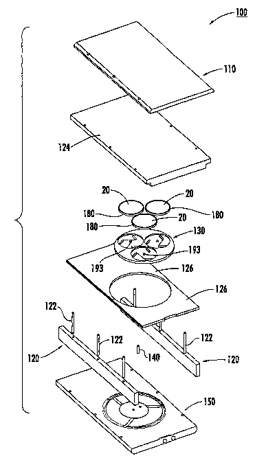
Figure 1 is an exploded, perspective view of a susceptor assembly
according to embodiments of the present invention;
Figure 2 is a perspective view of the susceptor assembly of Figure l;
Figure 3 is a schematic view of a hot-wall CVD system according to
embodiments of the present invention incorporating the susceptor assembly of
Figure l;
Figure 4 is a top plan view of a base member forming a part of the
susceptor assembly of Figure 1;
Figure 5 is an enlarged, fragmentary, top view of the base member of
Figure 4;
Figure 6 is a top plan view of a main platter forming a part of the susceptor
assembly of Figure 1;
-3-
CA 02478624 2004-09-02
WO 03/088325 PCT/US03/03196
Figure 7 is a cross-sectional view of the main platter of Figure 6 taken
along the line 7-7 of Figure 6;
Figure 8 is a cross-sectional view of the main platter of Figure 6 taken
along the line 8-8 of Figure 6;
Figure 9 is a cross-sectional view of the main platter of Figure 6 taken
along the line 9-9 of Figure 6;
Figure 10 is a top plan view of a satellite platter forming a part of the
susceptor assembly of Figure 1;
Figure 11 is a top plan view of the susceptor assembly of Figure 1 wherein
a cover member and side members thereof are removed;
Figure 12 is a cross-sectional view of the susceptor assembly of Figure 1
taken along the line 12-12 of Figure 11 wherein one of the satellite platters
thereof
is omitted for clarity; and
Figure 13 is a top plan view of a susceptor assembly according to further
embodiments of the present invention wherein a cover member and side members
thereof are removed.
Detailed Description of the Preferred Embodiments
The present invention now will be described more fully hereinafter with
reference to the accompanying drawings, in which preferred embodiments of the
invention are shown. This invention may, however, be embodied in many
different
forms and should not be construed as limited to the embodiments set forth
herein;
rather, these embodiments are provided so that this disclosure will be
thorough and
complete, and will fully convey the scope of the invention to those skilled in
the
art. Like numbers refer to like elements throughout.
With reference to Figures 1 and 2, a susceptor assembly 100 according to
embodiments of the present invention is shown therein. The susceptor assembly
100 may be used .in a hot-wall CVD system 10 as shown in Figure 3, wherein the
susceptor 100 is schematically illustrated. With the exception of the
susceptor
assembly 100, the hot-wall CVD system may be of conventional construction and
use. The system 10 includes a quartz tube 12 defining a through passage 14.
The
tube 12 is surrounded by an RF coil 16. The assembly 100 is disposed in the
tube
12. Precursor gases such as silane (SiH4) and propane (C3Hg) are introduced
with
-4-
CA 02478624 2004-09-02
WO 03/088325 PCT/US03/03196
and transported by a carrier of purified hydrogen gas (Hz) into and through
the tube
12. The RF coil 16 inductively heats the susceptor assembly 100 to provide a
hot
zone where the SiC deposition reactions take place. More particularly, a layer
of
SiC is grown on the exposed surfaces of the target wafers 20 (schematically
illustrated in Figure 3). Modifications to the system 10 and the method of
using
the same will be understood by those of ordinary skill in the art upon reading
the
description herein. It will be appreciated that the present invention may be
used in
other types of reactors and with other types of heating devices and
techniques.
The susceptor assembly 100 is adapted to provide planetary rotation of the
several wafers 20 relative to the reactant gas flow and heated portions of the
system 10. More particularly, the susceptor assembly 100 rotates the several
wafers 20 about a common rotational axis L-L (Figure 12) and simultaneously
rotates each wafer about a respective individual rotational axis (e.g:,
rotational axis
Q-Q; Figure 12). Each of these rotational movements is driven by a flow of
drive
1 S gas.
Turning to the susceptor assembly 100 in greater detail, and as best seen in
Figures 1 and 2, the assembly 100 includes a cover member 110, side wall
members 120 and a base member 150 forming a box which is open at an upstream
or entrance end 110A and at an exit or downstream end 110B of the assembly
100.
The members 110, 120, 150 are located by fasteners 122. A passage 102 extends
fully through the assembly 100 from the end 110A to the end 110B. An upper
liner 124 and a pair of lower liners 126 are mounted on the cover member 110
and
the base member 150, respectively. Preferably, the liners 124, 126 are mounted
and constructed as described in U.S. Patent Application Serial No. 10/017,492,
titled Induction Heating Devices and Methods for Controllably Heating an
Article,
filed October 30, 2001, the disclosure of which is hereby incorporated herein
by
reference in its entirety. A main platter 130 is disposed in the passage 102
and is
mounted for rotation about a pin or spindle 140. The platter 130 is preferably
disk-
shaped as illustrated. Three satellite platters 180 are mounted for rotation
on the
main platter 130 about respective spindle posts 193. The wafers 20 (Figure 1)
are
mounted on the satellite platters 180.
With reference to Figures 1, 4, 5 and 12, the base member 150 has an
upper surface 151A. An exhaust passage 154 is formed in the base member 150
-5-
CA 02478624 2004-09-02
WO 03/088325 PCT/US03/03196
adjacent the exit end 110B and terminates in an opening 154A. The base member
150 further includes a platter mounting portion 160 formed in the upper
surface
151A. A gas supply passage 170 is formed in the base member 150 and fluidly
communicates with a threaded inlet opening 172 and an outlet opening 174 in
the
portion 160. A connecting passage 176 provides fluid communication between the
portion 160 and the passage 154, as discussed below.
The platter mounting portion 160 is preferably a recess or depression as
illustrated. The portion 160 has a relatively deep, circumferential, endless
channel
164, an inner or central recess 162 and a plurality of straight i.e.,
rectilinear),
generally radially extending main drive channels 168 which, in combination,
form
a plurality of landings 166 therebetween. Preferably, the channels 168 do not
deviate from straight by more than standard, low cost manufacturing processes
permit (typically on the order of 0.001 inch per inch of channel length). The
main
drive channels 168 are preferably symmetrically positioned with equidistant
spacing about the central recess 162. More or fewer main drive channels 168
may
be provided. The central recess 162 is preferably circular and the channel 164
and
the central recess 162 are preferably substantially concentric as shown.
A spindle recess 163 is formed in the center of the central recess 162. The
opening 174 is formed in the central recess 162 at a position offset from the
center
of the central recess 162.
The outer vertical wall 164B of the channel 164 extends up to the
surrounding portion of the upper surface 151A. The inner vertical wall 164A of
the channel 164 extends up to the landings 166. The connecting passage 176 has
an upper opening in the bottom wall of the channel 164 and a lower opening at
the
passage 154.
The drive channels 168 each extend from an entrance end 168A to an exit
end 168B. The entrance ends 168A each intersect the central recess 162 and the
exit ends 168B each intersect the channel 164. The drive channels 168 extend
at
an angle with respect to a central axis of rotation L-L (see Figure 12). More
particularly, and with reference to Figure 5, each drive channel 168 defines a
central channel axis N-N that extends through the center of the channel 168.
The
axis N-N is offset from i.e., does not intersect) the axis of rotation L-L
(which, in
Figure 5, extends directed out of the paper through the center of the spindle
recess
-6-
CA 02478624 2004-09-02
WO 03/088325 PCT/US03/03196
163). A straight reference line M-M intersects the channel axis N-N at the
exit end
168B of the drive channel 168 and is tangential to a reference circle defined
by the
inner vertical wall 164A of the channel 164. The channel axis N-N and the
reference line M-M define an included angle P therebetween. The angle P is
less
than 90 degrees. More preferably, the angle P is between about 35 and 75
degrees.
Most preferably, the angle P is between about 45 and 65 degrees.
Preferably, the drive channels 168 have a width of between about 0.5 and
0.1 inch. Preferably, the drive channels 168 have a depth of between about
0.002
and 0.020 inch.
Preferably, the outer vertical wall 164B of the channel 164 and the outer
peripheral edge 134 of the platter 130 define a gap therebetween having a
width of
between about 0.100 and 0.010 inch. Preferably, the channel 164 has a width of
between about 0.250 and 0.050 inch and a depth below the landings 166 of
between about 0.100 and 0.020 inch. The lengths J of the drive channels 168
and
the diameter K of the inner vertical wall 164A (Figure 4) will depend on the
size
of the main platter 130.
Preferably, the landings 166 are vertically recessed below the top surface
151A a distance that is approximately the same as the thickness of the platter
130.
Preferably, the central recess 162 is vertically recessed from the landings
166 a
distance of between about 0.100 and 0.010 inch. Preferably, the central recess
162
has a diameter I (Figure 4) of between about 1.00 inch and 50% of the main
platter
diameter.
A drive gas supply device 171 is connected to the threaded inlet opening
172 for fluid communication with the passage 170. The gas supply device 171 is
operable to force a flow of pressurized drive gas into the gas supply passage
170.
The drive gas supply device 171 may be alternatively or additionally connected
to
the drive gas exhaust passage 154 to draw the drive gas from the base member
150.
Suitable gas supply devices include Gilmont Instruments mass flow controllers
available from Barnant Co. of Barrington, Illinois. Preferably, the drive gas
is non-
reactive. More preferably, the drive gas is noble, particularly argon or
helium.
Most preferably, the drive gas is argon. Other suitable drive gases include
H2.
As best seen in Figures 11 and 12, the main platter 130 overlies the platter
mounting portion 160 (Figure 4) of the base member 150. With reference to
_7_
CA 02478624 2004-09-02
WO 03/088325 PCT/US03/03196
Figures 1, 6-9 and 12, the main platter 130 is substantially circular and has
an
upper surface 131A, an opposing lower surface 131B, and an outer peripheral
edge
134. A spindle recess 133 is formed in the lower surface 131B. The lower
surface
131B is preferably substantially smooth without any grooves or protrusions
other
than the spindle recess 133.
As best seen in Figures 6-9, three satellite pockets 190 are formed in the
upper surface 131A of the main platter 130. A spindle post 193 extends
upwardly
from each pocket 190. Preferably, each pocket 190 has a depth A (Figure 7) of
between about 0.1 and 0.3 inch. Preferably, each pocket 190 has a diameter B
(Figure 7) that is between about 0.005 and 0.2 inch greater than the diameter
of the
intended wafer. The pockets 190 are preferably positioned substantially
equidistantly about the center i.e., the axis L-L) of the main platter 130.
Three arrays 191 of passages and channels are located in each of the
pockets 190, respectively. The arrays 191 are preferably substantially
identical and
symmetrically arrayed and oriented about the center of the platter 130.
Accordingly, only one of the arrays will be described in detail below, it
being
understood that this description applies to the other two arrays 191 as well.
The array 191 includes three satellite drive channels 192A, 192B, 192C
formed in the upper surface 131A of the main platter 131 within the recesses
190.
A feed passage 194A extends fully through the platter 130 from the lower
surface
131B to the upper surface 131A and fluidly intersects the drive channel 192A.
A
second feed passage 194B extends fully through the platter 130 from the lower
surface 131B of the upper surface 131A and fluidly intersects the drive
channel
192B. A feed channel 196 formed in the upper surface 131A extends between and
fluidly intersects each of the drive channel 192B and the drive channel 192C
such
that the feed passage 194B is fluidly connected to the drive channel 192C by
the
feed channel 196.
Preferably, each drive channel 192A, 192B, 192C has a depth C (Figure 7)
of between about 0.002 and 0.020 inch, a length D (Figure 6) of between about
20
and 80 percent of the wafer diameter, and a width E (Figure 6) of between
about
0.1 and 0.5 inch. Preferably, each feed channel 196 has a depth F (Figure 9)
of
between about 0.006 and 0.080 inch, a length G (Figure 6) of between about 25
_g_
CA 02478624 2004-09-02
WO 03/088325 PCT/US03/03196
and 100 percent of the wafer diameter, and a width H (Figure 6) of between
about
0.02 and 0.3 inch.
Preferably, and as illustrated, each of the satellite drive channels 192A,
192B,192C is substantially straight (i.e., rectilinear). However, the channels
192A, 192B, 192C may be otherwise shaped (e.g_, curvilinear or arcuately
shaped).
As best seen in Figure 12, the main platter 130 is mounted over and
partially within the mounting portion 160. In Figure 12, the main platter 130
is
shown in a floating or levitated position as discussed below. The lower end of
the
spindle 140 is disposed in the recess 163 and the upper end of the spindle 140
is
disposed in the recess 133. The central axis of the spindle 140 defines the
axis of
rotation L-L, which is orthogonal to the upper surface 131A of the main
platter
130. The recess 133 is sized such that the main platter 130 can slide freely
vertically up and down along the spindle 140 and such that the main platter
130
can rotate freely about the spindle 140 about the axis L-L.
With reference to Figures 1, 10 and 12, the satellite platters 180 each
include an upwardly opening wafer pocket 182 and a surrounding wall 184. Each
pocket 182 is adapted to hold one of the wafers 20. The outer diameter T of
the
satellite platters 180 is preferably between about 0.005 and 0.2 inch less
than the
diameter of the pockets 190. A spindle recess 186 is formed in the lower
surface
of each satellite platter 180 to receive a corresponding one of the spindle
posts 193
such that the platters 180 may slide freely up and down the posts 193.
The members 110, 120,150, the main platter 130, and the spindle 140 are
preferably formed of high purity graphite with a fully surrounding coating of
dense
SiC (i.e., impervious and having 0% porosity). Alternatively, the main platter
130
may be formed of solid SiC or a solid SiC alloy. Alternatively, the main
platter
130 may be formed of graphite coated with TaC. The liners 126 are preferably
formed of graphite coated with SiC or a refractory metal carbide such as TaC.
The satellite platters 180 may be formed of graphite impregnated with
carbon. Alternatively, the platters 180 may be formed of graphite impregnated
with carbon coated with SiC or TaC or unimpregnated graphite coated with SiC
or
TaC. Alternatively, the platters 180 may be formed of solid, uncoated SiC or
SiC
coated with TaC.
-9-
CA 02478624 2004-09-02
WO 03/088325 PCT/US03/03196
The susceptor assembly 100 may be used in the following manner.
Initially, the platter 130 is disposed in the platter mounting portion 160
such that
the platter 130 rests on the landings 166. The satellite platters are placed
in the
pockets 190. The wafers 20 are placed in the pockets 182 of the satellite
platters
180. Figures 11 and 12 show the assembly 100 in use but with the wafers 20
being omitted for clarity. In Figure 12, the left side satellite platter 180
is also
omitted for clarity.
The gas supply device 171 is then actuated. The gas supply device 171
forces the drive gas through the inlet opening 172, the passage 180 and the
outlet
opening 174 as indicated by the arrows in Figure 12. The drive gas enters the
plenum formed by the central recess 162 and the overlying platter 130 from the
outlet opening 174. The drive gas in the plenum is pressurized until the
differential
between the drive gas pressure and the ambient pressure (i.e., acting on the
upper
surface 131A of the platter 130) overcomes the gravitational force on the
platter.
In this manner, the pressurized drive gas forces the platter 130 upwardly
(i.e., in
the direction U; Figure 12).
Once the platter 130 is levitated, a first portion of the drive gas flows
outwardly from the central recess 162 between the platter 130 and the portion
160
of the base member 150 and into the channel 164 as indicated by arrows in
Figure
4. At least some of this first portion of the drive gas flows from the central
recess
162 to the channel 164 through the drive channels 168 as indicated by the
arrows
in Figure 4. Some of the drive gas exits the channel 164 through the
connecting
passage 176 and is exhausted from the base member 150 through the passage 154.
Some of the drive gas may exit the channel 164 through the gap between the
peripheral edge 134 and the outer vertical wall of the channel 164.
Some of the drive gas provided through the central recess 162 flows from
the central recess 162 to the gap between the base member 150 and the lower
surface 131B of the main platter 130. Some of this drive gas flows into the
channel 164 and is exhausted through the passage 154 or about the peripheral
edge
134 of the main platter.
In order to levitate and rotate the satellite platters 180, a second portion
of
the drive gas provided through the central recess 162 flows from the central
recess
162, between the base member 150 and the lower surface 131B of the main
platter
-10-
CA 02478624 2004-09-02
WO 03/088325 PCT/US03/03196
130, up through each of the feed passages 194A,194B, and into the pockets 190.
The drive gas from each feed passage 194A flows radially outwardly (relative
to
the rotational axis of the respective spindle post 193) through the adjacent
drive
channel 192A between the drive channel 192A and the lower surface of the
overlying satellite platter 180, and out from the pocket 190 about the
periphery of
the platter 180.
A portion of the drive gas from each feed passage 194B flows radially
outwardly along the adjacent drive channel 192B between the drive channel 192B
and the platter 180. A further portion of the drive gas from the feed passage
194B
flows through the feed channel 196 to the associated drive channel 192C, and
through the drive channel 192C.
Additional portions of the drive gas from the feed passages 104A, 104B
may flow radially outwardly between the pockets 180 and the satellite platters
180
and exhaust about the peripheries of the satellite platters 180 without
flowing
through the drive channels 192A,192B,192C or the feed channels 196.
The portions of the drive gas supplied through the feed passages 194A,
194B force the satellite platters 180 upwardly (i.e., in the direction U) and
levitate
the platters 180 above the main platter 130.
The drive gas is continuously forced through the assembly 100 at a rate and
pressure sufficient to maintain the main platter 130 in a levitated position
above the
landings 166 and to maintain the satellite platters 180 in a levitated
position above
the main platter 130 as shown in Figure 12. The levitation height of the main
platter 130 may be controlled by selection of the width and depth of the drive
channels 168, the diameter of the central recess 162, the pressure of the
drive gas
between the platter 130 and the portion 160, and the drive gas flow rate. The
levitation height of the satellite platters 180 may be controlled by selection
of the
width and depth of the drive channels 192A, 192B,192C, the diameters of the
pockets 190 and the satellite platters 180, and the drive gas flow rate.
Additionally, the drive gas flow through the drive channels 168 is viscously
coupled to the lower surface 131B of the platter 130. Because of the angled
orientation of the drive channels 168, the platter 130 is thereby rotated
about the
axis L-L in a clockwise direction R (Figure 11) by the flowing gas. The rate
of
rotation may be controlled by selection of the angle P (Figure 12) defined by
the
-11-
CA 02478624 2004-09-02
WO 03/088325 PCT/US03/03196
drive channels 168 as well as the depth, width and length of the drive
channels
168. Preferably, the rate of rotation of the platter 130 is between about 3
and 60
revolutions per minute (rpm).
Furthermore, the drive gas flow through the drive channels 192A, 192B,
192C is viscously coupled to the lower surfaces 181 of the satellite platters
180.
Because of the angled orientation of the drive channels 192A, 192B, 192C, the
satellite platters 180 are thereby rotated about the rotational axes defined
by the
spindle posts 193 (e.~., the rotational axis Q-Q as shown in Figure 12) in a
counterclockwise direction S (Figure 11) by the flowing gas. The rate of
rotation
may be controlled by selection of the angle and/or shape of the drive channels
192A,192B, 192C as well as the depth, width and length of the drive channels
192A, 192B, 192C. Moreover, the rate of rotation of the satellite platters 180
may
be controlled by selection of the flow rate of the drive gas. Preferably, the
rate of
rotation of the satellite platters 180 is between about S and 60 revolutions
per
minute (rpm).
The assembly 100 provides a number of advantages. The planetary rotation
may provide a more uniform temperature environment as between respective
wafers 20 and across each wafer 20. The planetary rotation may provide more
uniform exposure of the wafers to the flow of process gas.
The use of common supplied drive gas flow to levitate and drive the
rotation of both the main platter 130 and the satellite platters 180 may
provide a
less complex construction. The simplicity of the construction may provide for
more consistent and controllable operation. By using a single gas flow, the
cost
and complexity of additional gas flow controls, valves, etc. can be reduced or
eliminated. The assembly 100 may be designed such that very little or no
additional drive gas need be supplied as compared to a simple rotation device
(i.e.,
wherein only the main platter rotates).
The provision of straight drive channels 168 may provide certain
advantages. Across a substantial range of drive gas flow rates, the spin rate
of the
platter 130 may be maintained at a given rate substantially independent of the
drive
gas flow rate. This allows for greater consistency (i.e., repeatability) in
processing.
Additionally, this behavior allows for adjustment of the platter levitation
height H
(Figure 12) by altering the drive gas flow rate.
- 12-
CA 02478624 2004-09-02
WO 03/088325 PCT/US03/03196
Moreover, the provision of straight drive channels 168 may allow for
improved control of the levitation height and rate of rotation of the
satellite platters
180. Because the spin rate of the main platter 130 is independent of the drive
gas
flow rate (in a suitable range), the drive gas flow rate can be increased and
decreased to in turn increase and decrease the spin rate and/or levitation
height of
the satellite platters 180 without significantly altering the spin rate of the
main
platter 130. As wear or deposits occur during normal use, the drive gas flow
can
be increased to levitate the main platter 130 and/or the satellite platters
180 at
greater heights without significantly altering their rotation speeds.
The provision of straight satellite drive channels 192A, 192B, 192C may
also allow improved control of the satellite platters 180. The drive channels
192A,
192B, 192C may be configured such that, across the desired range of drive gas
flow rates, the spin rate of the satellite platters 180 may be maintained
substantially
independent of the drive gas flow rate. This may allow for greater consistency
and/or for adjustment of the levitation height X (Figure 12) by altering the
drive
gas flow rate.
The provision of counter-rotation between the main platter 130 and the
satellite platters 180 may provide certain advantages as well. By counter-
rotating,
the differential between the rates of travel of different locations on the
wafers with
respect to the remainder of the susceptor assembly 100 and with respect to the
flow
of process gas is reduced. Furthermore, the counter-rotation may provide
conservation of angular momentum that tends to cause the satellite platters
180 to
continue rotating. This effect may cause the rotation of the satellite
platters 180 to
assist in restarting or accelerating rotation of the main platter 130 in the
event the
main platter 130 is stopped or slowed, and vice versa. Additionally, the
induced
angular momentum alone acting on the satellite platters 180 may be sufficient
to
cause the satellite platters 180 to rotate counter to the main platter 130
once the
satellite platters 180 are levitated such that, according to some embodiments
of the
present invention, the satellite drive channels may be omitted.
The susceptor assembly 100 may be modified in various ways in
accordance with the present invention. For example, the assembly 100 may be
adapted such that the main platter 130 and the satellite platters 180 rotate
in the
same direction. A different number or configuration of satellite platters 180
may
-13-
CA 02478624 2004-09-02
WO 03/088325 PCT/US03/03196
be provided. The central recess 162 and/or the pockets 190 may be omitted, in
which case the respective drive gas feed passages 174, 194A, 194B are
preferably
replaced with one or more feed passages positioned symmetrically with respect
to
the rotational axis (axes) of the main platter or the satellite platters. The
satellite
platters 180 may be adapted to each hold more than one wafer. As noted above,
the satellite drive channels (~, the channels 192A, 192B, 192C) may be
differently shaped (e~, non-straight). Multiple gas flows may be used such
that
separate i.e., mutually exclusive) gas flows are used to drive the main
platter and
the satellite platters.
It is desirable to use argon (Ar) or like gases (e.~., other noble gases) as
the
drive gas because such gases are less likely than H2 gas to pick up impurities
such
as boron (B), aluminum (Al), titanium (Ti), chromium (Cr), and vanadium (V)
from the graphite, for example, and redeposit these impurities, for example,
onto
the wafer surface. However, the thermal conductivity of Ar gas is
substantially
less than that of H2 gas. As a result, Ar gas present in the reactant gas flow
through the tube 12 (Figure 3) may slow the transfer of heat to the reactants,
thereby creating irregularities in the temperature profile of the reactant gas
flow.
The assembly 100 may provide for exhaust of the drive gas with only minimal
introduction of the drive gas into the reactant stream so that Ar gas may be
used as
the drive gas without jeopardizing the reactant stream temperature profile.
As described above, the drive gas preferably flows from an inner recess
e(~. ., the inner recess 162) to an outer channel (e.~., the outer channel
164).
However, the direction of flow may be reversed (i.e., the drive gas being
supplied
through the passage 154 and exhausted through the passage 170).
Susceptor assemblies according to the present invention may incorporate
any of the features and aspects as described in U.S. Patent Application Serial
No.
09/756,548, filed January 8, 2001 and titled Gas-Driven Rotation Apparatus and
Method for Forming Silicon Carbide Layers, the disclosure of which is hereby
incorporated herein by reference in its entirety.
With reference to Figure 13, a susceptor assembly 200 according to further
embodiments of the present invention is shown therein. The assembly 200
differs
from the assembly 100 only in that each satellite platter 280 thereof includes
a
plurality of wafer pockets 282 formed therein. Accordingly, a plurality of
wafers
- 14-
CA 02478624 2004-09-02
WO 03/088325 PCT/US03/03196
20 may be rotated on a common satellite platter 280 about both the rotational
axis
of the main platter 230 and the rotational axis of the respective satellite
platter 280.
The foregoing is illustrative of the present invention and is not to be
construed as limiting thereof. Although a few exemplary embodiments of this
invention have been described, those skilled in the art will readily
appreciate that
many modifications are possible in the exemplary embodiments without
materially
departing from the novel teachings and advantages of this invention.
Accordingly,
all such modifications are intended to be included within the scope of this
invention as defined in the claims. Therefore, it is to be understood that the
foregoing is illustrative of the present invention and is not to be construed
as
limited to the specific embodiments disclosed, and that modifications to the
disclosed embodiments, as well as other embodiments, are intended to be
included
within the scope of the appended claims. The invention is defined by the
following claims, with equivalents of the claims to be included therein.
-15-