Note : Les descriptions sont présentées dans la langue officielle dans laquelle elles ont été soumises.
CA 02480685 2004-09-27
WO 03/081995 PCT/EP03/03135
Filtration Devices
Technical Field
The present invention relates to aquarium and/or pond filter devices and
methods of using
such devices.
Background of the Invention
Aquariums have long been popular for keeping and displaying fish, both fresh
and saltwater
varieties. However, the recreation of freshwater or saltwater environments in
the self contained
systems of home aquariums has presented considerable difficulties. Initially a
good water source
must be obtained for the start of the aquarium. Additionally, there's the
task, of maintaining the
water quality and dealing with waste materials either i) excreted by the
aquatic specimens, ii) formed
by the natural decomposition by bacteria of plant, animal tissues and food, or
iii) resulting from
foreign contamination of the aquarium environment. This task becomes even more
important with
saltwater environments, which must maintain many delicate balances including
pH and salinity.
It is generally understood that in maintaining the health and vitality of the
animals confined
to an aquarium, provision must be made for continuous filtration and
recirculation of the aquarium
water. A number of differently configured aquarium filter systems have been
devised in an attempt
to meet this need. One such system is the external aquarium filter in which a
filter housing is
located outside the aquarium tank and positioned such that the aquarium water
is drawn up from the
aquarium and into the filter by means of external tubes or tubular extensions.
A typical external filter system consists of an electrically powered pump,
intake and return
lines or tubes, a filter housing containing and a filter medium such as
activated charcoal overlaid
with one or more layers of synthetic filter material. As water is siphoned out
of the aquarium tank
via an inlet tube, it moves through the filter housing inlet chamber into the
central housing chamber
where it passes through the filter medium into the housing outlet chamber and
is pumped back into-~.
the aquarium via the return line.
Although the external filter device is generally adequate for providing
mechanical filtration,
external aquarium filter systems are usually large and bulky. Additionally,
the presence of such
additional components as intake and return lines (or tubing) tends to create
bulkiness and increases
the risk of clogging and/or mechanical breakdown.
Another type of aquarium filter system presently in use is the undergravel
aquarium filter,
specifically designed for placement within the aquarium tank. This type of
system is. comprised of
inlet and outlet tubes, a pumping device, a means for aerating the aquarium
water, and a filter
housing composed of inlet and outlet chambers where the outlet chamber
contains a filter medium
such as activated charcoal. Water from the aquarium is pumped through the
inlet tube to outlet
CONFIRMATION COPY
CA 02480685 2004-09-27
WO 03/081995 PCT/EP03/03135
2
chamber through and exits to the aquarium tank via the outlet tube.
One problem inherent in the undergravel aquarium filter concerns its size.
Since such a
system is dimensionally configured so as to be unobtrusive when placed within
the aquarium tank,
its filter housing is relatively small. Therefore, the volume of filter
material contained within the
housing is generally not sufficient to provide adequate mechanical filtration.
Another problem with
this type of system concerns the location of the filter. Because the filter is
positioned underwater
within the aquarium tank, the filter housing must be physically separated from
the system and
removed from the aquarium tank to accomplish cleaning of the filter; a
procedure which disturbs the
aquarium environment and interrupts the entire filtering process.
Accordingly, it would be advantageous to provide aquarium filters which are
small enough
in size and number of components so as not to be "large and bullcy", yet still
provide convenience of
handling and adequate mechanical filtration capacity. It is, therefore, an
object of the present
invention to provide filtration devices which avoid the aforementioned
problems.
Another aspect of the present invention is to provide relatively small sized
filtration devices
for use in a variety of different sized aquariums.
(Still another aspect of the present invention is to provide tubeless
filtration devices.
Yet another aspect of the present invention is to provide tubeless filtration
devices which
reduce or eliminate premature overflow of the mechanical filter chamber and/or
filtration device
housing. .
These and other aspects will become readily apparent from the detailed
description which
follows.
Summary of the Invention
The present invention relates to tubeless filter devices, comprising:
a) a mechanical filtration chamber, preferably in the form of a cylindrical or
substantially cylindrical container having a latitudinal cross-section of
curvilinear
shape, containing at least one mechanical filter for filtering water, the
mechanical
filtration chamber having a spillway through which filtered water exits the
mechanical filtration chamber back to, for example, an aquarium;
b) a water flow pump mechanism having inflow port and an outflow port in fluid
flow communication with the mechanical filtration chamber for drawing
contaminated water from a reservoir, such as an aquarium, through the inflow
port so as to pump the water into the mechanical filtration chamber through
the
outflow port; and
CA 02480685 2004-09-27
WO 03/081995 PCT/EP03/03135
3
c) optionally, a positioning mechanism adjustably attached to the housing for
positioning the filter apparatus on or at the surface of the aquarium water
such
that the water pump mechanism can receive aquarium water without the need for
tubes or tubular extensions.
The present invention further relates to methods of filtering aquarium or pond
water by
using the filtration devices described herein.
The term "tubes or tubular extensions", as used herein, refers to tubes or
tubular components
used as external connections or attachments for transporting water to or from
filtration devices, more
specifically aquarium filtration devices, and preferably tubes or tubular
extensions which are at least
1 inch, more preferably at least 0.5 inches in length.
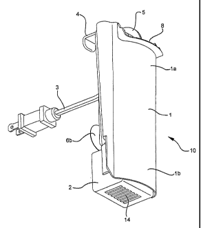
Brief Description Of The Drawings
The following FIGURES represent one particular embodiment of the present
invention.
FIG. 1 is a perspective view of the filtration device of the present
invention;
FIG. 2 is a rear perspective view of the filtration device of the present
invention;
1 S FIG. 3 is an exploded perspective view of the filtration device of the
present invention;
FIG. 4 is a top plan.view of the filtration device of the present invention;
FIG. 5 is a sectional view of the inside of the filtration device housing of
the present
invention taken along lines 5-5 of FIG. 4;
FIG. 6 is a sectional view of the inside of the filtration device housing of
the present
invention talon along lines 6-6 of FIG. 4, showing the directional flow~f
water in the presence of
a Turbulence Reducer component;
FIG. 7 is a sectional view of the inside of the filtration device housing of
the present
invention taken along lines 6-6 of FIG. 4, showing the directional flow of
water in the absence of a
Turbulence Reducer component;
FIG. 8 is a rear view of the filtration device of the present invention;
FIG. 9 is a side view of the filtration device of the present invention.
DescriQtion Of A Disclosed Embodiment
Referring now to FIGS. 1-9, there is shown a filtration device assembly
designated
generally by the numeral 10. The assembly comprises an outer housing 1, having
an upper section
CA 02480685 2004-09-27
WO 03/081995 PCT/EP03/03135
4
la which forms filter chamber 17 and a lower section lb which extends beyond
the lower boundary
of filter chamber 17. The housing 1 is, preferably, in the form of a
cylindrical or substantially
cylindrical container having a latitudinal cross-section of curvilinear shape,
preferably a latitudinal
cross-section of elliptical or oval shape. In the described embodiment, the
filtration device is
supported on the aquarium ZO by an adjustable hanging mechanism which is
adjustably attached to
the housing 1 via prong 12. The hanging mechanism can take the form of a hook
4 (having
adjustable attachment slots 25a and 25b) or, optionally, suction cup 6a.
Additional support can by
provided by, optionally, incorporating at least one other suction cup 6b.
Water from the aquarium is brought into the aquarium filter using flow pump 2
having
inflow port 14 and outflow port 16. The flow pump Z is positioned in fluid
flow communication
with filter chamber 17 and, preferably, shielded by lower section 1b. In one
embodiment, the
filtration device is positioned in a aquarium 20 such that the flow pump 2 is
below or touching the
surface of the aquarium water at inflow port 14. The flow pump 2 comprises
power stator motor 15
and an impeller or an impeller assembly 11 rotatably attached or in rotatable
association with the
motor 15 for driving the flow pump 2.
When the power stator motor 15 is powered (e.g., electrically via power cord 3
in cord
holder 5), impeller 11 within the flow pump 2 is caused to rotate which, in
turn, causes aquarium
water to be drawn from the aquarium tank through inflow port 14 and into flow
pump 2. A flow
control switch 13 can be, optionally, incorporated onto water flow pump 2 for
adjusting the amount
of water drawn into the flow pump 2. The water drawn into the flow pump 2
passes by the impeller
11, through outflow port 16 and into mechanical filtration chamber 17.
Contained within the mechanical filtration chamber 17 is a means for the
mechanically
filtering the aquarium water, typically in the form of filter cartridge 7.
Filtration is performed as the
aquarium water flows directionally through the filter cartridge 7 as
illustrated in Fig. 6.
~, The filter cartridge 7 may consist of non-woven synthetic resin fibers
and/or a coarse
sponges. The Bio Bags filter is an example of a filter cartridge that may be
used. The Bio Bags'
can also hold a quantity of activated carbon to effect chemical as well as
mechanical filtration.
Nonwoven synthetic resin fibers are preferred for use herein. Without being
limited by theory, it is
believed that the resin fibers, in view of their large surface area, provide a
medium for biological
filtration by creating an environment conducive for bacterial growth. In an
aquarium, biological
filtration is important since it serves to rid the tank of (or nitrify) toxic
ammonia.
Bio Bag filters are described in detail in US Patents 4,783,258 and 5,053,125,
both of which
are herein incorporated by reference in their entirety.
Optionally, turbulence reducer 9 can be incorporated in fluid flow
communication with flow
pump 2 at outflow port 16 to improve the directional flow of the water through
filter cartridge 7. In
one embodiment, the turbulence reducer 9 can take the form of a water flow
diverter component.
CA 02480685 2004-09-27
WO 03/081995 PCT/EP03/03135
This improvement in directional water flow results primarily from the
reduction andlor prevention of
water turbulence inside the housing which, in turn, reduces and/or prevents
aquarium water from
prematurely flowing up and over filter cartridge 7 (See FIG. 7). Without being
limited by theory,
water overflowing the top of filter cartridge 7 typically signals the need for
cartridge replacement
5 since clogged filters tend to force water up and over the filter cartridge 7
instead of through the filter
cartridge 7. Preventing or reducing premature overflow (i.e., in the absence
of a clogged filter
cartridge) of the filter cartridge 7 by incorporating turbulence reducer 9
can, therefore, aid in
properly determining the useful life of filter cartridges. In one embodiment,
turbulence reducer 9 is
in the form of a water diverter component.
After passing through the mechanical filtration chamber I7, the water passes
via a spillway
8 back into the aquarium. Spillway 8 directs the water away from the filter in
such a way as to
produce a "waterfall" affect. Without being limited by theory, it is believed
that such an affect
improves the agitation of the aquarium water such that gas exchange is
increased and the
oxygenation of the aquarium water is improved.
It will be understood that each of the elements described above, or two or
more together,
may also fmd a useful application in other types of constructions differing
from the types described
above.
While the invention has been illustrated and described as embodied in a filter
for aquariums,
it is not intended to be limited to the details shown, since various
modifications and structural
changes may be made without departing in any way from the spirit of the
present invention.
Without further analysis, the foregoing will so fully reveal the gist of the
present invention
that others can, by applying current knowledge, readily adapt it for various
applications without
omitting features that, from the standpoint of p~,rior art, fairly constitute
essential characteristics of
the generic or specific aspects of this invention.