Note : Les descriptions sont présentées dans la langue officielle dans laquelle elles ont été soumises.
CA 02481487 2007-01-08
WO 03/0864 87 PCT/US03/10358
ELECTRICAL EVAPORATOR INCLUDING
FAN AND LOUVER STRUCTURE
BACKGROUND OF THE INVENTION
1. Field of the Invention
[0002] The present invention relates generally to an electrical evaporator for
use with
liquid formulations containing a chemical active such as an insecticide, a
fragrance,
an odor eliminator, or the like, and, in particular, to an electrical
evaporator including
a fan and a Iouver structure that helps to achieve a beneficial distribution
of the
chemical active within a surrounding environment, such as a room.
CA 02481487 2004-10-06
WO 03/086487 PCT/US03/10358
-2-
2. Description of the Related Art
[00031 Plug-in electrical evaporators for dispersing chemical actives such as
insecticides and fragrances are well known in the art. For the most part,
however,
these known evaporators fail to achieve an optimal distribution of the
chemical active
within their surrounding environment. Insecticides, for example, should be
concentrated in areas where insects are most likely to come into contact with
a
person's skin. Fragrances, on the other hand, should be most concentrated at
nose
level. We have found that known plug-in evaporators generally undersaturate
the
"living areas" of a room where the chemical active is most likely to come in
contact
with a person's skin or nose, and oversaturate the non-living areas of a room,
such as
the floor, ceiling, and walls. This results in a waste of chemical active and
a decrease
in the overall effectiveness of the evaporator.
SUMMARY OF THE INVENTION
[00041 The present invention provides an electrical evaporator that produces a
beneficial distribution of the chemical active within a surrounding
environment.
[0005] According to one aspect of the invention, an evaporator, for use with a
bottle
containing a substance to be evaporated and a wick that has its lower portion
disposed
within the bottle and its upper portion protruding from the bottle, inchides
(i) a
CA 02481487 2004-10-06
WO 03/086487 PCT/US03/10358
-3-
housing for retaining the bottle, (ii) a fan, disposed within the housing, for
creating an
airstream, and (iii) a louver structure, disposed downstream of the fan, for
directing
the airstream created by the fan upwardly and away from the upper portion of
the
wick.
[0006] In another aspect, the present invention relates to an evaporator
including (i) a
bottle containing a substance to be evaporated, (ii) a wick, having a lower
portion
disposed within the bottle and an upper portion protruding from the bottle,
for
drawing the substance to be evaporated from the bottle toward the upper
portion of
the wick, (iii) a housing in which the bottle is retained, (iv) means, within
the housing,
for creating an airstream, and (v) means for directing the airstream upwardly
and
away from the upper portion of the wick.
[0007] In still another aspect, the present invention relates to a plug-in
evaporator for
dispersing a chemical active into a surrounding environment. The evaporator
includes
(i) a bottle containing a liquid formulation including at least one chemical
active, (ii) a
wick, having a lower portion disposed within the bottle and an upper portion
protruding from the bottle, for drawing the liquid formulation fiom the bottle
toward
the upper portion of the wick, (iii) a housing in which the bottle is
detachably
retained, (iv) an electrical heating device, disposed within the housing at a
position
proximate to the upper portion of the wick, for enhancing evaporation of the
liquid
formulation from the upper portion of the wick, (v) a fan, disposed within the
CA 02481487 2004-10-06
WO 03/086487 PCT/US03/10358
-4-
housing, for creating an airstream that entrains the evaporated liquid
formulation, and
(vi) an electrical plug, extending from the housing, for supplying power to
the heating
device and the fan and for supporting the evaporator in a wall outlet. The
housing
includes a plurality of louvers located downstream from the fan for directing
the
airstream created by the fan upwardly and away from the heating device and the
upper
portion of the wick. Preferably, the louvers are inclined at an angle between
about 20
degrees to about 60 degrees relative to horizontal when the evaporator is in
an upright
position.
100081 A better understanding of these and other features and advantages of
the
invention may be had by reference to the drawings and to the accompanying
description, in which preferred embodiments of the invention are illustrated
and
described.
BRIEF DESCRIPTION OF THE DRAWINGS
[0009] FIG. 1 is a perspective view of an evaporator according to a preferred
embodiment of the present invention.
100101 FIG. 2 is a rotated perspective view of the evaporator shown in FIG. 1.
[0011] FIG. 3 is an exploded assembly view of the evaporator shown in FIG. 1.
CA 02481487 2004-10-06
WO 03/086487 PCT/US03/10358
-5-
[0012] FIG. 4 is a front elevation view of the evaporator shown in FIG. 1,
with the
intensity setting on low.
[0013] FIG. 5 is a cross-sectional view taken along section line A-A in FIG.
4.
[0014] FIG. 6 is a cross-sectional view taken along section line B-B in FIG.
4.
[0015] FIG. 7 is a front elevation view of the evaporator shown in FIG. 1,
with ihe
intensity setting on high.
[0016] FIG. 8 is a cross-sectional view taken along section line C-C in FIG.
7.
[0017] FIG. 9 is a cross-sectional view taken along section line D-D in FIG.
7.
[0018] FIG. 10 is a cross-sectional view taken along section line E-E in FIG.
7.
[0019] FIG. 11 is a schematic diagram of a preferred electrical circuit for
the
evaporator shown in FIG. 1.
[0020] Throughout the figures, like or corresponding reference numerals have
been
used for like or corresponding parts.
CA 02481487 2004-10-06
WO 03/086487 PCT/US03/10358
-6-
DESCRIPTION OF THE PREFERRED EMBODIMENTS
[0021] An evaporator 100 according to a preferred embodiment of the present
invention is illustrated in FIGS. 1-1 l.
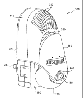
10022J As shown in FIG. 1, the evaporator 100 comprises a multi-piece housing
110 in
which a bottle 120 is detachably retained. The bottle 120 contains an
evaporable
substance (not shown), such as, for example, a liquid formulation including a
chemical
active such as an insecticide, fragrance, odor eliminator, or the like. The
term "bottle"
is used herein in its broadest possible sense, including any receptacle,
container, pouch,
etc., capable of holding a liquid formulation. A raised pattern 130 on one
side of the
bottle is engaged by an opening 140 in a front shell 150 of the evaporator
housing 110,
while a similar raised pattern 160 (shown in FIG. 6) on an opposite side of
the bottle
120 is engaged by a recess 170 (shown in FIG. 3) in a middle shell 180, in
order to
secure the bottle 120 within the evaporator 100. The front shell 150 is
sufficiently
pliant so that pulling the bottle 120 in a downward direction causes the
raised patterns
130, 160 to release from the opening 140 in the front shell 150 and the recess
170 in the
middle shell 180, respectively, thereby enabling removal of the bottle 120
from the
evaporator 100. Alternatively, the neck portion of the bottle may be designed
to snap
or screw into the evaporator housing. Suitable refill bottles are available in
a wide
CA 02481487 2004-10-06
WO 03/086487 PCT/US03/10358
-7-
variety of liquid formulations from S.C. Johnson & Son, Inc., of Racine,
Wisconsin,
under the GLADEO PLUGINSO and RAIDO brand names.
[0023] As shown in FIG. 3, the bottle 120 includes a wick 190 for drawing the
liquid
formulation out of the bottle 120 and toward an upper portion of the wick 190.
A lower
portion of the wick 190 is immersed in the liquid formulation, and the upper
portion of
the wick 190 protrudes above the neck of the bottle 120. Preferably, the wick
190 is
positioned within the bottle 120 by a cap 200 which includes a sheath 210 that
encases
the upper portion of the wick 190, except for an open area near the tip of the
wick 190.
Alternatively, a cap without a sheath can be utilized. Preferably, the wick is
about 7
mm in diameter and is constructed of ultra high molecular weight high density
polyethylene.
[0024] In the preferred embodiment illustrated in FIGS. 1-10, the evaporator
housing
110 comprises three shells - the front and middle shells 150, 180 noted above
and a
back shell 220 - which are fastened together by heat-staking or any other
suitable
fastening means, including, for example, rivets, press fit, snap fit, screws,
ultrasonic
welding, adhesives, or the like. The electrical components (discussed in more
detail
below) of the evaporator 100 are housed within the space enclosed by the
middle and
back shells 180, 220.
CA 02481487 2004-10-06
WO 03/086487 PCT/US03/10358
-8-
[00251 Referring to FIG. 2, the back she11220 contains a circular opening in
which a
known electrical plug assembly 230 is seated. The plug 230 serves the dual
purpose of
supplying power to the electrical components of the evaporator 100 and also
supporting
the evaporator 100 in a wall outlet (not shown). Preferably, the, plug
assembly 230 is
rotatable 360 degrees in,order to support the evaporator 100 in an upright
position in
both horizontal and vertical wall outlets. Advantageously, the plug assembly
230 can
be provided with an extra outlet which, as illustrated in FIG. 1, is located
on the side of
the evaporator 100 when the evaporator is plugged into a vertical wall outlet,
and on the
bottom of the evaporator 100 when the evaporator is plugged into a horizontal
wall
outlet (not shown).
[0026] As schematically illustrated in FIG. 3, the plug assembly 230 is
electrically
connected to a circuit board 240, which, in turn, is electrically connected to
a heating
device 250 and, preferably, also to a fan unit 260. The heating device 250 is
disposed
adjacent to a window 270 in the middle shell 180 which faces the tip of the
wick 190
when the bottle 120 is inserted in the evaporator 100. Heating the wick 190
enhances
the rate at which the liquid formulation evaporates into the surrounding
environment, as
described more fully below. Preferably, the heating device 250 is a 1.9 kSZ, 7
W metal
oxide resistor potted in a ceramic block. The resistor preferably has PTC
(positive
temperature coefficient) characteristics, meaning that its resistance value
increases
slightly as the resistor heats up. A suitable resistor is available from Great
Land
Enterprise Co., Ltd., of Shenzhen, China, for example. Alternatively, the
heating
CA 02481487 2004-10-06
WO 03/086487 PCT/US03/10358
-9-
device 250 can comprise one or more other types of resistor heaters, a wire-
wound
heater, a PTC heater, or the like.
[0027] The fan unit 260 is disposed within an upper portion of the housing
110. The
back shel1220 includes air inlets 280 (shown in FIG. 2) for supplying air to
the fan unit
260. As described more fully below, the fan unit 260 creates an airstream that
entrains
the evaporated liquid formulation and assists in the dispersion of the
chemical active
into the surrounding environment. Preferably, the flow rate of the fan unit
260 within
the evaporator 100 is approximately 0.5 cubic feet perminute, and the fan
speed is
approximately 2800-3800 RPM. A suitable fan unit 260 is a 12 V, DC, brushless
fan,
such as available from Power Logic Tech. Inc., of Tapei-Hsien, Taiwan.
Alternatively,
other DC or AC fans could be utilized, with appropriate adjustments to the
circuit board
240, which is described more fully below.
[0028] FIG. 11 is a schematic diagram of a preferred circuit board 240 for the
evaporator 100. Preferably, the circuit board 240 is constructed of a flame-
rated
material. The circuit board 240 includes pins 600, 610 that connect to bus
bars (not
..shown) of the plug assembly 230. The voltage applied across the pins 600,
610 is 120
V, at a frequency of 60 Hz. The heating device 250 is connected to the circuit
board
240 by a pair of rivets 620, 630. Connected in parallel are (i) a 15 V, 1.3 W
Zener
diode 640, (ii) a 22 F, 50 V aluminum electrolytic capacitor 650, rated for a
temperature of 105 C, and (iii) the fan unit 260. The circuit board 240 also
includes a
CA 02481487 2004-10-06
WO 03/086487 PCT/US03/10358
-10-
1N 4007 diode 660. The power consumption across the entire circuit is about
3.5 W to
about 4.0 W. Those skilled in the art will appreciate that numerous
alternative circuit
configurations are also possible.
[0029] Immediately downstream of the fan unit 260 is a louver structure 290,
shown in
FIG. 3, comprising at least one louver and, more preferably, a plurality of
louvers 300.
Preferably, the louver structure 290 is an integral part of the middle shell
150, but it can
also be provided separately from the middle shell 150. As illustrated in FIGS.
3 and
10, the louvers 300 are angled upwardly and away from the heating device 250
and the
upper portion of the wick 190, preferably at an angle between about 20 degrees
to about
60 degrees relative to horizontal when the evaporator 100 is in an upright
position.
[0030] The optimum louver angle varies depending on such factors as the fan
speed
and the air exchange rate within the room in which the evaporator 100 is
located. In
rooms with relatively low air exchange rates (e.g., between about 0.6 to about
1.2
exchanges per hour), a louver angle of about 40 degrees to about 45 degrees
relative to
horizontal is preferred. In rooms with higher air exchange rates, a louver
angle of
about 25 degrees to about 30 degrees relative to horizontal is preferred.
[0031] The middle shell 180 is shaped so as to direct the airstream created by
the fan
unit 260 through the louvers 300. Notably, the middle shell 180 does not
permit stray
currents of air to recirculate within the housing 110, where those currents
could have an
CA 02481487 2004-10-06
WO 03/086487 PCT/US03/10358
-11-
undesirable cooling effect on the heating device 250. A pair of openings 225
(shown in
FIG. 2) in the side of the evaporator 100 helps to achieve proper air
circulation through
the evaporator.
[0032] The front shell 150 includes a plurality of vents 310 through which the
airstream exits the evaporator 100 after passing through the louvers 300. As
the
airstream exits the evaporator 100 through the vents 310, it entrains the
evaporated
liquid formulation, which rises from the wick 190 through an opening 320 in
the front
shell 150 below the vents 310.
[0033] Tests have demonstrated that an evaporator constructed in accordance
with the
present invention disperses higher concentrations of the chemical active
within the
central "living area" of a room, as opposed to the walls, floor, or ceiling.
[0034] Those skilled in the art will appreciate that the benefits of the fan
unit 260 and
louver structure 290 described above can be achieved even in the absence of a
heating
device 250.
[0035] Optionally, the evaporator 100 also includes an adjustment mechanism
330 that
positions the upper portion of the wick 190 with respect to the heating device
250.
Preferably, the adjustment mechanism 330 includes a hollow cylindrical portion
340
that surrounds and engages part of the upper portion of the wick 190,
preferably at a
CA 02481487 2004-10-06
WO 03/086487 PCT/US03/10358
-12-
location where the wick 190 is encased by the sheath 210. The adjustment
mechanism
330 also includes a dial portion 350, accessible from outside the evaporator
housing
110, for rotating the cylindrical portion 340 about an axis of rotation. The
dial portion
350 preferably is formed integrally with the cylindrical portion 340, although
it need
not be.
[0036] Preferably, as shown in FIG. 5, a plurality of tapered lugs 360 is
provided on the
inner surface of the cylindrical portion 340. The lugs 360 are widest at their
uppermost
point, where they come in contact with the wick 190, and narrowest near the
bottom of
the cylindrical portion 340. At their uppermost point, the lugs 360 define a
circular
opening 370 that is just large enough for the wick 190 to fit through. The
center of this
opening 370 is offset relative to the axis of rotation of the cylindrical
portion 340.
[0037] Rotating the dial portion 350 of the adjustment mechanism 330 causes
the wick
190 to move toward or away from the heating device 250 in a lateral direction,
i.e., in a
direction substantially perpendicular to the longitudinal axis of the wick
190. In the
minimum intensity setting illustrated in FIGS. 4-6, the axis of the wick 190
is
positioned about 6.3 mm from the heating device 250. In this position, the
wick is
heated to a temperature of about 71-78 C. Rotating the dial portion 350
approximately
75 degrees to the right brings the wick axis to a position that is about 4.4
mm from the
heating device 250. At this maximum setting, which is illustrated in FIGS. 7-
9, the
wick is heated to a temperature of about 85-90 C, thereby resulting in a
higher
CA 02481487 2004-10-06
WO 03/086487 PCT/US03/10358
-13-
evaporation rate. The evaporator 100 also can be set to an intensity level
anywllere in
between the minimum and maximum settings. The lateral distance traveled by the
wick
190 in moving from the minimum intensity setting to the maximum intensity
setting is
preferably between about 1 mm and about 3.5 mm. In the particular preferred
embodiment described above, the lateral distance traveled by the wick 190 is
about 2
mm.
[0038] Weight loss tests have demonstrated that the evaporation rate is almost
300
percent higher at the maximum setting than at the minimum setting.
[0039] The embodiments discussed above are representative of preferred
embodiments
of the present invention and are provided for illustrative purposes only. They
are not
intended to limit the scope of the invention. Although specific structures,
dimensions,
components, etc., have been shown and described, such are not limiting.
Modifications
and variations are contemplated within the scope of the_present invention,
which is
intended to be limited only by the scope of the accompanying claims.
INDUSTRIAL APPLICABILITY
[0040] The present invention provides an electrical evaporator for use with
liquid
formulations containing a chemical active such as an insecticide, fragrance,
odor
eliminator, or the like. The evaporator inchides a fan and a louver structure
for
CA 02481487 2004-10-06
WO 03/086487 PCT/US03/10358
-14-
directing an airstream created by the fan upwardly and away from a wick, which
is
saturated with the liquid formulation. As the liquid formulation evaporates
from the
wick, it is entrained in the airstream and.dispersed into the surrounding
environment.
The fan and louver structure help to achieve a beneficial distribution of the
chemical
active within the surrounding environment, so that the chemical active is more
highly
concentrated in areas where it is most likely to be effective, and less
concentrated in
other areas. This results in more efficient use of the chemical active.