Sélection de la langue

Search

Sommaire du brevet 2481921 

Énoncé de désistement de responsabilité concernant l'information provenant de tiers

Une partie des informations de ce site Web a été fournie par des sources externes. Le gouvernement du Canada n'assume aucune responsabilité concernant la précision, l'actualité ou la fiabilité des informations fournies par les sources externes. Les utilisateurs qui désirent employer cette information devraient consulter directement la source des informations. Le contenu fourni par les sources externes n'est pas assujetti aux exigences sur les langues officielles, la protection des renseignements personnels et l'accessibilité.

Disponibilité de l'Abrégé et des Revendications

L'apparition de différences dans le texte et l'image des Revendications et de l'Abrégé dépend du moment auquel le document est publié. Les textes des Revendications et de l'Abrégé sont affichés :

  • lorsque la demande peut être examinée par le public;
  • lorsque le brevet est émis (délivrance).
(12) Brevet: (11) CA 2481921
(54) Titre français: ANTENNE EMF GRANDE PORTEE
(54) Titre anglais: EXTENDED RANGE EMF ANTENNA
Statut: Réputé périmé
Données bibliographiques
(51) Classification internationale des brevets (CIB):
  • E21B 47/026 (2006.01)
  • E21B 19/00 (2006.01)
  • E21B 43/00 (2006.01)
  • G01V 3/00 (2006.01)
  • H01J 15/00 (2006.01)
  • H01Q 1/04 (2006.01)
  • H01Q 1/36 (2006.01)
  • H01Q 11/00 (2006.01)
  • E21B 47/12 (2006.01)
(72) Inventeurs :
  • RADZINSKI, PAUL E. (Etats-Unis d'Amérique)
(73) Titulaires :
  • WEATHERFORD TECHNOLOGY HOLDINGS, LLC (Etats-Unis d'Amérique)
(71) Demandeurs :
  • COMPUTALOG USA, INC. (Etats-Unis d'Amérique)
(74) Agent: PARLEE MCLAWS LLP
(74) Co-agent:
(45) Délivré: 2011-02-01
(86) Date de dépôt PCT: 2003-04-16
(87) Mise à la disponibilité du public: 2003-10-30
Requête d'examen: 2008-03-31
Licence disponible: S.O.
(25) Langue des documents déposés: Anglais

Traité de coopération en matière de brevets (PCT): Oui
(86) Numéro de la demande PCT: PCT/US2003/011657
(87) Numéro de publication internationale PCT: WO2003/090311
(85) Entrée nationale: 2004-10-07

(30) Données de priorité de la demande:
Numéro de la demande Pays / territoire Date
60/372,863 Etats-Unis d'Amérique 2002-04-16

Abrégés

Abrégé français

Un système servant à effectuer des mesures pendant un forage comporte généralement des conduites métalliques qui s'étendent dans le sol et sont reliées à une antenne. Les conduites métalliques et l'antenne sont reliées à un type d'équipement de fond de trou. L'antenne émet ou reçoit des signaux respectivement à destination/en provenance d'un émetteur récepteur situé à la surface, cet émetteur récepteur étant relié aux conduites métalliques et à la terre. Ce système est amélioré par le fait qu'une pluralité de segments de tige de forage câblée sont assemblées pour former un segment dans lequel l'antenne ne forme qu'une seule pièce avec les conduites métalliques. Une extrémité du segment de tige de forage câblée est connectée à l'équipement de fond de trou et l'autre extrémité est connectée à des conduites métalliques classiques.


Abrégé anglais


A measuring while drilling system (28) typically has a metal pipework (16)
extending underground connected to an antenna (26a). The metal pipework (16)
and the antenna (26a) are both connected to a type of downhole equipment. The
antenna (26a) transmits or receives signals to/from a transceiver (18) located
on the surface, and the transceiver (18) is connected to the metal pipeword
(16) and to a ground (24). The system is improved by joining a plurality of
sections of wired drill pipe (40) together to form a section where the antenna
(26a) is integral with the metal pipework (16). One end of the section of
wired drill pipe (40) is joined to downhole equipment and another end is
joined to a conventional metal pipework (16).

Revendications

Note : Les revendications sont présentées dans la langue officielle dans laquelle elles ont été soumises.


I claim:
1. A measuring while drilling apparatus having a metal pipework extending
underground and
connected to an antenna, wherein both the metal pipework and the antenna are
connected to a
type of downhole equipment, whereby the antenna transmits/receives signals
with a transceiver
located on a surface, wherein the transceiver is connected to the metal
pipework and to a ground,
comprising:
a plurality of sections of wired drill pipe joined together to form the
antenna and a section
where the antenna is integral with the metal pipework
2. The apparatus according to claim 1 wherein the length of said plurality of
sections of wired
drill pipe is less than the length of the metal pipework.
3. The apparatus according to claim 2, wherein the length of said plurality of
sections of wired
drill pipe joined together is a constant ranging from 2,000 to 9,000 feet.
4. The apparatus according to claim 2, wherein the length of said plurality of
sections of wired
drill pipe joined together is a constant ranging from 2,000 to 5,000 feet.
5. The apparatus according to claim 1 wherein said plurality of sections of
wired drill pipe
include a drill pipe casing with a wall; and a wire embedded into the wall of
the drill pipe casing.
6. A new use for a section of wired drill pipe, comprising:
installing one end of the section of wired drill pipe on a type of downhole
equipment;
installing a conventional metal pipework to the other end of the section of
wired drill
pipe; and
using the section of wired drill pipe as an antenna for a well operation
located below a
surface from which the metal pipework emanates.


7. The method according to claim 6 wherein the section of wired drill pipe is
a first section of
wired drill pipe, further including the step of attaching a second section of
wired drill pipe to the
first section of wired drill pipe for connection between the downhole
equipment and the
conventional metal pipework.
8. The method according to claim 7, further including joining additional
sections of wired drill
pipe for forming an antenna having a length ranging from 2,000 to 5,000 feet.
9. The method according to claim 7, further including joining additional
sections of wired drill
pipe for forming an antenna having a length ranging from 2,000 to 9,000 feet.
10. In an apparatus for telemetering information between a type of downhole
equipment at a
bottom of an operation and a surface, the apparatus having the combination of
a metal pipework;
a transceiver at the surface connected to both a ground, spaced from the
operation, and the metal
pipework; and an antenna for applying signals between two points, wherein the
antenna has the
improvement comprising:
a plurality of sections of wired drill pipe joined together to form the
antenna, wherein one
end of said plurality of sections of wired drill pipe is connected to the
metal pipework and
another end is connected to the downhole equipment.
11. The apparatus according to claim 10 wherein said plurality of sections of
wired drill pipe
have a length which is less than the length of the metal pipework.
12. The apparatus according to claim 11, wherein the length of said plurality
of sections of
wired drill pipe joined together is a constant ranging from 2,000 to 9,000
feet.
13. The apparatus according to claim 11, wherein the length of said plurality
of sections of
wired drill pipe joined together is a constant ranging from 2,000 to 5,000
feet.
14. The apparatus according to claim 10 wherein said plurality of sections of
wired drill pipe
include a drill pipe casing with a wall; and a wire embedded into the wall of
the drill pipe casing.
6


15. In a method for telemetering information between a type of downhole
equipment at a bottom
of an operation and a surface, the method having the combination of providing
an antenna
proximate the downhole equipment at the bottom of the operation and a
transceiver at the surface
connected to both a ground, spaced from the operation, and to a metal pipework
of the operation;
and applying signals with the antenna between two points along the metal
pipework, wherein the
step of providing the antenna has the improvement comprising:
joining a plurality of sections of wired drill pipe together to form the
antenna; and
connecting the plurality of sections of wired drill pipe between the metal
pipework of the
operation and the downhole equipment.
16. The method according to claim 15, wherein said step of joining the
plurality of sections of
wired drill pipe together to form the antenna includes joining the plurality
of sections of wired
drill pipe to a length ranging from 2,000 to 5,000 feet.
17. The method according to claim 15, wherein said step of joining the
plurality of sections of
wired drill pipe together to form the antenna includes joining the plurality
of sections of wired
drill pipe to a length ranging from 2,000 to 9,000 feet.
7

Description

Note : Les descriptions sont présentées dans la langue officielle dans laquelle elles ont été soumises.


CA 02481921 2004-10-07
WO 03/090311 PCT/US03/11657
TITLE: EXTENDED RANGE EMF ANTENNA
SPECIFICATION
CROSS-REFERENCE TO RELATED APPLICATIONS
[0001] This application claims the benefit of US provisional application
number
60/372,863 filed April 16, 2002.
STATEMENTS REGARDING FEDERALLY SPONSOR RESEARCH OR
DEVELOPMENT
[0002] Not applicable.
REFERENCE TO A MICROFICHE APPENDIX
[0003] Not applicable.
BACKGROUND OF THE INVENTION
Description of the Related Art
[0004] The present application hereby incorporates by reference the teachings
and
disclosures of US patent number 5,394,141 issued Feb. 28, 1995 and of US
patent number
6,223,826 issued May 1, 2001.
[0005] For purposes of this application, the following definition is intended
to apply.
The term "wired drill pipe" shall mean drill pipe sections having wire
preinstalled and
secured within the interior of the drill pipe section in a manner where a
conductive path is
formed through a like drill pipe section having preinstalled wire when the
like drill pipe
section is adjoined to the end of the preceding drill pipe section. A variety
of embodiments
thereof are described in US patent number 6,223,826 issued May 1, 2001, where
such a


CA 02481921 2004-10-07
WO 03/090311 PCT/US03/11657
device is generally referred to as the arrangement for providing an
electrically conductive
path installed in drill pipe sections having a threaded male end and a
threaded female end.
BRIEF SUMMARY OF THE INVENTION
[0006] The present invention uses wired drill pipe to form a long dipole
transmitting
antenna such as the transmitter described in US patent number 5,394,141 issued
Feb. 28,
1995, and uses such wired drill pipe for extended range (boosting) emf
signaling in place of
the wireline currently used for extended range signaling. The transmitter
described in patent
number 5,394,141 is a running wire or wireline which dangles, for example, for
3,000 feet
within the drill pipe and which is attached at both ends of such wire to the
drill pipe.
[0007] Several advantages may be achieved by replacing such a wireline with
the
wired drill pipe. For example, the need for having pulleys and other devices
at the surface for
running wire into the drill pipe may be eliminated; the cost and complexity of
installing the
wireline within the drill pipe at the well site may be eliminated; downhole
problems may be
reduced like, for example, the risk for occurrences of wire breakage due to
circumstances
such as corrosion may be reduced; the time required to deploy the wireline
within the drill
pipe and to retract it from the drill pipe may be reduced or eliminated which
may result in an
overall reduction of the rig time required to perform a project; the overall
system may be
safer due to less complexity; and the wired drill pipe may be more reliable
than the wireline.
[0008] One type of a measuring while drilling system typically has a metal
pipework
extending underground connected to an antenna. The metal pipework and the
antenna are
both connected to downhole equipment. The antenna transmits or receives
signals to/from a
transceiver located on the surface, and the transceiver is connected to the
metal pipework and
to a ground. The system is improved by joining a plurality of sections of
wired drill pipe
together to form a section where the antenna is integral with the metal
pipework. One end of
the section of wired drill pipe is joined to downhole equipment and another
end is joined to a
conventional metal pipework.
BRIEF DESCRIPTION OF THE SEVERAL VIEWS OF THE DRAWINGS
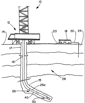
[0009] Fig. 1 is a schematic elevational view of a measuring while drilling
operation.
Fig. 2 is a sectional view of a male end of a piece of wired drill pipe nearly
connected to a female end of a like piece of wired drill pipe.
2


CA 02481921 2004-10-07
WO 03/090311 PCT/US03/11657
DETAILED DESCRIPTION OF THE INVENTION
[0010] Figure 1 shows a schematic of a typical measuring while drilling
operation 10
having a rig 12 on the surface 14 for drilling an open hole 15. Conventional
metal pipework
or drill pipe 16 and a length of casing 17 emanates from the rig 12. A
transceiver 18 is also
located at the surface and is connected by a line 20 to the casing 17 (or by
some means to any
pipe in the well) and by a line 22 to the ground 24 (which may be the surface
14 or at a
position below the ocean). The transceiver 18 can send or receive signals from
a
transmitter/receiver device 26 which transmits/receives emf signals which
emanate through
the earth 28 for transmission/reception of directional data, gamma ray data,
resistivity data,
annular pressure data, etc. Additional details of such a system are described
in US patent
number 5,394,141.
[0011] In the present telemetry embodiment(s), for purposes of the
transmitter/receiver device 26, one or more sections of wired drill pipe 40
are connected at
cane end to some type of downhole equipment 30 as the downhole equipment 30 is
lowered
below the surface 14. The other end of the wired drill pipe 40 is joined to
the metal pipework
16. The sections of wired drill pipe 40 form an antenna 26a (which may be a
transmitter
and/or receiver) and a section of drill pipe bridging the conventional metal
pipework 16 to the
downhole equipment 30.
[0012] Figure 2 shows one embodiment of the male end 42 with threading 44 and
the
female end 46 with threading 48 of respective wired drill pipe sections 40a
and 40b. Several
other embodiments are described in US patent number 6,223,826. The wired drill
pipe 40 is
constructed with mounting devices 50a and 50b for mounting and securing wires)
52a,b
respectively within or inside the drill pipe casings 54a and 54b. In the
embodiment shown,
the respective ends 56a and 56b of the wires 52a and 52b are curled like a
halo such that
wires 52a and 52b meet to form a conductive path when the male end 42 is
joined to the
female end 46. Other details/embodiments of wired drill pipe 40 are described
in US patent
number 6,223,826. Further embodiments of wired drill pipe which could be
incorporated into
various embodiments of the invention include wires) 52 built or embedded into
the wall 53
of the drill pipe casings 54a and 54b such that the pipe wall 53 and the wire
52 are unitary,
such as, for example, wires) 52 inserted into a groove formed in the wall 53
of the drill pipe
(preferably on the inside of the wall 53). In another embodiment wires) 52 may
lay
alongside (or dangle freely) in the bore of the drill pipe casings 54a and
54b.
3


CA 02481921 2004-10-07
WO 03/090311 PCT/US03/11657
[0013] The wires 52 are preferably insulated to create an electrically
isolated
conductive path and may, for example, have a 3/l6th inch diameter or a
diameter as needed to
function as the antenna 26a.
[0014) The wired drill pipe sections 40 may be joined together to form an
integral
pipeworlc casing and antenna 26a of any desirable length. Normally, the wired
drill pipe
sections 40 will be joined together to form an antenna 26a ranging from 2,000
to 5,000 feet in
length for extended range signaling. However, for downhole depths of 18,000
feet, the wired
drill pipe sections 40 could be joined to form an antenna 26a which is, fox
example, 9,000
feet long. It is to be understood that the antenna 26a could be longer than
9,000 feet or
shorter than 2,000 feet if necessary or desired. Preferably, the lower end of
the antenna 26a is
communicatively connected to the downhole equipment 30 instruments/sensors and
the upper
end of the antenna 26a is electronically connected to the pipe 16, although
other known
connections may be implemented.
[0015] In conclusion, therefore, it is seen that the present invention and the
embodiments disclosed herein are well adapted to carry out the objectives and
obtain the ends
set forth. Certain changes can be made in the subject matter without departing
from the spirit
and the scope of this invention. It is realized that changes are possible
within the scope of
this invention and it is further intended that each element or step recited is
to be understood
as referring to all equivalent elements or steps. The description is intended
to cover the
invention as broadly as legally possible in whatever form it may be utilized.
4

Dessin représentatif
Une figure unique qui représente un dessin illustrant l'invention.
États administratifs

Pour une meilleure compréhension de l'état de la demande ou brevet qui figure sur cette page, la rubrique Mise en garde , et les descriptions de Brevet , États administratifs , Taxes périodiques et Historique des paiements devraient être consultées.

États administratifs

Titre Date
Date de délivrance prévu 2011-02-01
(86) Date de dépôt PCT 2003-04-16
(87) Date de publication PCT 2003-10-30
(85) Entrée nationale 2004-10-07
Requête d'examen 2008-03-31
(45) Délivré 2011-02-01
Réputé périmé 2020-08-31

Historique d'abandonnement

Il n'y a pas d'historique d'abandonnement

Historique des paiements

Type de taxes Anniversaire Échéance Montant payé Date payée
Le dépôt d'une demande de brevet 400,00 $ 2004-10-07
Enregistrement de documents 100,00 $ 2004-12-23
Taxe de maintien en état - Demande - nouvelle loi 2 2005-04-18 100,00 $ 2005-03-22
Enregistrement de documents 100,00 $ 2005-03-24
Enregistrement de documents 100,00 $ 2005-06-28
Taxe de maintien en état - Demande - nouvelle loi 3 2006-04-17 100,00 $ 2006-03-15
Enregistrement de documents 100,00 $ 2006-05-03
Taxe de maintien en état - Demande - nouvelle loi 4 2007-04-16 100,00 $ 2007-03-08
Taxe de maintien en état - Demande - nouvelle loi 5 2008-04-16 200,00 $ 2008-03-13
Requête d'examen 800,00 $ 2008-03-31
Taxe de maintien en état - Demande - nouvelle loi 6 2009-04-16 200,00 $ 2009-03-18
Taxe de maintien en état - Demande - nouvelle loi 7 2010-04-16 200,00 $ 2010-03-11
Taxe finale 300,00 $ 2010-11-22
Taxe de maintien en état - brevet - nouvelle loi 8 2011-04-18 200,00 $ 2011-03-10
Taxe de maintien en état - brevet - nouvelle loi 9 2012-04-16 200,00 $ 2012-03-14
Taxe de maintien en état - brevet - nouvelle loi 10 2013-04-16 250,00 $ 2013-03-14
Taxe de maintien en état - brevet - nouvelle loi 11 2014-04-16 250,00 $ 2014-03-12
Taxe de maintien en état - brevet - nouvelle loi 12 2015-04-16 250,00 $ 2015-04-09
Taxe de maintien en état - brevet - nouvelle loi 13 2016-04-18 250,00 $ 2016-03-23
Taxe de maintien en état - brevet - nouvelle loi 14 2017-04-18 250,00 $ 2017-03-22
Enregistrement de documents 100,00 $ 2017-05-26
Taxe de maintien en état - brevet - nouvelle loi 15 2018-04-16 450,00 $ 2018-03-21
Titulaires au dossier

Les titulaires actuels et antérieures au dossier sont affichés en ordre alphabétique.

Titulaires actuels au dossier
WEATHERFORD TECHNOLOGY HOLDINGS, LLC
Titulaires antérieures au dossier
COMPUTALOG USA, INC.
PRECISION DRILLING TECHNICAL SERVICES GROUP INC.
PRECISION ENERGY SERVICES LTD.
PRECISION ENERGY SERVICES ULC
RADZINSKI, PAUL E.
WEATHERFORD CANADA PARTNERSHIP
Les propriétaires antérieurs qui ne figurent pas dans la liste des « Propriétaires au dossier » apparaîtront dans d'autres documents au dossier.
Documents

Pour visionner les fichiers sélectionnés, entrer le code reCAPTCHA :


Pour visualiser une image, cliquer sur un lien dans la colonne description du document. Pour télécharger l'image (les images), cliquer l'une ou plusieurs cases à cocher dans la première colonne et ensuite cliquer sur le bouton "Télécharger sélection en format PDF (archive Zip)" ou le bouton "Télécharger sélection (en un fichier PDF fusionné)".

Liste des documents de brevet publiés et non publiés sur la BDBC .

Si vous avez des difficultés à accéder au contenu, veuillez communiquer avec le Centre de services à la clientèle au 1-866-997-1936, ou envoyer un courriel au Centre de service à la clientèle de l'OPIC.


Description du
Document 
Date
(yyyy-mm-dd) 
Nombre de pages   Taille de l'image (Ko) 
Abrégé 2004-10-07 2 70
Revendications 2004-10-07 3 127
Dessins 2004-10-07 2 34
Description 2004-10-07 4 194
Dessins représentatifs 2004-10-07 1 16
Page couverture 2004-12-16 1 41
Description 2010-05-03 4 190
Revendications 2010-05-03 3 99
Dessins représentatifs 2011-01-11 1 10
Page couverture 2011-01-11 2 47
Correspondance 2005-02-14 1 24
Taxes 2007-03-08 1 37
PCT 2004-10-07 8 278
Cession 2004-10-07 3 119
Correspondance 2004-12-14 1 26
Cession 2004-12-23 2 97
Cession 2005-03-24 4 169
Taxes 2005-03-22 1 33
Correspondance 2005-05-16 1 23
Cession 2005-06-28 4 162
Cession 2005-06-23 2 85
Taxes 2006-03-15 1 36
Cession 2006-05-03 13 391
Cession 2006-05-03 9 364
Taxes 2010-03-11 1 200
Poursuite-Amendment 2008-03-31 1 40
Taxes 2008-03-13 1 48
Taxes 2009-03-18 1 40
Poursuite-Amendment 2009-11-03 3 86
Poursuite-Amendment 2010-05-03 8 331
Correspondance 2010-11-22 1 34
Taxes 2011-03-10 1 202