Note : Les descriptions sont présentées dans la langue officielle dans laquelle elles ont été soumises.
CA 02482518 2011-04-07
WO 03/093782 PCT/US03112463
-1-CORROSIVE LIQUID DETECTION SENSOR CABLE AND METHOD
FIELD OF THE INVENTION
This invention relates to cables for sensing the presence of a corrosive
liquid.
BACKGROUND OF THE INVENTION
Transporting liquids such as crude oil, refined petroleum products, or
corrosive
liquids such as concentrated acids or bases is often accomplished utilizing
tanks and
underground pipelines. Underground pipelines are subject to leakage from the
piping,
fittings, and valves. When an underground pipe carrying a hazardous or
corrosive liquid
develops a leak, the leak must first be detected and located before it can be
repaired.
Various systems for detecting leaks are well-known. For example, sensor cables
may be used to detect changes in variables along an elongate path, such as the
presence of
a liquid such as water, an organic solvent, or a corrosive liquid. Sensor
cables may be
extended in a pipeline, along the length or longitudinal axis or at various
sections or
points at which the leakage of liquids tends to occur.
Known sensor cables generally comprise first and second conductors spaced
apart
from one another. If an electrically conductive liquid contacts both the first
and second
conductors, an electrical connection is made. If there is not enough liquid
present to
create contact between the first and second conductors there will be no
connection.
Conventional sensor cables will detect any conductive liquid, including
rainwater and
groundwater. Therefore, these sensor cables are subject to false alarms since
such
conventional sensor cables are not capable of differentiating between common
conductive
liquids such as ground water or rainwater containing mild concentrations of
corrosive
components and conductive, highly corrosive, liquids such as concentrated
sulfuric acid,
hydrochloric acid, nitric acid, acetic acid, strong mineral acids, or strong
bases such as
sodium hydroxide.
It is an object of this invention to provide a cable particularly suitable for
detecting the location of a leak.
It is a further object of this invention to provide a method of detecting and
locating the presence of a leak utilizing the cable of the present invention.
SUMMARY OF THE INVENTION
The present invention relates to a cable particularly suitable for detecting
corrosive liquids and for detecting and locating leaks and a method of using
the cable. In
more detail the cable of the current invention comprises first and second
sensing wires
CA 02482518 2004-10-13
WO 03/093782 PCT/US03/12463
-2-
and a core member around which the first and second sensing wires are wrapped.
Further,
each sensing wire comprises a center conductor and at least one conductive
layer. At least
one of the sensing wires further comprises at least one non-conductive surface
layer. The
cable may further comprise insulating wires to assist in determining the exact
location of
the leak.
An alternate embodiment of the cable comprises first and second sensing wires
and a core member around which the first and second sensing wires are wrapped.
The
first and second sensing wires and the core member are encapsulated by at
least one non-
conductive surface layer. The cable may further comprise insulating wires to
assist in
determining the exact location of the leak.
The cables of the present invention may be useful as part of an electrical
circuit to
detect the location of leaks. The present invention also relates to a method
of using the
cables to detect and locate the presence of a leak.
BRIEF DESCRIPTION OF THE DRAWINGS
Figure 1 is a plan view of a cable of the current invention.
Figure 2 is a cross-sectional view of a cable of the current invention along
line 2-2 of
Figure 1.
Figure 3 is a cross-sectional view of an alternate embodiment cable of the
current
invention along line 2-2 of Figure 1.
DETAILED DESCRIPTION OF THE INVENTION
The present invention relates to a cable particularly suitable for detecting
corrosive liquids and for detecting and locating leaks and a method of using
the cable. In
more detail the cable of the current invention comprises first and second
sensing wires
and a core member around which the first and second sensing wires are wrapped.
Further,
each sensing wire comprises a center conductor and at least one conductive
layer. At least
one of the sensing wires further comprises at least one non-conductive surface
layer. The
cable may further comprise insulating wires to assist in determining the exact
location of
the leak.
An alternate embodiment of the cable comprises first and second sensing wires
and a core member around which the first and second sensing wires are wrapped.
The
first and second sensing wires and the core member are encapsulated by at
least one non-
conductive surface layer. The cable may further comprise insulating wires to
assist in
determining the exact location of the leak.
CA 02482518 2004-10-13
WO 03/093782 PCT/US03/12463
-3-
The cables of the present invention may be useful as part of an electrical
circuit to
detect the location of leaks. The present invention also relates to a method
of using the
cables to detect and locate the presence of a leak.
In more detail the cable comprises first and second sensing wires and a core
member around which the first and second sensing wires are wrapped. Each of
the first
and second sensing wires of the cable comprise a center conductor and at least
one
conductive layer. The center conductor of each sensing wire is comprised of
any metal,
such as a solid or stranded metal wire or metal braid made from copper,
nickel, tin-plated
copper, metal alloys comprised of nickel and copper, or other suitable
material. The at
least one conductive layer of the sensing wire surrounds the center conductor
and is in
contact with the center conductor. Preferably, each sensing wire comprises one
conductive layer. The conductive layer not only acts as an electrical
conductor but also as
a protective layer to prevent corrosion to the center conductor of the sensing
wire upon
exposure to liquids. The conductive layer is formed from a conductive
composition which
comprises a polymeric matrix in which is dispersed a particulate conductive
filler. Any
conductive polymer composition may be used. For many applications it is
preferred that
the polymer be selected for its solvent and chemical resistance to materials
with which it
may come in contact. A useful polymer is polyvinylidene fluoride. Any suitable
conductive filler may be used, for example carbon black, graphite, metal,
metal oxide,
particles of conductive polymer, or a mixture thereof. In addition, the
conductive polymer
composition may contain inert fillers, crosslinking agents, plasticizers,
lubricants, or other
process aids. The appropriate resistivity level of the composition will vary
depending on
the application, but is preferably in the range of 0.1 to 50,000 ohm-cm, more
particularly
1 to 1,000 ohm-cm, most preferably 1 to 250 ohm-cm.
At least one of the first and second sensing wires further comprises at least
one
non-conductive surface layer. Preferably, both the first and second sensing
wires have at
least one non-conductive surface layer. More preferably, each of the first and
second
sensing wires comprise only one non-conductive layer. The at least one non-
conductive
surface layer surrounds the at least one conductive layer and is in contact
with the
conductive layer. The non-conductive surface layer is any material, preferably
polymeric,
that is dissolved or solubilized in corrosive liquids contained in the
pipeline. The non-
conductive surface layer is not dissolved or solubilized in conductive liquids
such as
rainwater or groundwater. The selection of non-conductive surface layers is
dependent on
the application and type of leak to be detected. For example, it is known that
many
commercially available grades of polyurethanes dissolve upon contact with
concentrated
CA 02482518 2004-10-13
WO 03/093782 PCT/US03/12463
-4-
sulfuric acid. Preferably, the at least one non-conductive surface layer is
selected from
commercially available polyamides and polyurethanes. Exemplary polyurethanes
include
Type 4-20630 and Type 4-20538, produced and sold by Dymax Corporation,
Torrington,
CT.
The core member of the cable has an outer surface comprising a deformable
insulating material. The deformable material may be a thermoplastic, for
example
polyvinylidene fluoride, or an elastomer, for example thermoplastic elastomer
(TPR), or a
blend of materials depending on the physical and thermal properties desired
for the
application. For many applications it is desirable that the core member also
comprise a
central support member that is surrounded by the deformable material. The
central
support member provides physical reinforcement of the core member. The central
support
member comprises a center conductor and at least one insulating polymeric
layer. The
center conductor is comprised of any metal, such as a solid or stranded metal
wire or
metal braid made from copper, nickel, tin-plated copper, metal alloys, or
other suitable
material. If the central support member is conductive, as in the case of a
wire, the central
support member can be used as part of an electrical circuit to detect faults
or breaks in
one of the sensing wires or any other components.
The first and second sensing wires may be the same or different in
composition,
construction, and size. Depending on the application, the size of the center
conductor of
the sensing wire and the thickness of the conductive and non-conductive
polymer layers
of the sensing wires may vary. In order to have adequate flexibility, it is
preferred that the
outer diameter of the first and the second sensing wires be 0.005 to 0.500
inch (0.0127 to
1.27 cm), preferably 0.020 to 0.200 inch (0.051 to 0.508 cm), more preferably
0.025 to
0.100 inch (0.064 to 0.254 cm), most preferably 0.025 to 0.060 inch (0.064 to
0.152 cm).
In an alternate embodiment of the invention the cable comprises first and
second
sensing wires and a core member around which the first and second sensing
wires are
wrapped and the wires and core member are encapsulated by at least one non-
conductive
layer. Each of the first and second sensing wires of the cable comprises a
center
conductor and at least one conductive layer. The center conductor of each
sensing wire is
comprised of any metal, such as a solid or stranded metal wire or metal braid
made from
copper, nickel, tin-plated copper, metal alloys, or other suitable material.
The at least one
conductive layer of the sensing wire surrounds the center conductor and is in
contact with
the center conductor. Preferably, each sensing wire comprises one conductive
layer. This
conductive layer not only acts as an electrical conductor but also as a
protective layer to
prevent corrosion to the center conductor of the sensing wire upon exposure to
liquids.
CA 02482518 2004-10-13
WO 03/093782 PCT/US03/12463
-5-
For purposes of this invention a conductive layer is formed from a conductive
composition which comprises a polymeric matrix in which is dispersed a
particulate
conductive filler. Any conductive polymer composition may be used. For many
applications it is preferred that the polymer be selected for its solvent and
chemical
resistance to materials with which it may come in contact. A useful polymer is
polyvinylidene fluoride. Any suitable conductive filler may be used, for
example carbon
black, graphite, metal, metal oxide, particles of conductive polymer, or a
mixture thereof.
In addition, the conductive polymer composition may contain inert fillers,
crosslinking
agents, plasticizers, lubricants, or other process aids. The appropriate
resistivity level of
the composition will vary depending on the application, but is preferably in
the range of
0.1 to 50,000 ohm-cm, more preferably 1 to 1,000 ohm-cm, most preferably 1 to
250
ohm-cm.
The first and second sensing wires together with the core member are
encapsulated by at least one non-conductive surface layer. The non-conductive
surface
layer is any material, preferably polymeric, that is dissolved or solubilized
in corrosive
liquids contained in the pipeline. The non-conductive surface layer is not
dissolved or
solubilized by conductive liquids such as rainwater or groundwater. The
selection of non-
conductive surface layers is dependent on the application and type of leak to
be detected.
For example, it is known that many commercially available grades of
polyurethanes
dissolve upon contact with concentrated sulfuric acid. Preferably, the at
least one non-
conductive surface layer is selected from commercially available polyamides
and
polyurethanes. Exemplary polyurethanes include Type 4-20630 and Type 4-20538,
produced and sold by Dymax Corporation, Torrington, CT.
The core member of the cable has an outer surface comprising a deformable
insulating material. The deformable material may be a thermoplastic, for
example
polyvinylidene fluoride, or an elastomer, for example thermoplastic elastomer
(TPR), or a
blend of materials depending on the physical and thermal properties desired
for the
application. For many applications it is desirable that the core member also
comprise a
central support member that is surrounded by the deformable material. This
central
support member provides physical reinforcement of the core member. The central
support
member comprises a center conductor and at least one insulating polymeric
layer. The
center conductor is comprised of any metal, such as a solid or stranded metal
wire or
metal braid made from copper, nickel, tin-plated copper, metal alloys, or
other suitable
material. If the central support member is conductive, as in the case of a
wire, the central
support member can be used as part of an electrical circuit to detect faults
or breaks in
CA 02482518 2004-10-13
WO 03/093782 PCT/US03/12463
-6-
one of the sensing wires or any other components.
The first and second sensing wires may be the same or different in
composition,
construction, and size. Depending on the application, the size of the metal
center
conductor of the sensing wire and the thickness of the conductive and non-
conductive
polymer layers of the sensing wires may vary. In order to have adequate
flexibility, it is
preferred that the outer diameter of the first and the second sensing wires be
0.005 to
0.500 inch (0.0127 to 1.27 cm), preferably 0.020 to 0.200 inch (0.051 to 0.508
cm), more
preferably 0.025 to 0.100 inch (0.064 to 0.254 cm), most preferably 0.025 to
0.060 inch
(0.064 to 0.152 cm).
The cables of the described embodiments can be produced in the following
manner. The first sensing wire is positioned in a first channel of the core
member. The
first channel, which may be of any suitable shape, partially surrounds the
first sensing
wire and allows exposure of the first sensing wire to a liquid. At least one,
and preferably
two, first shoulders extend outwardly beyond the first sensing wire to an
extent that the
first sensing wire will not protrude from the channel. The extent to which the
shoulder
protrudes beyond the first sensing wire is preferably from 0.002 to 0.020 inch
(0.005 to
0.051 cm).
The second sensing wire is positioned in a second channel in the core member
of
the cable in the same manner as that of the first sensing wire. At least one,
and preferably
two, shoulders extend outwardly beyond the second sensing wire to protect the
second
sensing wire. The dimensions of the second sensing wire and the second chaimel
may be
the same or different from those of the first sensing wire and first channel.
The first and second sensing wires are applied in a generally spiral path
along the
length of the cable and are wrapped around the core member. In this
specification, the
term "spiral" means any form of progression of the sensing wire down the
length of the
cable, whether the pitch is constant or varies, and whether the progression is
regular or
irregular. If the outer surface of the core member is heated to a temperature
sufficient to
deform the deformable material, when the first and second sensing wires are
wrapped
around the core member, they become embedded into the deformable material and
form
first and second channels. This technique, in which the conductor "carves" the
channel,
allows the conductors to be positioned securely within each channel and
prevents them
from sliding out. In a preferred construction, the positions of the first and
second sensing
wires are balanced, that is the cable can be bent equally easily in any
direction. For many
embodiments, the first and second sensing wires are equidistant from the
central axis of
the conductor. Thus if the core member has a generally circular shape, the
first sensing
CA 02482518 2004-10-13
WO 03/093782 PCT/US03/12463
-7-
wire and the second sensing wire are on opposite sides of the core member
diameter
rather than adjacent to one another.
For some applications, it is useful to determine the exact location of the
leak. For
this purpose one can utilize one or more insulating wires in combination with
the cable
comprising first and second sensing wires and a core member. By the use of the
proper
electronic components connected to the first and second sensing wires and to
one or more
insulating wires, the exact location of the electrical connection produced at
the site of the
leak can be determined. The insulating wires comprise a central wire which is
surrounded
by an insulating material such as a polymer. A first, as well as a second,
insulating wire
1o can be wrapped around the core member of the cable separately or at the
same time as the
one or both of the first and second sensing wires are wrapped around the core
member.
Alternatively, if the central support member is an insulated wire, it can be
used in place of
one of the first and second insulating wires. It is preferred that the first
and second
insulating wires are balanced, that is they form part of a symmetrical cable,
equally
spaced from one another and from each of the first and second sensing wires. A
preferred
embodiment is a four wire system in which a first insulating wire acts as a
return wire to a
voltage meter and a second insulating wire acts as an auxiliary wire. Suitable
electronics
and methods of detecting the location of a leak are well-known.
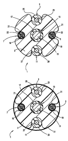
The invention is illustrated by the drawing in which Figure 1 shows a plan
view of
a cable 1. A core member 3 is wrapped in a spiral pattern with a first sensing
wire 5, a
first insulating wire 9, a second sensing wire 7, and a second insulating wire
11.
Figure 2 is a cross-sectional view of the cable 1 along line 2-2 of Figure 1.
In this
embodiment, polyvinylidene fluoride comprises the core member 3 and surrounds
a
central support member 13 which comprises a stranded nickel-plated copper wire
center
conductor 15 and an insulating ethylene/tetrafluoroethylene copolymer layer
17. The first
sensing wire 5 and second sensing wire 7 are embedded into the core member 3.
Each
sensing wire 5,7 comprises a center conductor 19 of solid Alloy 294 wire
(produced and
sold by American Wire Corporation, Sandy Hook, CT) surrounded by a carbon-
filled
polyvinylidene fluoride layer 21, which is surrounded by a layer of non-
conductive
polyurethane 22. The first insulating wire 9 comprises a solid tin-plated
copper center
wire 23 surrounded by an insulating layer of polyvinylidene fluoride 25 and
the second
insulating wire 11 comprises a solid tin-plated copper center wire 27
surrounded by an
insulating polymer layer of polyvinylidene fluoride 29.
Figure 3 is a cross-sectional view of a cable 1 according to an alternate
embodiment. In this embodiment, polyvinylidene fluoride comprises the core
member 3
CA 02482518 2004-10-13
WO 03/093782 PCT/US03/12463
-B-
and surrounds a central support member 13 which comprises a stranded nickel-
plated
copper wire center conductor 15 and an insulating polymeric layer 17 made from
ethylene/tetrafluoroethylene copolymer. The first sensing wire 5 and second
sensing wire
7 are embedded into the core member 3. Each sensing wire 5,7 comprises a
center
conductor 19 made from solid Alloy 294 wire, surrounded by a carbon-filled
polyvinylidene fluoride layer 21. The first insulating wire 9 comprises a
solid tin-plated
copper center wire 23 surrounded by an insulating layer of polyvinylidene
fluoride 25 and
the second insulating wire 11 comprises a center wire 27 surrounded by an
insulating
layer of polyvinylidene fluoride 29. A non-conductive layer of polyurethane 31
surrounds
core member 3, first sensing wire 5, second sensing wire 7, first insulating
wire 9, and
second insulating wire 11.
The cables of the described invention may be used to determine the presence
and
location of a leak in the following manner. A cable made according to the
described
invention is extended along the length of a pipeline carrying a corrosive
liquid. Whenever
corrosive liquid contained within the pipeline leaks, the corrosive liquid
contacts the
cable and a non-conductive surface layer of the cable, upon contact with the
corrosive
liquid, is dissolved or solubilized, exposing an underlying conductive layer
of the cable.
In an embodiment, which is preferred, the non-conductive surface layer of each
of the first and second sensing wires of the cable, upon contact with the
corrosive liquid,
is dissolved or solubilized, exposing an underlying conductive layer of each
of the first
and second sensing wires. Once the conductive layers of each sensing wire are
exposed
and in contact with the corrosive liquid an electrical connection is made
between the first
and second sensing wires. The resulting electrical connection indicates the
presence of a
leak. If insulating wires are included then the location of the leak is also
determined.
In an alternate embodiment of a cable of the invention, the non-conductive
surface
layer encapsulating the core member and the first and second sensing wires,
upon contact
with the corrosive liquid, is dissolved or solubilized, exposing the
conductive layer of
each of the first and second sensing wires. Once the conductive layers of each
sensing
wire are exposed and in contact with the corrosive liquid an electrical
connection is made
between the first and second sensing wires. The resulting electrical
connection indicates
the presence of a leak. If insulating wires are included then the location of
the leak is also
determined.
EXAMPLE 1
A sensing wire was prepared by extruding a layer of carbon-filled
polyvinylidene
CA 02482518 2004-10-13
WO 03/093782 PCT/US03/12463
-9-
fluoride (0.011 inch /0.028 cm) over a first 30 AWG (0.010 inch/0.025 cm
diameter) solid
Alloy 294 wire conductor. A second sensing wire was prepared in the same
manner. An
insulating wire was prepared by extruding a layer of polyvinylidene fluoride
over a 24
AWG (0.025 inch/0.064 cm diameter) solid tin-plated copper wire to give an
outer
diameter of approximately 0.054 inch (0.137cm). A second insulating wire was
prepared
in the same manner. The polymer layers of the sensing wires and the insulating
wires
were then irradiated to 10 to 15 Mrad. The sensing wires were then dip coated
in non-
conductive polyurethane. Each of the sensing wires having a non-conductive
surface layer
had an outer diameter of approximately 0.036 inch (0.091 cm).
A central support member was prepared by extruding two layers of
ethylene/tetrafluoroethylene copolymer to a total of 0.008 inch (0.020 cm)
over a 16
AWG (0.060 inch/0.152 cm) diameter stranded nickel-plated copper wire to give
an outer
diameter of approximately 0.077 inch (0.196 cm). Using a 1.5 inch (3.8 cm)
extruder, a
core member was prepared by extruding an 0.060 inch (0.152 cm) layer of
thermoplastic
elastomer (TPRTM 5490, produced and sold by BP Performance Polymers) over the
central support member. The resulting core member had an outer diameter of
0.195 to
0.201 inch (0.495 to 0.511 cm). The plastic of the core member was softened by
passing
the core member through a 3-foot (91cm) long radiant heater heated to 580 C at
a rate of
9 to 10 feet/min (2.74 to 3.05 m/min). The softened core member then traveled
2.5 feet
(76cm) through ambient air before entering a wrapping head. Two sensing wires
and two
insulating wires were wrapped at an equal spacing (approximately 0.157
inch/0.40 cm
from wire center to wire center) in a spiral pattern around the carrier rod at
a pitch of
about 0.400 inch (1.02 cm). The wires were wrapped in a pattern of a first
sensing wire, a
first insulating wire, a second sensing wire, and a second insulating wire.
The tension of
each wire was adjusted to a level at which each wire was forced into the
softened
deformable polymer of the core member to a depth sufficient to prevent any
protrusion of
the wire above the surface of the core member. The resulting cable had a
maximum
diameter of approximately 0.250 inch (0.635 cm).
EXAMPLE 2
A sensing wire was prepared by extruding a first layer of carbon-filled
polyvinylidene fluoride (0.011 inch /0.028 cm) over a first 30 AWG (0.010
inch/0.025 cm
diameter) solid Alloy 294 wire conductor. A second sensing wire was prepared
in the
same manner. An insulating wire was prepared by extruding a layer of
polyvinylidene
fluoride over a 24 AWG (0.025 inch/0.064 cm diameter) solid tin-plated copper
wire to
CA 02482518 2004-10-13
WO 03/093782 PCT/US03/12463
-10-
give an outer diameter of approximately 0.054 inch (0.137cm). A second
insulating wire
was prepared in the same manner. The polymer layers of the sensing wires and
insulating
wires were then irradiated to 10 to 15 Mrad.
A central support member was prepared by extruding two layers of
ethylene/tetrafluoroethylene copolymer to a total of 0.008 inch (0.020 cm)
over a 16
AWG (0.060 inch/0.152 cm) diameter stranded nickel-plated copper wire to give
an outer
diameter of approximately 0.077 inch (0.196 cm). Using a 1.5 inch (3.8 cm)
extruder, a
core member was prepared by extruding an 0.060 inch (0.152 cm) layer of
thermoplastic
elastomer (TPRTM 5490, produced and sold by BP Performance Polymers) over one
1o central support member. The resulting core member had an outer diameter of
0.195 to
0.201 inch (0.495 to 0.511 cm). The plastic of the core member was softened by
passing
the core member through a 3-foot (91cm) long radiant heater heated to 580 C at
a rate of
9 to 10 feet/min (2.74 to 3.05 m/min). The softened core member then traveled
2.5 feet
(76cm) through ambient air before entering a wrapping head. Two sensing wires
and two
insulating wires were wrapped at an equal spacing (approximately 0.157
inch/0.40 cm
from wire center to wire center) in a spiral pattern around the carrier rod at
a pitch of
about 0.400 inch (1.02 cm). The wires were wrapped in a pattern of a first
sensing wire, a
first insulating wire, a second sensing wire, and a second insulating wire.
The tension of
each wire was adjusted to a level at which each wire was forced into the
softened
deformable polymer of the core member to a depth sufficient to prevent any
protrusion of
the wire above the surface of the core member. The cable was then dip coated
in non-
conductive polyurethane to encapsulate the cable. The resulting sensor cable
had a
maximum diameter of approximately 0.256 inch (0.650 cm).
The cables of Examples 1 and 2 are expected to be useful in determining and
locating corrosive liquids and leaks of the corrosive liquids.
In light of the foregoing disclosure of the invention and description of the
preferred embodiments, those skilled in this area of technology will readily
understand
that various modifications and adaptations can be made without departing from
the scope
and spirit of the invention. All such modifications and adaptations are
intended to be
covered by the following claims.