Sélection de la langue

Search

Sommaire du brevet 2485082 

Énoncé de désistement de responsabilité concernant l'information provenant de tiers

Une partie des informations de ce site Web a été fournie par des sources externes. Le gouvernement du Canada n'assume aucune responsabilité concernant la précision, l'actualité ou la fiabilité des informations fournies par les sources externes. Les utilisateurs qui désirent employer cette information devraient consulter directement la source des informations. Le contenu fourni par les sources externes n'est pas assujetti aux exigences sur les langues officielles, la protection des renseignements personnels et l'accessibilité.

Disponibilité de l'Abrégé et des Revendications

L'apparition de différences dans le texte et l'image des Revendications et de l'Abrégé dépend du moment auquel le document est publié. Les textes des Revendications et de l'Abrégé sont affichés :

  • lorsque la demande peut être examinée par le public;
  • lorsque le brevet est émis (délivrance).
(12) Brevet: (11) CA 2485082
(54) Titre français: CENTRIFUGEUSE A BOL PLEIN A VIS SANS FIN, COMPORTANT UN DISQUE D'EPLUCHAGE, ET PROCEDE POUR FAIRE FONCTIONNER LADITE CENTRIFUGEUSE
(54) Titre anglais: SOLID BOWL SCREW CENTRIFUGE COMPRISING A PEELING DISK, AND METHOD FOR THE OPERATION THEREOF
Statut: Périmé
Données bibliographiques
(51) Classification internationale des brevets (CIB):
  • B04B 1/20 (2006.01)
  • B04B 11/08 (2006.01)
(72) Inventeurs :
  • OSTKAMP, WILHELM (Allemagne)
  • KRAMER, FRANZ (Allemagne)
  • HERBERG, WOLF-DIETRICH (Allemagne)
(73) Titulaires :
  • WESTFALIA SEPARATOR AG (Allemagne)
(71) Demandeurs :
  • WESTFALIA SEPARATOR AG (Allemagne)
(74) Agent: SMART & BIGGAR LP
(74) Co-agent:
(45) Délivré: 2008-03-18
(86) Date de dépôt PCT: 2003-05-27
(87) Mise à la disponibilité du public: 2003-12-04
Requête d'examen: 2005-02-23
Licence disponible: S.O.
(25) Langue des documents déposés: Anglais

Traité de coopération en matière de brevets (PCT): Oui
(86) Numéro de la demande PCT: PCT/EP2003/005530
(87) Numéro de publication internationale PCT: WO2003/099446
(85) Entrée nationale: 2004-11-02

(30) Données de priorité de la demande:
Numéro de la demande Pays / territoire Date
102 23 802.2 Allemagne 2002-05-29

Abrégés

Abrégé français

L'invention concerne une centrifugeuse à bol plein à vis sans fin, comportant un tambour (3) rotatif qui présente un axe de rotation horizontal et qui entoure une chambre de centrifugation (11), une vis sans fin (5) rotative, pouvant tourner dans le tambour (3), et au moins une sortie de liquide ainsi qu'au moins une sortie de matière solide. La sortie de liquide s'effectue au moyen d'un disque d'épluchage (19) en aval duquel est placée une chambre d'arrêt (29). L'invention est caractérisée en ce que la chambre d'arrêt (29) se présente sous la forme d'une chambre d'arrêt (29) hermétique aux fluides, servant à étanchéifier la chambre de centrifugation (11) par rapport à l'environnement au moyen d'un fluide d'arrêt auquel est directement associée une conduite d'amenée (35) pour le liquide d'arrêt séparé, indépendant de la matière centrifugée. L'invention est en outre caractérisée en ce que ladite centrifugeuse à vis sans fin (1) présente un deuxième disque de siphon (21) qui s'étend de la vis sans fin (5), radialement vers l'extérieur, jusque dans la chambre de centrifugation.


Abrégé anglais


The invention relates to a solid bowl screw centrifuge comprising a rotating
drum (3) having a horizontal rotation axis, which surrounds a centrifuging
chamber (11), a rotating screw (5) rotatably mounted inside the drum (3), and
at least one liquid discharge and at least one solids discharge. The liquid
discharge is effected by a peeling disc (19) downstream from which a blocking
chamber (29) is connected. The inventive centrifuge is characterized in that
the blocking chamber (29) is a hydrohermetic blocking chamber (29) which
serves to seal the centrifuging chamber (11) from the surroundings by using a
sealing liquid, to which a feed line (35) is directly assigned for feeding the
separate sealing liquid that is independent from the centrifuge material, and
in that the screw centrifuge (1) has a second siphon disc (21) that, starting
from the screw (5), radially extends outward into the centrifuging chamber
(11).

Revendications

Note : Les revendications sont présentées dans la langue officielle dans laquelle elles ont été soumises.


The embodiments of the invention in which an exclusive property or privilege
is
claimed are defined as follows:


1. Solid bowl screw centrifuge, having
a) a rotatable drum (3) with a horizontal axis of rotation, which
surrounds a centrifuging chamber (11),
b) a rotatable screw (5) arranged in the drum (3),
c) at least one liquid discharge and at least one solids discharge, the
liquid discharge taking place by means of a peeling disk (19) to which a
blocking
chamber (29) is connected on the output side,
characterized in that
d) the centrifuge has a first siphon disk (21) which extends from the
rotatable screw (5) radially to the outside in the centrifuging chamber (11);
e) the blocking chamber (29) has an annulus with a second siphon disk
(33) arranged therein;
f) the blocking chamber (29) being a hydrohermetic blocking chamber
for sealing off the centrifuging chamber (11) by means of a sealing liquid
which is
independent of material to be centrifuged; and
g) a feed line (35) is provided to feed the sealing liquid.

2. Solid bowl screw centrifuge according to Claim 1,

characterized in that the blocking chamber (29) is connected directly behind
the
peeling disk (19).


3. Solid bowl screw centrifuge according to Claim 1 or 2,
characterized in that the first siphon disk (21) is arranged on the rotatable
screw (5) in
front of the solids discharge.


4. Solid bowl screw centrifuge according to Claim 3,
characterized in that the first siphon disk (21) is arranged on the rotatable
screw (5) in
a conically tapering area.


7


5. Solid bowl screw centrifuge according to any one of claims 1 to 4,
characterized in that the feed line (35) and a discharge bore (37) lead into
the annulus
and permit the continuous feeding and discharging of the sealing liquid into
and out of
the blocking chamber (29).


6. Solid bowl screw centrifuge according to any one of claims 1 to 5,
characterized in that the drum (3) and the screw (5) each have an essentially
cylindrical section and a tapering section with a peeling disk chamber (17)
adjoining
the cylindrical section, the peeling disk chamber (17) being of a diameter
which is
smaller than the diameter of the centrifuging chamber (11), and housing the
peeling
disk (19).


7. Solid bowl screw centrifuge according to claim 6,
characterized in that a ring shoulder (23) is arranged on the inner
circumference of the
peeling disk chamber (17).


8. Solid bowl screw centrifuge according to claim 7,
characterized in that the peeling disk chamber (17) extends on the side of the
peeling
disk (19) facing away from the ring shoulder (23) radially to the inside to a
diameter
which is smaller than the diameter of the screw (5), and in that the chamber
(17) leads
into a passage (27) which is adjoined in the axial direction by the annulus
leading into
an axial discharge duct (31) for the sealing liquid, the inside diameter of
the discharge
duct (31) being smaller than that of the passage (27), so that sealing liquid
overflowing from the blocking chamber (29) can be discharged through the
discharge
duct (31).


9. Solid bowl screw centrifuge according to any one of claims 1 to 8,
characterized in that the second siphon disk (33) extends perpendicularly to
the inner
circumference of the blocking chamber (29) in the annulus, which second siphon

disk (33) extends from the inside radially to the outside into the annulus.


8


10. Solid bowl screw centrifuge according to any one of claims 1 to 9,
characterized in that the feed line (35) is arranged parallel to and on an
outside
circumference to a feed pipe (7) for feeding material to be centrifuged.


11. Solid bowl screw centrifuge according to claim 5,
characterized in that discharge bore (37) leads from an outer circumference of
the
annulus at an acute angle with respect to the axis of rotation and radially to
the outside
of the drum (3).


12. Solid bowl screw centrifuge according to claim 7 or 8,
characterized in that the first siphon disk (21) and the ring shoulder (23)
are mutually
coordinated such that, during the operation of the centrifuge, a liquid level
P1 forms
between them.


13. Solid bowl screw centrifuge according to claim 10,
characterized in that the peeling disk (19) is arranged in a sealed-off manner
on the
feed pipe (7) which is stationary during the operation.


14. A method of operating a solid bowl screw centrifuge, the solid
bowl screw centrifuge including a rotatable drum (3) with a horizontal axis of
rotation
which surrounds a centrifuging chamber (11), a rotatable screw (5) arranged in
the
drum (3), at least one liquid discharge and at least one solid discharge, a
liquid
discharge taking place by means of a peeling disk (19) to which a blocking
chamber
(29) is connected on the outside, the blocking chamber (29) having an annulus
with a
second siphon disk (33) arranged therein, and the blocking chamber being a
hydrohermetic blocking chamber for sealing off the centrifuging chamber (11)
by
means of a sealing liquid, and a feed line (35) to feed the sealing liquid,
characterized
in that the sealing liquid is independent of the material to be centrifuged,
and is fed
through feed line (35) into hydrohermetic blocking chamber (29) to seal the
centrifuging chamber (11) from the surroundings.


9


15. The method according to Claim 14,
characterized in that a continuous cleaning of the blocking chamber (29) takes
place
by the permanent discharge of sealing liquid.


16. The method according to Claim 14 or 15,
characterized in that the pressure in the blocking chamber (29) is adjusted by
varying
the diameter of the blocking and siphon disk (33).


17. The method according to Claim 14, 15 or 16,
characterized in that the pressure in the centrifuging chamber is set out up
to 4 bar.


18. The method according to claim 14, 15 or 16, characterized in that
the pressure in the centrifuging chamber is set in the range of 0.5 to 2.5
bar.


19. A solid bowl screw centrifuge, comprising:
a centrifuging chamber;
a rotatable drum having a horizontal axis of rotation, the rotatable drum
surrounding the centrifuging chamber;
a rotatable screw arranged in the rotatable drum;
at least one solids discharge;
at least one liquid discharge duct;
a peeling disk via which liquids are discharged through the liquid discharge
duct;
a first siphon disk extending from the rotatable screw radially to the outside

into the centrifuging chamber;
a blocking chamber connected to an output side of the peeling disk, the
blocking chamber including an annulus having a second siphon disk arranged
therein,
the blocking chamber being a hydrohermetic blocking chamber to seal off the
centrifuging chamber from its surroundings via a sealing liquid that is
independent of
material to be centrifuged; and


10


a feed line assigned to the blocking chamber to feed the sealing liquid.


20. The solid bowl screw centrifuge according to claim 19, wherein the
blocking chamber is connected directly behind the peeling disk.


21. The solid bowl screw centrifuge according to claim 19 or 20,
wherein the first siphon disk is arranged on the screw in front of the solids
discharge.

22. The solid bowl screw centrifuge according to claim 21, wherein the
first siphon disk is arranged on the screw in a conically tapering section of
the
rotatable drum.


23. The solid bowl screw centrifuge according to any one of claims 19
to 22, further including a feed pipe and a discharge bore leading into the
annulus and
permitting a continuous feeding and discharging of the sealing liquid into and
out of
the blocking chamber.


24. The solid bowl screw centrifuge according to any one of claims 19
to 23, wherein the rotatable drum and the rotatable screw each have an
essentially
cylindrical section and a tapering section, the centrifuge further including a
peeling
disk chamber adjoining the cylindrical section, the peeling disk chamber
having a
diameter that is smaller than a diameter of the centrifuging chamber, and in
which
peeling disk chamber the peeling disk is situated.


25. The solid bowl screw centrifuge according to claim 24, wherein a
ring shoulder is arranged on an inner circumference of the peeling disk
chamber.


26. The solid bowl screw centrifuge according to claim 25, wherein the
peeling disk chamber, on a side of the peeling disk facing away from the ring
shoulder, extends radially to the inside of the rotatable drum to a diameter
which is
smaller than the diameter of the screw, and the peeling disk chamber leads
into a

11


passage which is adjoined in an axial direction by the annulus leading into an
axial
discharge duct for the sealing liquid, the inside diameter of discharge duct
being
smaller than that of the passage, so that sealing liquid overflowing from the
blocking
chamber can be discharged through the discharge duct.


27. The solid bowl screw centrifuge according to claim 25 or 26,
wherein the first siphon disk and the ring shoulder are mutually coordinated
such that,
during an operation of the centrifuge, a liquid level P1 forms between them.


28. The solid bowl screw centrifuge according to any one of claims 19
to 27, wherein the second siphon disk is attached and molded perpendicularly
to an
inner circumference of the blocking chamber having the annulus, which second
siphon disk extends radially from the inside toward the outside of the drum
and into
the annulus.


29. The solid bowl screw centrifuge according to any one of claims 19
to 28, wherein the feed line is arranged parallel to and on an outside
circumference of
a feed pipe for feeding material to be centrifuged.


30. The solid bowl screw centrifuge according to claim 29, wherein the
peeling disk is arranged in a sealed-off manner on the feed pipe which is
stationary
during an operation of the centrifuge.


31. The solid bowl screw centrifuge according to claim 19 to 22,
wherein a discharge bore leads from an outer circumference of the annulus at
an acute
angle with respect to an axis of rotation of the drum and radially to the
outside of the
drum.


32. A method of operating a solid bowl screw centrifuge, the solid
bowl centrifuge including a centrifuging chamber, a rotatable drum surrounding
the
centrifuging chamber and having a horizontal axis of rotation, a rotatable
screw

12


arranged in the rotatable drum, at least one solids discharge, at least one
liquid
discharge duct, a peeling disk via which liquids are discharged through the
liquid
discharge duct, a first siphon disk extending from the screw radially to the
outside
into the centrifuging chamber, a blocking chamber connected to an output side
of the
peeling disk including an annulus having a second siphon disk arranged
therein, a
feed line assigned to the blocking chamber to feed a sealing liquid, the
method steps
comprising, turning on the centrifuge; and
feeding the sealing liquid that is independent of the material to be
centrifuged through the feed line into the blocking chamber to seal off the
centrifuging chamber from its surroundings.


33. The method according to claim 32, further including the step of
discharging the sealing liquid, thereby effecting a continuous cleaning of the
blocking
chamber.


34. The method according to claim 32 or 33, further including the step
of adjusting pressure in the blocking chamber by varying a diameter of the
first siphon
disk.


35. The method according to claim 32, 33 or 34, further including the
step of providing a pressure in the centrifugal chamber of up to 4 bar.


36. The method according to claim 32, 33, 34, further including the
step of providing a pressure in the blocking chamber of 0.5 to 2.5 bar.


13

Description

Note : Les descriptions sont présentées dans la langue officielle dans laquelle elles ont été soumises.


CA 02485082 2007-06-05

SOLID BOWL SCREW CENTRIFUGE COMPRISING A PEELING DISK,
AND METHOD FOR THE OPERATION THEREOF

The invention relates to a solid bowl screw centrifuge and to a method for its
operation.
A solid bowl screw centrifuge of the above-mentioned type is shown by
German Patent Document DE 195 00 600 C1, German Patent Document DE 40 14
552 Cl shows a separator with a vertical axis of rotation having a peeling
disk and a
blocking disk between which a gas can be fed to prevent a degassing of
solvents.
The solid bowl screw centrifuge disclosed in German Patent Document DE 43
265 Al is equipped with a weir on the liquid outlet side, which weir has a
passage.
An orifice plate, which is stationary relative to the drum during its
rotation, is
assigned to the passage. By way of a threaded bush, this orifice plate is
axially
displaceable. By rotating the threaded bush, the distance between the weir and
the
15 orifice plate can be changed. The resulting change of the outflow cross-
section causes
a change of the liquid level in the centrifugal drum, so that a continuous
adjustment of
this liquid level can be achieved by displacing the orifice plate.
From German Patent Document DE 39 04 151 Al, a diaphragm plate situated
on the screw is known. Nozzles on the outer circumference are used for
minimizing
20 the energy consumption. A processing of sensitive products with a gas-tight
sealing-
off with respect to the environment cannot be achieved by means of this
construction.
From German Patent Document DE 198 30 653 Cl of the above-mentioned
type, it is known to implement the liquid discharge of an open solid bowl
screw
centrifuge by means of a peeling disk which is followed by a labyrinth seal,
in order
to return product droplets to the peeling disk. According to this
construction, no
sealing-off is required with respect to the exterior space. However, solid
bowl screw
centrifuges with peeling disks in the case of which the product space is
sealed off
toward the outside are also in demand. It is an object of the invention to
implement
such a solid bowl screw centrifuge by means of simple constructive devices.
Accordingly, the present invention provides a solid bowl screw centrifuge,
having a rotatable drum with a horizontal axis of rotation, which surrounds a
1


CA 02485082 2007-06-05

centrifuging chamber, a rotatable screw arranged in the drum, at least one
liquid
discharge and at least one solids discharge, the liquid discharge taking place
by means
of a peeling disk to which a blocking chamber is connected on the output side,
characterized in that the centrifuge has a first siphon disk which extends
from the
rotatable screw radially to the outside in the centrifuging chamber; the
blocking
chamber has an annulus with a second siphon disk arranged therein; the
blocking
chamber being a hydrohermetic blocking chamber for sealing off the
centrifuging
chamber by means of a sealing liquid which is independent of material to be
centrifuged; and a feed line is provided to feed the sealing liquid.
The present invention also provides a solid bowl screw centrifuge, comprising:
a centrifuging chamber; a rotatable drum having a horizontal axis of rotation,
the
rotatable drum surrounding the centrifuging chamber; a rotatable screw
arranged in
the rotatable drum; at least one solids discharge; at least one liquid
discharge duct; a
peeling disk via which liquids are discharged through the liquid discharge
duct; a first
siphon disk extending from the rotatable screw radially to the outside into
the
centrifuging chamber; a blocking chamber connected to an output side of the
peeling
disk, the blocking chamber including an annulus having a second siphon disk
arranged therein, the blocking chamber being a hydrohermetic blocking chamber
to
seal off the centrifuging chamber from its surroundings via a sealing liquid
that is
independent of material to be centrifuged; and a feed line assigned to the
blocking
chamber to feed the sealing liquid.
The invention also provides a method of operating a solid bowl screw
centrifuge, the solid bowl screw centrifuge including a rotatable drum with a
horizontal axis of rotation which surrounds a centrifuging chamber, a
rotatable screw
arranged in the drum, at least one liquid discharge and at least one solid
discharge, a
liquid discharge taking place by means of a peeling disk to which a blocking
chamber
is connected on the outside, the blocking chamber having an annulus with a
second
siphon disk arranged therein, and the blocking chamber being a hydrohermetic
blocking chamber for sealing off the centrifuging chamber by means of a
sealing

liquid, and a feed line to feed the sealing liquid, characterized in that the
sealing liquid
is independent of the material to be centrifuged, and is fed through feed line
into
2


CA 02485082 2007-06-05

hydrohermetic blocking chamber to seal the centrifuging chamber from the
surroundings.
The present invention also provides a method of operating a solid bowl
screw centrifuge, the solid bowl centrifuge including a centrifuging chamber,
a
rotatable drum surrounding the centrifuging chamber and having a horizontal
axis of
rotation, a rotatable screw arranged in the rotatable drum, at least one
solids
discharge, at least one liquid discharge duct, a peeling disk via which
liquids are
discharged through the liquid discharge duct, a first siphon disk extending
from the
screw radially to the outside into the centrifuging chamber, a blocking
chamber
connected to an output side of the peeling disk including an annulus having a
second
siphon disk arranged therein, a feed line assigned to the blocking chamber to
feed a
sealing liquid, the method steps comprising, turning on the centrifuge; and
feeding the
sealing liquid that is independent of the material to be centrifuged through
the feed
line into the blocking chamber to seal off the centrifuging chamber from its
surroundings.

In a constructively simple and cost-effective manner, the blocking chamber
with the sealing liquid supply - in combination with the two blocking or
siphon disks -
permits a reliable sealing-off of the centrifuging chamber with respect to the
surrounding atmosphere. In contrast, in German Patent Document DE 198 30 653
Cl
of the above-mentioned type, the product can still come in contact with the
surrounding atmosphere because of the labyrinth seal.

Blocking chambers are also known per se from centrifuges with a vertical axis
of rotation, a separate sealing liquid also being guided into these blocking
chambers
(German Patent Document DE 196 31 226). Blocking chambers in the case of such
separators are also known from German Patent Document DE 657 473. However, it
has not been considered and apparently also not been seen as being
advantageous to
implement a blocking chamber also in the case of centrifuges with a horizontal
axis of
rotation which blocking chamber is acted upon by a separate sealing liquid
independent of the centrifuge material.

When a pressure is built up in the interior of the decanter or of the solid
bowl
screw centrifuge, a gas (such as C02) dissolved in the centrifuge product (for
3


CA 02485082 2007-06-05

example, a beverage) would under certain circumstances partially escape from
the
solid bowl screw centrifuge without the blocking chamber arrangement with two
siphon disks and the sealing liquid feed. This is prevented by the invention.
By means of the blocking or siphon disk in the blocking chamber, sufficient
pressure can be built up in a simple manner, so that a gas, such as C02, is
kept in the
liquid (phase). By varying the diameter of the blocking and siphon disk, the
pressure
in the blocking chamber can be varied, which preferably amounts to up to 4
bar,
particularly 0.5 to 2.5 bar. The pressure influences the type of the
conveyance of the
solids and/or their consistency.

Particularly preferably, the feed line and a discharge bore lead into an
annulus
of the blocking chamber and permit the continuous feeding and discharging of
the
sealing liquid into the blocking chamber and out of the blocking chamber. As a
result, a continuous cleaning of the blocking chamber can be implemented in a
much
simpler manner than in German Patent Document DE 196 31 226 Al, and, as a
result,
the forming of deposits in the blocking chamber can be effectively prevented.
The
centrifuge therefore also meets high hygienic requirements.
Since the liquid discharge takes place by means of a peeling disk which is
followed, particularly in a direct manner, by the blocking chamber, a
dissolved gas,
such as C02, can be kept at least largely in the liquid to be discharged or to
be
processed, which considerably simplifies the processing of products, such as
beer.
In particular, the blocking chamber as well as the peeling disk are arranged
on
the drum side or toward the drum with respect to the main bearing of the drum,
which
permits a very simple further development of the construction. This results
not only
in a durable sealing-off with respect to the surrounding atmosphere but, under
certain
circumstances, also in a sealing-off with respect to product contamination by
oil mist
of the liquid-side main bearing (not shown here).
In the following, the invention will be explained in detail by means of
embodiments with respect to the drawing.

Figure 1 is a sectional view of a solid bowl screw centrifuge according to the
invention; and
Figure 2 is an enlargement of the cutout from Figure 1.
3a


CA 02485082 2007-06-05

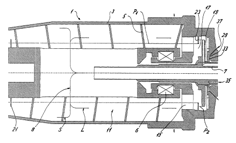
Figure 1 illustrates a solid bowl screw centrifuge 1 with a drum 3 having a
horizontal axis of rotation in which a screw is arranged. The drum 3 and the
screw 5
each of an essentially cylindrical section and a section which conically
tapers here.
An axially extending centric feed pipe 7 is used for feeding the centrifuge
material 8 by way of a distributor 9, which here is perpendicular with respect
to the
feed pipe 7, into the centrifuging chamber 11 between the screw 5 and the drum
3.
When, for example, a sludgy pulp is fed into the centrifuge, solid particles
are

deposited on the drum wall. A liquid phase develops farther toward the inside.
The screw 5 disposed by means of the bearing 6 rotates at a slightly lower or
higher speed than the drum 3 and conveys the centrifuged solids S toward the
conical
section out of the drum 3 to a solids discharge (not shown here).

3b


CA 02485082 2004-11-02

In contrast, the liquid flows to the larger drum diameter at the rearward end
of
the cylindrical section of the drum 3 and is guided there through a weir 15
into a
chamber 17 which axially adjoins the actual centrifuging chamber and has a
diameter
which is smaller in comparison to the centrifuging chamber.
A peeling disk 19 for discharging the liquid phase L is arranged in the
chamber 17 (see also Figure 2), which is adjoined by a discharge duct 20
discharging
the liquid phase L from the drum 3. The peeling disk 19 is arranged directly
on the
feed pipe 7 which is stationary during the operation, a sealed-off gap-free
arrangement being implemented between the peeling disk 19 and the feed pipe 7.
Preferably in the conically tapering area of the drum 3, the screw 1- in front
of the solids discharge (not shown here) - has a first siphon disk 21 which
extends
from the screw 5 radially toward the outside into the centrifuging chamber 11
and is
immersed into the liquid level P 1.
As a result of the immersion, the interior area or the centrifuging area in
the
centrifuging chamber 11 (here, to the right of the siphon disk 21) are
hermetically
sealed off with respect to the surroundings or the surrounding atmosphere. It
would
also be conceivable to arrange additional siphon disks in the conical area of
the drum
3 in order to influence the consistency of the solids in this manner (not
shown here).
In the chamber 17, a ring shoulder 23 is arranged on the side of the peeling
disk 19 pointing to the centrifuging chamber, which ring shoulder 23 extends
radially
from the inner circumference of the chamber 17 toward the inside.
A liquid level PI forms between the first siphon disk 21 and the ring shoulder
23 during the operation of the centrifuge because the siphon disk 21 and the
ring
shoulder overlap in the radial direction or because the two elements are
correspondingly adapted to one another.
In contrast, between the ring shoulder 23 situated closer to the peeling disk
19
and the peeling disk 19, the liquid level P2 extends to the inlet opening 25
of the
peeling disk. The liquid level can be varied here by slightly throttling the
peeling disk
19.
On the side of the peeling disk 19 facing away from the ring disk 23, the
chamber 17 extends radially toward the inside to close to the feed pipe or to
a

4


CA 02485082 2004-11-02

diameter smaller than the diameter of the screw 5, and leads into an axial
passage 27
which is adjoined in the axial direction by an annulus 29 which acts as a
blocking
chamber and which, in turn, leads into an axial discharge duct 31 for the
sealing liquid
on the outer circumference of the feed pipe 7 and of the discharge duct 31 for
the
centrifuge material, the inside diameter of the discharge duct 31 for the
sealing liquid
being smaller than the inside diameter of the passage 27, so that sealing
liquid
overflowing from the blocking chamber 29 flows out through the discharge duct
31.
In the blocking chamber or in the annulus 29, another siphon or blocking disk
33 is stationarily arranged on its inner circumference and extends from the
inside
radially to the outside into the blocking chamber.
An feed line 35 - here arranged parallel to the feed pipe 7 on its outer
circumference - leading into the centrifuge from the outside permits the
direct feeding
of sealing liquid, such as water, which is independent of the centrifuge
material, from
the inside into the blocking chamber 29.
A discharge bore 37 - here, leading on the circumference of the annulus 29 at
an acute angle with respect to the axis of rotation radially to the outside
out of the
drum 3 - permits the continuous discharge of sealing liquid from the annulus
29,
which causes an advantageous cleaning.
During the operation - that is, during rotations of the drum 3 and the screw 5-

a liquid level P3 of the sealing liquid forms in the annulus 29, which liquid
level P3
seals off the interior of the drum 3 against the surrounding atmosphere when
the
feeding amount of sealing liquid into the blocking chamber is larger than the
discharge amount, which is adjusted by the dimensioning of the discharge bore
37.
Excess water which does not flow off through the discharge bore 37 flows off
through
the discharge duct 3 1.
By means of the second siphon disk 33 in the blocking chamber 29, however,
a sufficient pressure can be built up in a simple manner, so that gas is kept
in the
liquid. By varying the diameter of the blocking and siphon disk 33, the
pressure in
the blocking chamber 29 can be varied. The pressure influences the type of the
conveyance of the solids and/or their consistency.
5


CA 02485082 2004-11-02

List of Reference Numbers

Solid bowl screw centrifuge 1
bearing 2
drum 3
screw 5
feed pipe 7
centrifuge material 8
distributor 9
centrifuging chamber 11
discharge duct 13
weir 15
chamber 17
peeling disk 19
discharge duct 20
blocking and siphon disk 21
ring shoulder 23
inlet opening 25
passage 27
annulus 29
discharge duct 31
blocking and siphon disk 33
feed line 35
discharge bore 37
liquid level Pl, P2, P3
centrifuge material S

6

Dessin représentatif
Une figure unique qui représente un dessin illustrant l'invention.
États administratifs

Pour une meilleure compréhension de l'état de la demande ou brevet qui figure sur cette page, la rubrique Mise en garde , et les descriptions de Brevet , États administratifs , Taxes périodiques et Historique des paiements devraient être consultées.

États administratifs

Titre Date
Date de délivrance prévu 2008-03-18
(86) Date de dépôt PCT 2003-05-27
(87) Date de publication PCT 2003-12-04
(85) Entrée nationale 2004-11-02
Requête d'examen 2005-02-23
(45) Délivré 2008-03-18
Expiré 2023-05-29

Historique d'abandonnement

Il n'y a pas d'historique d'abandonnement

Historique des paiements

Type de taxes Anniversaire Échéance Montant payé Date payée
Le dépôt d'une demande de brevet 400,00 $ 2004-11-02
Enregistrement de documents 100,00 $ 2004-11-23
Requête d'examen 800,00 $ 2005-02-23
Taxe de maintien en état - Demande - nouvelle loi 2 2005-05-27 100,00 $ 2005-04-14
Taxe de maintien en état - Demande - nouvelle loi 3 2006-05-29 100,00 $ 2006-04-21
Taxe de maintien en état - Demande - nouvelle loi 4 2007-05-28 100,00 $ 2007-04-17
Taxe finale 300,00 $ 2007-12-20
Taxe de maintien en état - brevet - nouvelle loi 5 2008-05-27 200,00 $ 2008-04-25
Taxe de maintien en état - brevet - nouvelle loi 6 2009-05-27 200,00 $ 2009-04-27
Taxe de maintien en état - brevet - nouvelle loi 7 2010-05-27 200,00 $ 2010-04-26
Taxe de maintien en état - brevet - nouvelle loi 8 2011-05-27 200,00 $ 2011-04-27
Taxe de maintien en état - brevet - nouvelle loi 9 2012-05-28 200,00 $ 2012-04-23
Taxe de maintien en état - brevet - nouvelle loi 10 2013-05-27 250,00 $ 2013-04-18
Taxe de maintien en état - brevet - nouvelle loi 11 2014-05-27 250,00 $ 2014-04-23
Taxe de maintien en état - brevet - nouvelle loi 12 2015-05-27 250,00 $ 2015-04-20
Taxe de maintien en état - brevet - nouvelle loi 13 2016-05-27 250,00 $ 2016-04-19
Taxe de maintien en état - brevet - nouvelle loi 14 2017-05-29 250,00 $ 2017-04-20
Taxe de maintien en état - brevet - nouvelle loi 15 2018-05-28 450,00 $ 2018-04-26
Taxe de maintien en état - brevet - nouvelle loi 16 2019-05-27 450,00 $ 2019-04-18
Taxe de maintien en état - brevet - nouvelle loi 17 2020-05-27 450,00 $ 2020-04-24
Taxe de maintien en état - brevet - nouvelle loi 18 2021-05-27 459,00 $ 2021-04-22
Titulaires au dossier

Les titulaires actuels et antérieures au dossier sont affichés en ordre alphabétique.

Titulaires actuels au dossier
WESTFALIA SEPARATOR AG
Titulaires antérieures au dossier
HERBERG, WOLF-DIETRICH
KRAMER, FRANZ
OSTKAMP, WILHELM
Les propriétaires antérieurs qui ne figurent pas dans la liste des « Propriétaires au dossier » apparaîtront dans d'autres documents au dossier.
Documents

Pour visionner les fichiers sélectionnés, entrer le code reCAPTCHA :


Pour visualiser une image, cliquer sur un lien dans la colonne description du document. Pour télécharger l'image (les images), cliquer l'une ou plusieurs cases à cocher dans la première colonne et ensuite cliquer sur le bouton "Télécharger sélection en format PDF (archive Zip)" ou le bouton "Télécharger sélection (en un fichier PDF fusionné)".

Liste des documents de brevet publiés et non publiés sur la BDBC .

Si vous avez des difficultés à accéder au contenu, veuillez communiquer avec le Centre de services à la clientèle au 1-866-997-1936, ou envoyer un courriel au Centre de service à la clientèle de l'OPIC.


Description du
Document 
Date
(yyyy-mm-dd) 
Nombre de pages   Taille de l'image (Ko) 
Abrégé 2004-11-02 2 118
Revendications 2004-11-02 4 122
Dessins 2004-11-02 2 97
Description 2004-11-02 6 281
Dessins représentatifs 2005-01-18 1 45
Page couverture 2005-01-18 1 80
Description 2007-06-05 8 367
Revendications 2007-06-05 7 277
Page couverture 2008-02-21 1 81
Taxes 2008-04-25 1 35
Poursuite-Amendment 2005-02-23 1 26
PCT 2004-11-02 4 154
Cession 2004-11-02 4 115
Cession 2004-11-23 3 92
PCT 2004-11-03 12 625
Poursuite-Amendment 2007-02-13 2 70
Taxes 2007-04-17 1 36
Poursuite-Amendment 2007-06-05 15 618
Correspondance 2007-12-20 1 31