Sélection de la langue

Search

Sommaire du brevet 2487580 

Énoncé de désistement de responsabilité concernant l'information provenant de tiers

Une partie des informations de ce site Web a été fournie par des sources externes. Le gouvernement du Canada n'assume aucune responsabilité concernant la précision, l'actualité ou la fiabilité des informations fournies par les sources externes. Les utilisateurs qui désirent employer cette information devraient consulter directement la source des informations. Le contenu fourni par les sources externes n'est pas assujetti aux exigences sur les langues officielles, la protection des renseignements personnels et l'accessibilité.

Disponibilité de l'Abrégé et des Revendications

L'apparition de différences dans le texte et l'image des Revendications et de l'Abrégé dépend du moment auquel le document est publié. Les textes des Revendications et de l'Abrégé sont affichés :

  • lorsque la demande peut être examinée par le public;
  • lorsque le brevet est émis (délivrance).
(12) Brevet: (11) CA 2487580
(54) Titre français: MECANISME D'ENTRAINEMENT SANS BATI-MOTEUR POUR ELEVATEUR
(54) Titre anglais: DRIVE UNIT, WITHOUT ENGINE FRAME, FOR A LIFT
Statut: Octroyé
Données bibliographiques
(51) Classification internationale des brevets (CIB):
  • B66B 11/00 (2006.01)
  • B66B 11/04 (2006.01)
  • B66B 11/08 (2006.01)
  • H02K 7/10 (2006.01)
  • H02K 7/102 (2006.01)
  • H02K 7/116 (2006.01)
(72) Inventeurs :
  • CHOLINSKI, ANDRZEJ (Suisse)
  • KUETTEL, HEINRICH (Suisse)
(73) Titulaires :
  • INVENTIO AG (Suisse)
(71) Demandeurs :
  • INVENTIO AG (Suisse)
(74) Agent: RICHES, MCKENZIE & HERBERT LLP
(74) Co-agent:
(45) Délivré: 2012-04-03
(22) Date de dépôt: 2004-11-12
(41) Mise à la disponibilité du public: 2005-05-13
Requête d'examen: 2009-10-28
Licence disponible: S.O.
(25) Langue des documents déposés: Anglais

Traité de coopération en matière de brevets (PCT): Non

(30) Données de priorité de la demande:
Numéro de la demande Pays / territoire Date
03 405807.3 Office Européen des Brevets (OEB) 2003-11-13

Abrégés

Abrégé français

Le présent mécanisme d'entraînement (1) consiste au moins en un moteur (2A), un support de moteur (3), un bloc d'appui (4), une poulie d'entraînement (5) et un accessoire de contre- rouleau (6). La poulie d'entraînement (5) est montée sur le support de moteur (3) et sur le bloc d'appui (4) au moyen d'un axe (15). Le frein respectif (7) est aménagé au bloc d'appui (4), de chaque côté. Les parois (8, 9) raccordent le support de moteur (3) au bloc d'appui (4). Le support de moteur (3), le bloc d'appui (4) et les parois (8, 9) forment une structure stable sans nécessiter de support de moteur (3) portant un bâti-moteur, ni bloc d'appui (4). L'accessoire de contre- rouleau (6) qui consiste en plaques latérales (12) et en contre-rouleau (13) est disposé directement sur le support de moteur (3) et le bloc d'appui (4).


Abrégé anglais

This drive unit (1) consists substantially of at least one motor (2A), a motor stand (3), a bearing block (4), a drive pulley (5) and a counter-roller attachment (6). The drive pulley (5) is mounted at the motor stand (3) and at the bearing block (4) by means of a shaft (15). A respective brake (7) is arranged at the bearing block (4) at each side. Webs (8, 9) connect the motor stand (3) with the bearing block (4). Motor stand (3), bearing block (4) and the webs (8, 9) form a stable structure without an engine frame carrying motor stand (3) and bearing block (4) being necessary. The counter-roller attachment (6) consisting of side plates (12) and counter-roller (13) is arranged directly at the motor stand (3) and the bearing block (4).

Revendications

Note : Les revendications sont présentées dans la langue officielle dans laquelle elles ont été soumises.


Claims:


1. Frameless drive unit for a lift, consisting of at least one motor, at least
one brake, a drive
pulley arranged between end plates and a brake disc with rim gear, in which a
gear pinion of an
evacuating motor engages in evacuating operation, is arranged at the drive
pulley, and wherein
the motor is arranged at one end plate and each end plate is carried by a
pedestal.

2. Frameless drive unit according to claim 1, characterised in that the end
plates are
connected by means of webs.

3. Frameless drive unit according to one of claims 1 and 2, characterised in
that the drive
pulley is carried by a shaft which is mounted at a motor stand serving as end
plate and at a
bearing block serving as end plate, wherein the motor is arranged at the motor
stand or at the
bearing block and the rotor of the motor is carried by a free end of the
shaft.

4. Frameless drive unit according to claim 1, characterised in that a counter-
roller
attachment, which enables different cable run spacings, is mountable at the
end plates.

5. Frameless drive unit according to any one of claims 1 to 4, characterised
in that the at
least one brake which acts by means of a corresponding brake shoe on the brake
disc is
arranged at least at one end plate.

6. Frameless drive unit according to claim 5, characterised in that each of
the at least one
brake has a brake calliper which is mounted to be floating and carries the
corresponding brake
shoe and at which a carrier plate carrying an actuator is supported, wherein
compression springs
are supported at one end at the carrier plate and at the other end at a
pressure plate, wherein the
pressure plate transmits the spring force of the compression springs to
another brake shoe by
means of pins guided by the brake calliper and for release of the brake the
activated actuator acts by
means of a pull rod on the pressure plate and relieves the spring force on
said another brake shoe.
7. A frameless drive unit for an elevator, comprising:
at least one motor;
a drive pulley driven by said at least one motor;


6

at least one brake for braking said drive pulley including a brake disc with a
rim gear for
engaging a gear pinion of an evacuating motor arranged at said drive pulley,
said at least one
brake acting by means of a brake shoe on said brake disc;
said at least one brake having a brake caliper mounted to be floating and
carrying said brake
shoe and at which a carrier plate carrying an actuator is supported, wherein
compression
springs are supported at one end at said carrier plate and at another end at a
pressure plate,
wherein said pressure plate transmits a spring force of said compression
springs to another
brake shoe by pins guided by said brake caliper and for release of said at
least one brake said
actuator is activated to act by means of a pull rod on said pressure plate and
relieves the spring
force on said another brake shoe;
a pair of spaced end plates, said at least one motor being arranged at one of
said end plates
and said at least one brake being arranged at one of said end plates; and
a pair of pedestals, each said pedestal carrying one of said end plates.
8. A frameless drive unit for an elevator, comprising:
at least one motor;
a drive pulley driven by said at least one motor;
at least one brake for braking said drive pulley;
a pair of spaced end plates, said at least one motor being arranged at one of
said end plates,
said end plates being connected together to form a stable structure without
being supported by
an engine frame;
a pair of pedestals, each said pedestal carrying a respective one of said end
plates; and
a brake disc with a rim gear for engaging a gear pinion of an evacuating motor
arranged at said
drive pulley,
wherein said at least one brake acts by means of a brake shoe on said brake
disc arranged at
one of said end plates, and
wherein said at least one brake has a brake caliper mounted to be floating and
carries said
brake shoe and at which a carrier plate carrying an actuator is supported,
wherein compression
springs are supported at one end at said carrier plate and at another end at a
pressure plate,
wherein said pressure plate transmits a spring force of said compression
springs to another
brake shoe by pins guided by said brake caliper and for release of said brake
said actuator is
activated to act by means of a pull rod on said pressure plate and relieves
the spring force on
said another brake shoe.


7

9. A frameless drive unit for an elevator, comprising:
at least one motor;
a drive pulley driven by said at least one motor;
at least one brake for braking said drive pulley;
a brake disc with a rim gear for engaging a gear pinion of an evacuating motor
arranged at said
drive pulley; and
a pair of spaced end plates, said end plates being connected together to form
a stable structure,
said at least one motor and said at least one brake each being arranged at
either of said end
plates, wherein said at least one brake acts by a brake shoe on said brake
disc arranged at one
of said end plates, wherein said at least one brake has a brake caliper
mounted to be floating
and carries said brake shoe and at which a carrier plate carrying an actuator
is supported,
wherein compression springs are supported at one end at said carrier plate and
at another end
at a pressure plate, wherein said pressure plate transmits a spring force of
said compression
springs to another brake shoe by pins guided by said brake caliper and for
release of said brake
said actuator is activated to act by means of a pull rod on said pressure
plate and relieves the
spring force on said another brake shoe, whereby said at least one motor, said
at least one
brake and said end plates form a standalone structure that operates with said
drive pulley as
the elevator drive unit.

10. The frameless drive unit according to claim 9 wherein said end plates are
connected by
webs to form the stable structure without being supported.

11. The frameless drive unit according to claim 9 wherein said drive pulley is
carried by a
shaft mounted at a motor stand being one of said end plates and mounted at a
bearing block
being another of said end plates, wherein said at least one motor is arranged
at said motor
stand or at said bearing block and a rotor of said at least one motor is
carried by a free end of
said shaft.

12. The frameless drive unit according to claim 9 including a counter-roller
attachment for
enabling different cable run spacings mounted directly at said end plates.

13. The frameless drive unit according to claim 9 comprising: a pair of
motors; said drive


8

pulley driven by said motors; a pair of brakes for braking said drive pulley;
and said motors
being arranged at associated ones of said end plates and said drive pulley and
said brakes
being arranged between said end plates.

14. The frameless drive unit according to claim 13 wherein said end plates are
connected
by webs.

15. The frameless drive unit according to claim 9 wherein said end plates are
connected by
webs to form the stable structure without being supported and said webs
include an upper web
and at least one lateral web spaced from said upper web.

16. The frameless drive unit according to claim 9 wherein said end plates are
connected by
webs to form the stable structure without being supported and said webs
include a box-shaped
upper web.

17. The frameless drive unit according to claim 9 wherein said end plates are
connected by
webs to form the stable structure without being supported and said webs
include at least one
wedge-shaped lateral web.

Description

Note : Les descriptions sont présentées dans la langue officielle dans laquelle elles ont été soumises.


CA 02487580 2011-08-31

I
Description:

Drive unit, without engine frame, for a lift
Field of the Invention

The invention relates to a drive unit, without engine frame, for a lift,
consisting of at least one
motor, at least one brake and a drive pulley arranged between end plates,
wherein the motor is
arranged at one end plate.

Background of the Invention

A drive unit consisting essentially of a electric motor, a motor stand, a
bearing block, a drive
pulley and an engine frame with counter-roller attachment has become known
from EP
03002866.6. The stator of the electric motor is screw-connected with the motor
stand by
means of a flange. The rotor of the electric motor is seated on a free end of
a shaft which
carries the drive pulley and which is mounted at the bearing block and at the
motor stand. The
drive pulley is mounted at the motor stand and the bearing block by means of
the shaft. A
brake is arranged in the inner region of the motor stand and covered by a
casing.

A disadvantage of the known equipment resides in the fact that the brake is
arranged to be
disposed internally. Access to the brake parts for maintenance is difficult.
The engine
frame, which carries the bearing block and the motor stand and which makes
construction
inconvenient and increases the cost of the entire drive unit, is also
disadvantageous.
Summary of the Invention

Here the invention will provide a remedy. The invention, meets the object of
avoiding the
disadvantages of the known equipment and of creating a lift drive with a brake
which
operates reliably in every case and is of simple construction.

In one aspect, the present invention resides in frameless drive unit for a
lift, consisting of at
least one motor, at least one brake, a drive pulley arranged between end
plates and a brake
disc with rim gear, in which a gear pinion of an evacuating motor engages in
evacuating


CA 02487580 2011-08-31

2
operation, is arranged at the drive pulley, and wherein the motor is arranged
at one end plate
and each end plate is carried by a pedestal.

In another aspect, the present invention resides in a frameless drive unit for
an elevator,
comprising: at least one motor; a drive pulley driven by said at least one
motor; at least one
brake for braking said drive pulley including a brake disc with a rim gear for
engaging a gear
pinion of an evacuating motor arranged at said drive pulley, said at least one
brake acting by
means of a brake shoe on said brake disc; said at least one brake having a
brake caliper
mounted to be floating and carrying said brake shoe and at which a carrier
plate carrying an
actuator is supported, wherein compression springs are supported at one end at
said carrier
plate and at another end at a pressure plate, wherein said pressure plate
transmits a spring
force of said compression springs to another brake shoe by pins guided by said
brake caliper
and for release of said at least one brake said actuator is activated to act
by means of a pull rod
on said pressure plate and relieves the spring force on said another brake
shoe; a pair of
spaced end plates, said at least one motor being arranged at one of said end
plates and said at
least one brake being arranged at one of said end plates; and a pair of
pedestals, each said
pedestal carrying one of said end plates.

In another aspect, the present invention resides in a frameless drive unit for
an elevator,
comprising: at least one motor, a drive pulley driven by said at least one
motor; at least one
brake for braking said drive pulley; a pair of spaced end plates, said at
least one motor being
arranged at one of said end plates, said end plates being connected together
to form a stable
structure without being supported by an engine frame; a pair of pedestals,
each said pedestal
carrying a respective one of said end plates; and a brake disc with a rim gear
for engaging a
gear pinion of an evacuating motor arranged at said drive pulley, wherein said
at least one
brake acts by means of a brake shoe on said brake disc arranged at one of said
end plates, and
wherein said at least one brake has a brake caliper mounted to be floating and
carries said
brake shoe and at which a carrier plate carrying an actuator is supported,
wherein compression
springs are supported at one end at said carrier plate and at another end at a
pressure plate,
wherein said pressure plate transmits a spring force of said compression
springs to another
brake shoe by pins guided by said brake caliper and for release of said brake
said actuator is
activated to act by means of a pull rod on said pressure plate and relieves
the spring force on
said another brake shoe.


CA 02487580 2011-08-31

2a
In another aspect, the present invention resides in a frameless drive unit for
an elevator,
comprising: at least one motor; a drive pulley driven by said at least one
motor; at least one
brake for braking said drive pulley; a brake disc with a rim gear for engaging
a gear pinion of an
evacuating motor arranged at said drive pulley; and a pair of spaced end
plates, said end plates
being connected together to form a stable structure, said at least one motor
and said at least
one brake each being arranged at either of said end plates, wherein said at
least one brake acts
by a brake shoe on said brake disc arranged at one of said end plates, wherein
said at least
one brake has a brake caliper mounted to be floating and carries said brake
shoe and at which
a carrier plate carrying an actuator is supported, wherein compression springs
are supported at
one end at said carrier plate and at another end at a pressure plate, wherein
said pressure plate
transmits a spring force of said compression springs to another brake shoe by
pins guided by
said brake caliper and for release of said brake said actuator is activated to
act by means of a
pull rod on said pressure plate and relieves the spring force on said another
brake shoe,
whereby said at least one motor, said at least one brake and said end plates
form a standalone
structure that operates with said drive pulley as the elevator drive unit.

The advantages achieved by the invention are substantially to be seen in that
a drive unit with
a short shaft and thus a small constructional length of the drive unit can be
realised. It is
additionally advantageous that the brake air cylinder and feed lines are
arranged
separately from the brake disc. In the case of leakage or line rupture, the
brake surfaces
cannot be contaminated with oil. Brake operational readiness remains
guaranteed. It is
further of advantageous that with the construction of the drive unit without
an engine frame
more freedom exists for cable guidance between the drive pulley arid the
counter-roller.
Larger cable run spacings are thereby made possible. The drive unit conceived
for large lift
cages and for large transport heights and high travel speeds has, for example,
a
constructional height of more than two metres and a total weight of more than
ten tonnes, wherein
weight and costs can be saved by the construction without engine frame.

Brief Description of the Drawings

The present invention is explained in more detail on the basis of the
accompanying figures, in
which:

Fig. 1 and Fig. 1 a show a drive unit according to the invention with a motor,


CA 02487580 2011-08-31

2b
Fig. 2 shows a motor stand with drive pulley and webs,

Fig. 3 shows a bearing block with bearing housing and drive pulley,
Fig. 4 shows an upper web,

Fig. 5 shows a lateral web,

Fig. 6 and Fig. 7 show details of a brake and

Fig. 8 shows a drive unit according to the invention with two motors.
Detailed Description of the Preferred Embodiments

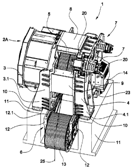
Fig. 1 shows the drive unit 1 assembled to finished state and substantially
Consisting of a motor 2A, a
motor stand 3 serving as an end plate, a bearing block 4 serving as an end
plate, a drive pulley 5
and a counter-roller attachment 6. The stator 2.1 of the electric motor 2A is
arranged at the motor
stand 3. The rotor 2.2 of the electric motor 2A is seated on a free end of a
shaft 15 which carries the
drive pulley 5 and which is mounted at the bearing block 4 and the motor stand
3. The free shaft
end projects beyond the motor stand 3. The drive pulley 5 is mounted at the
motor stand 3 and the
bearing block 4 by means of the shaft. A brake 7 is arranged at the bearing
block 4 at each side.
Webs 8, 9 connect the motor stand 3 with the bearing block 4, wherein, for
example, an upper web 8
and a respective lateral web 9 per side are provided. Motor stand 3, bearing
block 4 and the webs 8, 9
form a stable structure without a machine frame carrying motor stand 3 and
bearing block 4 being
necessary. Motor stand 3 and bearing block 4 are carried by means of support
elements 10
respectively at an arm 3.1 and an arm 4.1, without engine frame, on a
respective pedestal 11
or support. The counter-roller


CA 02/487580 2004-11-12
3

attachment 6 consisting of side plates 12 and counter-roller 12 is arranged
directly at the
motor stator 3 and bearing block 4. A hydraulic unit 14 serves for supply of
the actuator of
the brake 7. The actuator can also be electrically operated.

Support cables 25 form the cable run and are led on the one hand from the
drive pulley 5
over the counter-roller 13 and on the other hand from the drive pulley 5
directly into the lift
shaft. The cable run spacing is settable by means of the counter-roller
attachment 6,
wherein the side panels 12 are screw-connected at bores 12.1 with the motor
stand 3 and
with the bearing block 4, respectively.

Fig. 2 shows the motor stand 3 with drive pulley 5, the lateral webs 9 and the
upper web 8.
The bearing block 4 is shown in Fig. 3. A shaft 15 carrying the drive pulley 5
is mounted at
one end at the motor stand 3 and at the other end at the bearing block 4. The
bearing at
the bearing block side is denoted by 16. A brake disc 17 with rim gear 18, by
way of which
the drive pulley 5 is drivable in evacuating operation, is arranged at the
drive pulley 5.

Fig. 3 shows an internal view of the bearing block 4 with bearing housing 19
for reception
of the bearing 16. Moreover, eyes 20 at which the brake 7 is mounted are
visible. The
support surface for the upper web 8 is denoted by 21 and the support surfaces
for the
lateral webs 9 by 22, wherein the webs 8, 9 are, for example, screw-connected
with the
bearing block 4 and the motor stand 3.

The evacuating drive consists of a motor 23 with pinion 24, wherein for the
evacuating
operation the pinion 24 engages in the rim gear 18 and sets the drive pulley 5
in motion.
Fig. 4 shows the upper web 8, which is constructed to be box-shaped and the
support
surface 8.1 fits on the support surface 21.

Fig. 5 shows the lateral web 9, which is constructed to be wedge-shaped and
the support
surface 9.1 fits on the support surface 22.

Fig. 6 and Fig. 7 show the brake 7, which is arranged at the bearing block 4
at each side,
of the drive unit 1, wherein a brake calliper 30 is mounted in floating manner
at axles 31
penetrating the eyes 20. The brake calliper 30 can move through at most the
distance d
adjustable by means of setting screws 32, wherein a spring 33, which loads the
brake


CA 02487580 2004-11-12
4

calliper 30 in the direction of the drive pulley 5, is provided for each axle
31. The axles 31
are fixed to a support bracket 34 disposed in connection with the bearing
block 4. The
brake calliper 30 carries the inner brake shoe 40 at the drive pulley side and
serves as a
support for spacer tubes 35 and threaded rods 36, which fix a carrier plate 37
for a, for
example, hydraulic actuator 38. Compression springs 39 are supported at one
end at the
carrier plate 37 and at the other end at a pressure plate 41, which transmits
the spring
force of the compression springs 39 to the outer brake shoe 43 by means of
pins 42
guided by the brake calliper 30. For release of the brake 7 the activated
actuator 38 acts
by means of a pull rod 44 on the pressure plate 41 and relieves the spring
force of the
compression springs 39, which are arranged coaxially with the pull rod 44, on
the outer
brake shoe 43. In that case the brake calliper 30 moves, due to the spring
force of the
springs 33, in the direction of the brake pulley 5, wherein the inner brake
shoe 40 moves
away from the brake disc 17. A sensor 45 is provided for monitoring the state
of the brake.
Fig. 8 shows the drive unit 1, assembled to finished state, with two motors,
substantially
consisting of a motor 2A and a motor 2B, a motor stand 3 serving as an end
plate, a
bearing block 4 serving as an end plate, a drive pulley 5 and a counter-roller
attachment 6.
The shaft 15 carrying the drive pulley 5 and mounted at the end plates 3, 4
has two free
ends, wherein the rotor of one motor 2A is arranged at one free end and the
rotor of the
other motor 2B is arranged at the other free end.

Webs 8, 9 connect the motor stator 3 with the bearing block 4, wherein, for
example, an
upper web 8 and a respective lateral web 9 per side are provided. Motor stand
3, bearing
block 4 and the webs 8, 9 form a stable structure without an engine frame
carrying motor
stand 3 and support block 4 being necessary.

i

Dessin représentatif
Une figure unique qui représente un dessin illustrant l'invention.
États administratifs

Pour une meilleure compréhension de l'état de la demande ou brevet qui figure sur cette page, la rubrique Mise en garde , et les descriptions de Brevet , États administratifs , Taxes périodiques et Historique des paiements devraient être consultées.

États administratifs

Titre Date
Date de délivrance prévu 2012-04-03
(22) Dépôt 2004-11-12
(41) Mise à la disponibilité du public 2005-05-13
Requête d'examen 2009-10-28
(45) Délivré 2012-04-03

Historique d'abandonnement

Il n'y a pas d'historique d'abandonnement

Taxes périodiques

Dernier paiement au montant de 458,08 $ a été reçu le 2022-10-31


 Montants des taxes pour le maintien en état à venir

Description Date Montant
Prochain paiement si taxe applicable aux petites entités 2023-11-14 253,00 $
Prochain paiement si taxe générale 2023-11-14 624,00 $

Avis : Si le paiement en totalité n'a pas été reçu au plus tard à la date indiquée, une taxe supplémentaire peut être imposée, soit une des taxes suivantes :

  • taxe de rétablissement ;
  • taxe pour paiement en souffrance ; ou
  • taxe additionnelle pour le renversement d'une péremption réputée.

Les taxes sur les brevets sont ajustées au 1er janvier de chaque année. Les montants ci-dessus sont les montants actuels s'ils sont reçus au plus tard le 31 décembre de l'année en cours.
Veuillez vous référer à la page web des taxes sur les brevets de l'OPIC pour voir tous les montants actuels des taxes.

Historique des paiements

Type de taxes Anniversaire Échéance Montant payé Date payée
Enregistrement de documents 100,00 $ 2004-11-12
Le dépôt d'une demande de brevet 400,00 $ 2004-11-12
Taxe de maintien en état - Demande - nouvelle loi 2 2006-11-14 100,00 $ 2006-10-25
Taxe de maintien en état - Demande - nouvelle loi 3 2007-11-13 100,00 $ 2007-10-31
Taxe de maintien en état - Demande - nouvelle loi 4 2008-11-12 100,00 $ 2008-10-29
Requête d'examen 800,00 $ 2009-10-28
Taxe de maintien en état - Demande - nouvelle loi 5 2009-11-12 200,00 $ 2009-10-29
Taxe de maintien en état - Demande - nouvelle loi 6 2010-11-12 200,00 $ 2010-10-27
Taxe de maintien en état - Demande - nouvelle loi 7 2011-11-14 200,00 $ 2011-10-24
Taxe finale 300,00 $ 2012-01-20
Taxe de maintien en état - brevet - nouvelle loi 8 2012-11-13 200,00 $ 2012-10-31
Taxe de maintien en état - brevet - nouvelle loi 9 2013-11-12 200,00 $ 2013-11-04
Taxe de maintien en état - brevet - nouvelle loi 10 2014-11-12 250,00 $ 2014-11-03
Taxe de maintien en état - brevet - nouvelle loi 11 2015-11-12 250,00 $ 2015-11-02
Taxe de maintien en état - brevet - nouvelle loi 12 2016-11-14 250,00 $ 2016-10-31
Taxe de maintien en état - brevet - nouvelle loi 13 2017-11-14 250,00 $ 2017-10-30
Taxe de maintien en état - brevet - nouvelle loi 14 2018-11-13 250,00 $ 2018-10-29
Taxe de maintien en état - brevet - nouvelle loi 15 2019-11-12 450,00 $ 2019-11-05
Taxe de maintien en état - brevet - nouvelle loi 16 2020-11-12 450,00 $ 2020-10-29
Taxe de maintien en état - brevet - nouvelle loi 17 2021-11-12 459,00 $ 2021-10-29
Taxe de maintien en état - brevet - nouvelle loi 18 2022-11-14 458,08 $ 2022-10-31
Titulaires au dossier

Les titulaires actuels et antérieures au dossier sont affichés en ordre alphabétique.

Titulaires actuels au dossier
INVENTIO AG
Titulaires antérieures au dossier
CHOLINSKI, ANDRZEJ
KUETTEL, HEINRICH
Les propriétaires antérieurs qui ne figurent pas dans la liste des « Propriétaires au dossier » apparaîtront dans d'autres documents au dossier.
Documents

Pour visionner les fichiers sélectionnés, entrer le code reCAPTCHA :


Pour visualiser une image, cliquer sur un lien dans la colonne description du document. Pour télécharger l'image (les images), cliquer l'une ou plusieurs cases à cocher dans la première colonne et ensuite cliquer sur le bouton "Télécharger sélection en format PDF (archive Zip)" ou le bouton "Télécharger sélection (en un fichier PDF fusionné)".

Liste des documents de brevet publiés et non publiés sur la BDBC .

Si vous avez des difficultés à accéder au contenu, veuillez communiquer avec le Centre de services à la clientèle au 1-866-997-1936, ou envoyer un courriel au Centre de service à la clientèle de l'OPIC.


Description du
Document 
Date
(yyyy-mm-dd) 
Nombre de pages   Taille de l'image (Ko) 
Abrégé 2004-11-12 1 16
Description 2004-11-12 4 167
Revendications 2004-11-12 1 38
Dessins 2004-11-12 8 256
Dessins représentatifs 2005-04-18 1 21
Page couverture 2005-05-03 1 51
Description 2011-08-31 6 267
Revendications 2011-08-31 4 159
Dessins représentatifs 2012-03-06 1 24
Page couverture 2012-03-06 2 59
Cession 2004-11-12 4 128
Poursuite-Amendment 2009-10-28 1 53
Poursuite-Amendment 2011-08-31 20 873
Poursuite-Amendment 2011-05-18 2 60
Correspondance 2012-01-20 1 52