Sélection de la langue

Search

Sommaire du brevet 2488075 

Énoncé de désistement de responsabilité concernant l'information provenant de tiers

Une partie des informations de ce site Web a été fournie par des sources externes. Le gouvernement du Canada n'assume aucune responsabilité concernant la précision, l'actualité ou la fiabilité des informations fournies par les sources externes. Les utilisateurs qui désirent employer cette information devraient consulter directement la source des informations. Le contenu fourni par les sources externes n'est pas assujetti aux exigences sur les langues officielles, la protection des renseignements personnels et l'accessibilité.

Disponibilité de l'Abrégé et des Revendications

L'apparition de différences dans le texte et l'image des Revendications et de l'Abrégé dépend du moment auquel le document est publié. Les textes des Revendications et de l'Abrégé sont affichés :

  • lorsque la demande peut être examinée par le public;
  • lorsque le brevet est émis (délivrance).
(12) Demande de brevet: (11) CA 2488075
(54) Titre français: STRUCTURE D'ELECTRODE ET METHODES DE FABRICATION ET D'UTILISATION
(54) Titre anglais: ELECTRODE STRUCTURE AND METHODS FOR MAKING AND USING SAME
Statut: Réputée abandonnée et au-delà du délai pour le rétablissement - en attente de la réponse à l’avis de communication rejetée
Données bibliographiques
(51) Classification internationale des brevets (CIB):
  • A61N 1/04 (2006.01)
  • A61N 1/05 (2006.01)
  • C04B 41/88 (2006.01)
(72) Inventeurs :
  • SPECHT, HEIKO (Allemagne)
  • KRUEGER, FRANK (Allemagne)
(73) Titulaires :
  • W.C. HERAEUS GMBH
(71) Demandeurs :
  • W.C. HERAEUS GMBH (Allemagne)
(74) Agent: MACRAE & CO.
(74) Co-agent:
(45) Délivré:
(22) Date de dépôt: 2004-11-19
(41) Mise à la disponibilité du public: 2005-06-19
Licence disponible: S.O.
Cédé au domaine public: S.O.
(25) Langue des documents déposés: Anglais

Traité de coopération en matière de brevets (PCT): Non

(30) Données de priorité de la demande:
Numéro de la demande Pays / territoire Date
103 60 624.6-54 (Allemagne) 2003-12-19

Abrégés

Abrégé anglais


The invention relates to an electrode structure made of noble metal or a noble
metal alloy having
a thickness of .ltoreq.100 µm for implants, as well as to three methods for
its production. The
invention further relates to the use of such an electrode structure. The
electrode structure according
to the invention distinguishes itself in that this structure has an electrode
core made of gold,
silver, copper, or an alloy of at least two of these elements and in that the
electrode core is
completely encased by a first coating, which is formed from platinum, iridium,
or ruthenium.

Revendications

Note : Les revendications sont présentées dans la langue officielle dans laquelle elles ont été soumises.


-6-
Claims
1. Electrode structure (1) made of a noble metal or a noble metal alloy having
a thickness of
.ltoreq.100 µm for implants, characterized in that the electrode structure
(1 ) has an electrode core (2)
made of gold, silver, copper, or an alloy of at least two of these elements
and in that the electrode
core (2) is encased completely by a first coating (3; 3a, 3b), which is formed
from platinum,
iridium, or ruthenium.
2. Electrode structure (1) according to Claim 1, characterized in that the
electrode core (2) has a
thickness in a range of 5 µm to 99.8 µm.
3. Electrode structure (1) according to one of Claims 1 to 2, characterized in
that the first
coating (3; 3a, 3b) has a thickness in a range of 100 nm to 5 µm.
4. Electrode structure (1) according to one of Claims 1 to 3, characterized in
that the electrode
structure (1) has a thickness in a range of 7 µm to 30 µm.
5. Electrode structure (1) according to one of Claims 1-4, characterized in
that a second coating,
which is different from the first coating (3; 3a, 3b) and which is made of
ruthenium, ruthenium
oxide, iridium, iridium oxide, platinum, or titanium nitride, is formed on the
side of the first
coating (3; 3a, 3b) facing away from the electrode core (2).
6. Electrode structure (1) according to Claim 5, characterized in that the
second coating only
covers parts of the first coating (3; 3a, 3b).
7. Method for producing an electrode structure (1) according to one of Claims
1 to 6, characterized
in that
a) an electrically insulating surface (4a) of a substrate (4) is coated with a
metal layer (5), the
metal layer (5) is then coated with photoresist (6), and the photoresist (6)
is structured,
b) a first part of the first coating (3a) is galvanically generated on the now
exposed regions of
the metal layer (5),
c) the electrode core (2) is galvanically formed on the first part of the
first coating (3a),
d) the structured photoresist (6) is then removed from the metal layer (5),
e) the metal layer (5) is removed from the electrically insulating surface
(4a) of the substrate
(4) in the regions, which are not covered by the first part of the first
coating (3a),

-7-
f) the part of the electrode core (2) still free up to now from the first
coating (3a, 3b) is galvani-
tally coated with a second part of the first coating (3b),
g) the electrode structure (1) including the metal layer (5) is detached from
the electrically insu-
lating surface (4a) of the substrate (4), and
h) the metal layer (5) is then removed from the electrode structure (1).
8. Method for producing an electrode structure (1) according to one of Claims
1 to 6, character-
ized in that
a) an electrically insulating surface (4a) of a substrate (4) is provided with
a mask, and a metal
layer (5) is formed by cathode sputtering or vapor deposition on the regions
of the electri-
tally insulating surface (4a) not covered with the mask,
b) a first part of the first coating (3a) is generated by cathode sputtering
or vapor deposition on
the metal layer (5),
c) the electrode core (2) is then formed by cathode sputtering or vapor
deposition on the first
part of the first coating (3a),
f) the mask is then removed, and
g) at least the part of the electrode core (2) still free up to now from the
first coating (3a, 3b) is
galvanically coated with a second part of the first coating (3b),
h) the electrode structure (1) is then detached from the electrically
insulating surface (4a) of the
substrate (4), in that the metal layer (5) is removed.
9. Method for producing an electrode structure (1) according to one of Claims
1 to 6, character-
ized in that
a) an electrically insulating surface (4a) of a substrate (4) is coated with a
structured metal
layer, which forms a first part of the first coating (3a),
b) the first part of the first coating (3a) is provided with a mask, and the
electrode core (2) is
formed by cathode sputtering or vapor deposition only on the first part of the
first coating
(3a).
c) the part of the electrode core (2) still free up to now from the first
coating (3a) is then gal-
vanically coated with a second part of the first coating (3b), and
d) the electrode structure (1) is then detached from the electrically
insulating surface (4a) of the
substrate (4).
10. Method according to one of Claims 7, 8, or 9, characterized in that the
electrically insulating
surface (4a) of the substrate (4) is formed from glass or plastic.

-8-
11. Method according to Claim 7 or 8, characterized in that the metal layer
(5) is formed from
copper or gold.
12. Use of an electrode structure (1) according to one of Claims 1 to 6 for
stimulation elec-
trodes, cochlear electrodes, or retinal electrodes.

Description

Note : Les descriptions sont présentées dans la langue officielle dans laquelle elles ont été soumises.

CA 02488075 2004-11-19
Unser Zeichen: P10284 US
25. Oktober 2004
Electrode Structure and Methods for Making and Using Same
The invention relates to an electrode structure made of a noble metal or a
noble metal alloy
having a thickness of 900 um for implants, as welt as to three methods for its
production. The
invention further relates to the use of such an electrode structure.
Electrode arrangements made of noble metal are known, for example, from WO
02/089907 A1.
There, electrode structures are formed from platinum film and are fixed on a
carrier made of
plastic material. Such electrode arrangements are used, for example, for
cochlear implants.
tJS 6,266,568 B1 discloses an expandable cochlear electrode arrangement and a
method for its
production. There, a plurality of electrode contacts spaced from each other
are arranged on a
flexible carrier.
DE-OS 35 07 623 A1 discloses a long-term implantable sheet electrode having a
physiologically
inert matrix made of flexible plastic, which is coated with an electrical
conductor, for example
made of platinum. The coating is there formed galvanically or by vapor
deposition.
It is now an object of the invention to make available another electrode
structure for implants,
which can be produced simply and e~nomic211y. Furthermore, suitable methods
for its produc-
tion, as well as its use, should be provided.
The object is achieved for the electrode structure in that this structure has
an electrode core
made of gold, silver, copper, or an alloy of at least two of these elements,
and in that the elec-
trode core is completely encased by a first coating, which is formed from
platinum, iridium, or
ruthenium.
Such an electrode structure is economical, because it has a ductile electrode
core with good
conductivity made of a more economical material, which is merely encased by a
thin, more ex-

CA 02488075 2004-11-19
_2_
pensive coating, which is corrosion-resistant and biocompatible. Optionally,
an alloy formation
can be carried out between the electrode core and the first coating by a
heating process.
It has proven effective if the electrode core has a thickness in a range of
about 5 p.m to 99.8 p,m.
For the first coating, a thickness in a range of about 100 nm to 5 pm has
proven effective. Fortn-
ing the electrode structure with a thickness in a range of about 7 p,m to 30
~m is particularly
preferred.
Preferably, a second coating, which is different from the first coating and
which is made of ru-
thenium, ruthenium oxide, iridium, iridium oxide, platinum, or titanium
nitride, is formed on the
side of the first coating facing away from the electrode core. Here, it has
proven effective if the
second coating only covers parts of the first coating.
The object is realized in a first method, wherein
a) an electrically insulating surface of a substrate is coated with a metal
layer, the metal Payer
is then coated with photoresist, and the photoresist is structured,
b) a first part of the first coating is electroplated on the now exposed
regions of the metal layer,
c) the elecVode core is electroplated on the first part of the first coating,
d) the structured photoresist is then removed from the metal layer,
e) the metal layer is removed from the electrically insulating surtace of the
substrate in the re-
gions which are not covered by the first part of the first coating,
f) the part of the electrode core still free up to now from the first coating
is electroplated with a
second part of the first coating,
g) the electrode structure inGuding the metal layer is detached from the
electrically insulating
surface of the substrate, and
h) the metal layer is then removed from the electrode structure.
The object is realized in a second method, wherein
a) an electr7cally insulating surface of a substrate is provided with a mask
and a metal layer is
formed by cathode sputter7ng or vapor deposition on the regions of the
electrically insulating
surface not covered with the mask,
b) a first part of the first coating is generated on the metal layer by
cathode sputtering or vapor
deposition,
c) the electrode core is then formed by cathode sputtering or vapor deposition
on the first part
of the first coating,

CA 02488075 2004-11-19
-3-
f) the mask is then removed, and
g) at least the part of the electrode core still free up to now from the first
coating is electro-
plated with a second part of the first coating,
h) the electrode structure is then detached from the electrically insulating
surface of the sub-
strate, in which the metal layer is removed.
The object is realized in a third method, wherein
a) an electrically insulating surface of a substrate is coated with a
structured metal layer, which
forms a first part of the first coating,
b) the first part of the first coating is provided with a mask, and the
electrode core is formed
only on the first part of the first coating by cathode sputtering or vapor
deposition,
c) the part of the electrode core still free up to now from the first coating
is then electroplated
with a second part of the first coating, and
d) the electrode structure is then detached from the electrically insulating
surface of the sub-
strate.
Such methods are excellently suited to economical and fast production of the
electrode struc-
ture according to the invention.
In this way, the electrode core can be encased with several different
coatings. To form a second
coating on the first coating, for example with the third method, the
electrically insulating surface
of a substrate must then be coated with a structured metal layer, which forms
a first part of the
second coating, and then the first part of the first coating is formed
thereon. After forming the
electrode core and the second part of the first coating, a second part of the
second coating is
finally formed. Corresponding masks are used accordingly.
Here, it has proven effective, for the three methods according to the
invention, to form the elec-
trically insulating surface of the substrate from glass or plastic. A suitable
metal layer can be
formed preferably from copper or gold.
A use of the electrode structure according to the invention for a stimulation
electrode, cochlear
electrode, or retinal electrode is ideal.
Figures 1 a to 3g will explain the electrode structure according to the
invention, as well as its
production, by way of examples. Shown are:

CA 02488075 2004-11-19
-4-
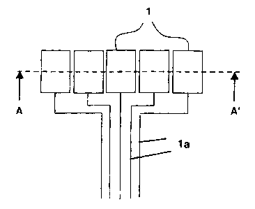
Fig. 1 several schematic diagrams of electrode structures with electrical
supply
lines in plan view,
Fig. 1a the schematic diagrams of the electrode structures from Fig. 1 in sec-
tionai view A-A',
Figs. 2a to 2d a third method for producing the electrode structure according
to the in-
vention, and
Figs. 3a to 3h a first method for producing the electrode structure according
to the in-
vention.
Figure 1 shows several electrode structures 1, here in an arbitrarily selected
arrangement rela-
tive to each other. Each electrode structure 1 is connected to an electrical
line 1a. However,
obviously any other arrangement can also be selected.
Figure 1a shows the section A-A' from Figure 1. Here, it can be seen that an
electrode structure
1 is constructed of an electrode core 2 and a first coating 3, which
completely surrounds the
electrode core 2.
Figures 2a-2d show the sequence of a third method according to the invention
for producing an
electrode structure 1 according to the invention. In Figure 2a, a first part
of a first coating 3a
made of iridium is vapor deposited on an electrically insulating surface 4a of
a substrate 4. Fig-
ure 2b illustrates that an electrode core 2 made of gold was vapor deposited
on the first part of
the first coating 3a. Figure 2c shows that a second part of the first coating
3b made of iridium
was galvanically deposited onto the electrode core 2. Figure 2d shows finally
the completed
electrode structure 1 detached from the substrate 4. The masks necessary for
vapor deposition
of the first part of the first coating 3a and the electrode core 2, which
cover the regions of the
substrate 4 lying next to these parts, are not shown.
Figures 3a-3h show the sequence of a first method according to the invention
for producing an
electrode structure 1 according to the invention. In Figure 3a, an
electrically insulating surface
4a made of glass for a substrate 4 is coated with a metal layer 5 made of
copper and a photore-
sist 6. The photoresist 8 is structured such that the metal layer 5 is
partially exposed via open-
ings 6a in the photoresist 6 (see Figure 3b). In the opening 6a, a first part
of a first coating 3a
made of platinum is then galvanically deposited (see Figure 3c). Figure 3d
illustrates that an
electrode core 2 made of copper was then galvanically deposited on the first
part of the first

CA 02488075 2004-11-19
-S-
coating 3a. Figure 3e shows that the photoresist 6 and also the resulting
exposed parts of the
metal layer 5 are now removed. Then, a second part of the first coating 3b
made of platinum is
galvanically generated (see Figure 3f). After removing the substrate 4, a part
of the metal layer
(see Figure 3g), which is yet to be removed, still remains on the electrode
structure. Figure 3h
shows finally the completed electrode structure 1 having the electrode core 2
and a first coating
3a, 3b.

Dessin représentatif
Une figure unique qui représente un dessin illustrant l'invention.
États administratifs

2024-08-01 : Dans le cadre de la transition vers les Brevets de nouvelle génération (BNG), la base de données sur les brevets canadiens (BDBC) contient désormais un Historique d'événement plus détaillé, qui reproduit le Journal des événements de notre nouvelle solution interne.

Veuillez noter que les événements débutant par « Inactive : » se réfèrent à des événements qui ne sont plus utilisés dans notre nouvelle solution interne.

Pour une meilleure compréhension de l'état de la demande ou brevet qui figure sur cette page, la rubrique Mise en garde , et les descriptions de Brevet , Historique d'événement , Taxes périodiques et Historique des paiements devraient être consultées.

Historique d'événement

Description Date
Demande non rétablie avant l'échéance 2010-11-19
Le délai pour l'annulation est expiré 2010-11-19
Inactive : Abandon.-RE+surtaxe impayées-Corr envoyée 2009-11-19
Réputée abandonnée - omission de répondre à un avis sur les taxes pour le maintien en état 2009-11-19
Inactive : CIB de MCD 2006-03-12
Demande publiée (accessible au public) 2005-06-19
Inactive : Page couverture publiée 2005-06-19
Lettre envoyée 2005-04-21
Inactive : Transfert individuel 2005-03-15
Inactive : Certificat de dépôt - Sans RE (Anglais) 2005-03-07
Inactive : Lettre de courtoisie - Preuve 2005-03-07
Inactive : CIB attribuée 2005-02-18
Inactive : CIB en 1re position 2005-02-18
Inactive : CIB attribuée 2005-02-18
Inactive : Lettre de courtoisie - Preuve 2005-01-18
Inactive : Certificat de dépôt - Sans RE (Anglais) 2005-01-13
Exigences de dépôt - jugé conforme 2005-01-13
Demande reçue - nationale ordinaire 2005-01-12

Historique d'abandonnement

Date d'abandonnement Raison Date de rétablissement
2009-11-19

Taxes périodiques

Le dernier paiement a été reçu le 2008-10-15

Avis : Si le paiement en totalité n'a pas été reçu au plus tard à la date indiquée, une taxe supplémentaire peut être imposée, soit une des taxes suivantes :

  • taxe de rétablissement ;
  • taxe pour paiement en souffrance ; ou
  • taxe additionnelle pour le renversement d'une péremption réputée.

Veuillez vous référer à la page web des taxes sur les brevets de l'OPIC pour voir tous les montants actuels des taxes.

Historique des taxes

Type de taxes Anniversaire Échéance Date payée
Taxe pour le dépôt - générale 2004-11-19
Enregistrement d'un document 2005-03-15
TM (demande, 2e anniv.) - générale 02 2006-11-20 2006-10-12
TM (demande, 3e anniv.) - générale 03 2007-11-19 2007-10-12
TM (demande, 4e anniv.) - générale 04 2008-11-19 2008-10-15
Titulaires au dossier

Les titulaires actuels et antérieures au dossier sont affichés en ordre alphabétique.

Titulaires actuels au dossier
W.C. HERAEUS GMBH
Titulaires antérieures au dossier
FRANK KRUEGER
HEIKO SPECHT
Les propriétaires antérieurs qui ne figurent pas dans la liste des « Propriétaires au dossier » apparaîtront dans d'autres documents au dossier.
Documents

Pour visionner les fichiers sélectionnés, entrer le code reCAPTCHA :


Pour visualiser une image, cliquer sur un lien dans la colonne description du document. Pour télécharger l'image (les images), cliquer l'une ou plusieurs cases à cocher dans la première colonne et ensuite cliquer sur le bouton "Télécharger sélection en format PDF (archive Zip)" ou le bouton "Télécharger sélection (en un fichier PDF fusionné)".

Liste des documents de brevet publiés et non publiés sur la BDBC .

Si vous avez des difficultés à accéder au contenu, veuillez communiquer avec le Centre de services à la clientèle au 1-866-997-1936, ou envoyer un courriel au Centre de service à la clientèle de l'OPIC.


Description du
Document 
Date
(aaaa-mm-jj) 
Nombre de pages   Taille de l'image (Ko) 
Dessins 2005-06-19 4 57
Description 2004-11-19 5 190
Abrégé 2004-11-19 1 14
Revendications 2004-11-19 3 96
Revendications 2004-11-19 4 57
Dessin représentatif 2005-05-25 1 4
Page couverture 2005-06-06 1 32
Certificat de dépôt (anglais) 2005-01-13 1 158
Certificat de dépôt (anglais) 2005-03-07 1 158
Courtoisie - Certificat d'enregistrement (document(s) connexe(s)) 2005-04-21 1 104
Rappel de taxe de maintien due 2006-07-20 1 110
Rappel - requête d'examen 2009-07-21 1 115
Courtoisie - Lettre d'abandon (taxe de maintien en état) 2010-01-14 1 174
Courtoisie - Lettre d'abandon (requête d'examen) 2010-02-25 1 165
Correspondance 2005-01-13 1 27
Correspondance 2005-03-07 1 26