Note : Les descriptions sont présentées dans la langue officielle dans laquelle elles ont été soumises.
CA 02489107 2004-11-26
041073CA.specification.doc
1
Energy Absorber For Horizontal Lifeline system
FIELD OF THE INVENTION
(001] The present invention relates to the field of fall protection systems,
and
particularly, to an energy absorber for use in a horizontal lifeline system.
BACKGROUND OF THE INVENTION
(002] It is known to provide horizontal lifeline safety systems for workers on
elevated structures.
(003] Such fall protection systems commonly consist of a horizontal lifeline
anchored at its ends to a building structure, including ceilings, walls and
roof
structures, and supported intermittently along its length by intermediate
supports.
Persons working in the vicinity of the lifeline may don a safety harness or
belt and
moveably attach to the horizontal lifeline via one or more mobile attachment
devices. The mobile attachment devices freely move along the horizontal
lifeline,
including across the intermediate supports.
(004] It is well known to include means for absorbing energy in such
horizontal
lifeline systems, so as to ensure that the maximum arrest forces exerted upon
persons using such fall protection systems do not exceed physically injurious
levels, and also to reduce the force placed on the anchorages therefor to
manageable levels.
(005] In modern fall protection systems, it is most common to utilize a
substantially inelastic lifeline and to delegate energy absorption
functionality to
separate energy absorption apparatus that does not exhibit undesirable
rebound.
(006) Energy absorption apparatus interposed between a horizontal lifeline and
its anchorage are most commonly termed "energy absorbers", and energy
absorption apparatus interposed between a lanyard and a harness are most
commonly termed "shock absorbers" but the terms are used somewhat
~W: ~ ~ h q~~. ~ n ~~ ~ , ~,
CA 02489107 2004-11-26
04lD73CA.specification.doc
2
interchangeably in the art, and indeed, many types ofi energy absorption
apparatus
are used interchangeably (to wit, in both applications). Accordingly, such
apparatus
are hereinafter referred to universally as "energy absorbers" for simplicity.
(007j United States Patent No. 5,598,900 (O'Rourke), issued February 4, 1997,
exemplifies one class of energy absorber of the prior art. in this energy
absorber, a
pair of rings is provided, which are secured to one another by a strip of tear-
ply
webbing material and by a strip of woven webbing material.
[008j In a fall, the tear-ply webbing separates incrementally, with consequent
absorption of energy, until such time as the energy absorber elongates to the
length of the woven webbing material, whereupon elongation stops, and further
loading is borne by the woven webbing material.
[009j This energy absorber is known to be relatively inexpensive to
manufacture,
and to provide satisfactory energy absorption, but, by virtue of its nature,
is useful
only for a single use, which is disadvantageous inter alia from the standpoint
of
economy.
[0010] United States Patent No. 5,197,573 (De La Fuente et al.), issued March
30,
1993, exemplifies another class of energy absorber.
[0011] This energy absorber, which is of all metal construction, and which
dissipates kinetic energy in a fall by rolling balls which are forced by a
tapered
surface on an expandable sleeve to frictionally load a force rod, is suitable
for
repetitive use, and as such, overcomes some of the drawbacks of the class
exemplified by the O'Rourke patent, but is of relatively complex and expensive
construction.
[0012] US Patent Publication No. 20040145098 to Thaler, provides an energy
absorber comprising a housing, a plunger and a compressible cushion. This
energy absorber is suitable for repetitive use, and as such, overcomes some of
the
drawbacks of the class exemplified by the O'Rourke patent, but is of
relatively more
expensive construction.
~v owax~,~,F. ,s,,.,~~.,,_~,-:~a,w~.a,~ra~"nrxv".:a~..~~.csnc--:~aa ..-
~.._~,....,.,_
CA 02489107 2004-11-26
04I073CA.specification.doc
3
SUMMARY OF THE INVENTION
(0013] It is an object of the present invention to provide an energy absorber
for
use in a horizontal lifeline system, which is of relatively simple and
inexpensive
construction as compared to devices of similar functionality of the prior art.
[0014] This object, among others, is attained by the present invention, an
energy
absorber for use in a horizontal lifeline system.
[0015] The invention provides an energy absorber for use in a horizontal
lifeline
system comprising an elongated non-elastic plate folded onto itself to form
adjoining lower wall portions, adjoining intermediate uvall portions
perpendicular to
the said lower wall portions, and opposed flanges in perpendicular
relationship to
said intermediate wall portions. The opposed flanges have means for receiving
connecting devices of the horizontal lifeline cable and an end anchor of the
horizontal lifeline system. The adjoining lower and intermediate wall portions
are
secured together with a plurality of distinct fasteners such that when a
tension
shock load produced in the horizontal lifeline cable by arresting a fall acts
in the
longitudinal direction of one of the opposed flanges, the fasteners deform,
pull
apart and fracture or shear, and the plate transforms into an unfolded state.
(0016] In one embodiment of the invention, the non-elastic plate is made of
stainless steel. The connecting fasteners are rivets and also made of
stainless
steel. The energy absorber of the present invention may optionally be coated
with
polymer coatings.
(0017] In use; the flange portions of the energy absorber are conventionally
secured by respective carabiners or quick links, so as. to operatively
interpose the
energy absorber between an anchorage point for the horizontal lifeline system
and
a horizontal lifeline.
CA 02489107 2004-11-26
041073CA.specification.doc
4
[0018] The horizontal lifeline system includes one or more mobile attachment
devices that the worker attaches to with a safety line. The mobile attachment
devices move freely along the lifeline including past the intermediary
supports.
[0019] in a fall situation, a tension load is applied to the horizontal
lifeline, which
in turn is transmitted to the opposing flanges of the energy absorber. As the
load is
applied, the folded adjoining intermediate and lower walls begin to be drawn
apart
by the load of the falling worker. As the force continues, some of the rivets
connecting the adjoining walls start to deform and pull apart and some
eventually
break such that the energy absorber transforms towards its unfolded state. The
action by the rivets effectively retards or dampens the rate at which the
adjoining
walls of the energy absorber are drawn apart, thereby reducing the maximum
arrest
force exerted on the falling worker, and decreasing loads on the anchorage.
[0020] Other advantages, features and characteristics of the present
invention, as
well as methods of operation and functions of the related elements of the
structure,
and the combination of parts and economies of manufacture, will become
apparent
upon consideration of the following detailed description and the appended
claims
with reference to the accompanying drawings, the latter of which are briefly
described hereinafter.
BRIEF DESCRIPTION O>: ThIE DRAW1NOS
[0021] The present invention may be further understood by reference to the
following detailed description of the embodiments of the invention, taken in
conjunction with the accompanying drawings, in which:
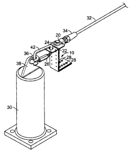
(0022] Figure 1 is an elevational perspective view of a section of a ceiling
mounted horizontal lifeline system showing use of the energy absorber of the
present invention.
[0023] Figure 2 is an elevational perspective view of a wall mounted
horizontal
lifeline system showing use of the energy absorber of the present invention.
CA 02489107 2004-11-26
041073CA.specification.doc
[0024 Figure 3 is a perspective view of the energy absorber of the present
invention situate in a horizontal lifeline system secured to a fall arrest
roof anchor.
[0025 Figure 4 is a view of the elongated folded plate portion of the energy
absorber of the present invention without the fasteners.
[0026] Figure 5 is a view of the elongated folded plate of the energy absorber
of
the present invention showing where the fasteners will be applied.
[0027 Figure 6 is the energy absorber of the present invention.
[0028 Figure 7 is a view of the energy absorber oaf the present invention in a
deformed state after a fall situation.
[0029 Although the above description and accompanying drawings relate to
specific preferred embodiments of the present invention as presently
contemplated
by the inventor, it will be understood that various changes, modifications and
adaptations may be made without departing from the spirit of the invention.
Detailed Description of Preferred Embodiment
(00301 Referring now generally to Figures 1, 2, 3 and 6 of the drawings, an
energy
absorber, for use in a horizontal lifeline system and according to a preferred
embodiment of the present invention is shown and designated with general
reference 10.
(0031 The energy absorber 10 is comprised of an elongated non-elastic plate 1
folded to form adjoining lower walls 12 and 14, adjoining intermediate walls
16 and
18 perpendicular to the lower walls, and opposed flanges 20 and 22 in
perpendicular relationship to the intermediate walls. The opposed flanges 20
and
22 are provided with apertures 24 and 26.
(0032 The adjoining lower and intermediate walls are secured together with a
plurality of distinct fasteners 28. At least two parallel rows of fasteners 28
are
provided on the said adjoining lower and intermediate waA portions. The
fasteners
are preferably corrosion resistant metal rivets.
CA 02489107 2004-11-26
041073CA.specification.doc
6
[0033] As indicated in Figure 3, the energy absorber 10 is shown in use in a
horizontal lifeline system such as one that may be employed on a building roof
(not
shown) or similar structure. The energy absorber 10 is conventionally secured
to an
end anchor support 30 and the horizontal lifeline cable 32 so as to
operatively
interpose the energy absorber 10 between the end anchor support 30 and the
horizontal lifeline cable 32. The lifeline cable 32 is secured to a swaged end
connection 34 that is in turn secured through aperture 24 of flange 20. A
shackle 36
is secured to the receiving projection 38 of the lifeline end support 39. A
carabiner
or snap ring 42 is secured at one end to the shackle 36 and at the other end
to the
aperture 26 of flange 22.
[0034] fn a fall situation, a falling person creates a force upon a mobile
attachment device 40, which force in turn is transmitted to the horizontal
lifeline
cable 32 thereby creating a tension shock load in the longitudinal direction
of
opposed flange 20 of the energy absorber 10. As the load created by the
falling
worker continues to be applied to the opposed flange 20 of the energy absorber
10,
some of fasteners 28 deform, and if the load continues the opposed flanges 20,
22
pull apart and in turn some fasteners 28 pull apart and fracture, and the
plate 1
transforms into an unfolded state. The kinetic energy from the fall is reduced
or
negated by the aforesaid deformation, fracturing and unfolding transformation
of the
energy absorber 10. Figure 7 shows the energy absorber 10 in an unfolded state
removed from the horizontal lifeline system. Fasteners 28 are sheared,
fractured or
broken. After a fall arrest occurrence a new energy absorber is installed in
the
horizontal lifeline system.
[0035] Referring now to Figure 9, the energy absorber 10 is shown in use in a
horizontal lifeline system such as one employed on an overhead ceiling (not
shown) structure. Only part of the overall system is shown. The horizontal
lifeline
system generally comprises an end anchor support 44 and several intermediate
anchor supports 48, which support the horizontal lifeline cable 32. It will be
understood that Figure 1 only illustrates one end anchor support 44 and two
intermediate supports 48. The horizontal lifeline system would generally
follow the
contour of the entire ceiling and would be provided with several intermediate
anchor
~~s ~~ .~~~.~
CA 02489107 2004-11-26
04/073CA.specification.doc
supports like 48 and an end anchor support at the other end of the system. A
mobile attachment device 40 is shown by one of the intermediate supports 48.
Several mobile attachment devices like device 40 may be located on the
horizontal
lifeline system. The mobile attachment device 40 freely moves across the
horizontal
lifeline cable 32 including across intermediate supports 48. A person working
in the
vicinity of the horizontal lifeline system attaches a safety line to the
mobile
attachment device 40.
(0036] Referring now to Figure 2, the energy absorber 10 is shown in use in a
horizontal lifeline system such as one employed on a wall (not shown)
structure.
The horizontal lifeline structure generally comprises end anchor supports 44
and
46, several intermediate anchor supports 48, 50, 52, two corner supports 54,
56,
and the horizontal lifeline cable 32. The energy absorber 10 is conventianally
secured to one end anchor support 44 in the manner described above. The other
end anchor support 46 is provided with a conventional tensioner 58 for
securing
and tensioning the horizontal lifeline cable 32 to said end anchor support 46.
A
mobile attachment device 40 is shown near intermediate support 52. The mobile
attachment device 40 freely moves across the horizontal lifeline cable 32
including
across the aforesaid intermediate and corner supports. A person working in the
vicinity of the horizontal lifeline system attaches a safety line to the
mobile
attachment device 40.
[0037] As indicated in Figure 4, the folded plate 1 of the energy absorber 10
is
shown before application of the fasteners (not shown). Adjoining lower walls
12
and 14 and adjoining intermediate walls 16 and 18 are provided with two
parallel
rows of apertures 27 for receiving the fasteners. Optionally, three parallel
rows of
apertures on each of adjoining lower walls 12 and 14 and adjoining
intermediate
walls 16 and 18 may be provided. Opposed flanges 20 and 22 are in
perpendicular
relationship to the intermediate wails 16 and 18. The opposed flanges 20 and
22
are provided with apertures 24 and 26.
[0038] The application of metal rivets 28 through apertures 27 of the folded
plate
1 forming the energy absorber 10 is shown in Figure 5. Adjoining lower walls
12
and 14 and adjoining intermediate walls 16 and 18 are provided with two
parallel
CA 02489107 2004-11-26
041073CA.specification.doc
8
rows of apertures for receiving the fasteners 28. Optionally, three parallel
rows of
apertures on each of adjoining lower walls 12 and 14 and adjoining
intermediate
walls 16 and 18 may be provided. Opposed flanges 20 and 22 are in
perpendicular
relationship to the intermediate walls 16 and 18. The opposed flanges 20 and
22
are provided with apertures 24 and 26.
(0039 The energy absorber 10 is preferably made of corrosion resistant metal
such as stainless steel. Optionally, the energy absorber may be additionally
coated
with a corrosion resistant coating such as a polymer coating.
(0040 The various components of the energy absorber described above may be
tailored (choice of materials, size, etc.) by persons of ordinary skill in the
art to meet
different energy absorption needs, using mechanical principles well known to
such
persons, which are accordingly not set out in detail herein.
__~.~z. _-._,b. -,.n=.~;".~,~c;~,.~.- .. . . =~'~'~"~..~-
.a~'i'R?~:.°.~, ,...~~...unm.,-....a~p.-~..,..~-
.~m~nmv.,."~...xaxema~..=, .. .x.. m....x
~:~~--_ .m~ee~.e.~,o,rwa.-