Note : Les descriptions sont présentées dans la langue officielle dans laquelle elles ont été soumises.
CA 02494663 2008-05-30
Description
Leakage indicator for a filter element of a filter
press
The invention relates to a leakage indicator for a
filter element of a filter press.
Filter presses with membrane filter elements are also
referred to as membrane filter presses and are known
from the prior art, for example from--German Patent DE
44 15 274 C2. In the case of filter presses of this
type, the customary pressure filtration is followed by
re-pressing, known as press filtration. In the
process, the filter cake that has built up in the
filter chamber is freed of the residual liquid still
present. For this purpose, the usually plate-shaped
filter element has at least one membrane, so that a
pressure-tight pressing space is produced between the
filter plate and the membrane. For pressing out, a
pressure medium is admitted to this pressure space and
makes the membrane expand. The pressure medium is in
this case usually supplied and removed through the bore
located in the edge of the filter element.
If a defect occurs to a membrane or to its fastening,
the pressure medium gets into the filter cake space,
which is also referred to as the filter chamber, and
leaves the filter press together with the filtrate
without being noticed. In cases of major leakage, a
loss of pressure medium is in fact established.
However, determination of the defective membrane plate
in the plate assembly is always very difficult and
time-consuming if the filter press has a large number
of filter elements.
CA 02494663 2008-05-30
2 -
European Patent Application En 1 084 742 Al discloses
an alerting device for leakages of filter elements of a
filter press in which a flow sensor with an impeller is
fitted into a corresponding connection bore, the
impeller being set in a rotational motion by the
pressure medium flowing in and out, which can be
visually monitored- A disadvantage of this solution is
that special requirements are imposed on the
arrangement of the required flow openings and their
angular positions in order to avoid. build-ups of the
pressure medium and to ensure adequate propulsion of
the impeller.
An object of the present invention is to provide a leakage
indicator which is of a particularly simple construction.
This object is achieved by a leakage indicator as
described hereinbelow. According to an aspect of the
invention, the leakage indicator has an indicator body,
which is arranged in a freely movable manner in a flow
space. The change in position of the indicator body
caused by the inflowing or outflowing pressure medium
can in turn be monitored visually or by sensors. To be
able to handle a very large volumetric flow of the
pressure medium, the cross section of the end portions
of the flow space is greater than the cross section of
the central part lying in between of the flow space.
The invention is substantially based on the fact that,
during pressing out, the stream of pressure medium in
an intact pressing membrane filter element comes to a
standstill when the maximum pressing-out pressure is
reached, since the pressing membrane comes to bear
against the filter cake and the pressing space is no
longer enlarged. While a change in the position of the
indicator body is brought about by the flowing pressure
medium when the pressing space is being filled or
emptied, without such a flow the indicator body remains
AMENDED SHEET
CA 02494663 2008-05-30
_ 3 -.
in a position of rest. If a leakage then occurs at the
membrane, the pressure medium flows into the filter
chamber and leaves. it together with the filtrate. The
stream of pressure medium produced in this way deflects
the indicator body out of its position of rest. This
change in position can be monitored, and consequently
serves both for indicating a loss of pressure medium
and for localizing the defective membrane filter
element. The last point in particular is of great
significance whenever the filter press has a
multiplicity of filter elements.
The use of an indicator body arranged in a freely
movable manner in the= flow space brings about a
significant structural simplification with regard to
the solutions known from the prior art. On the one
hand, this is because there is no longer any need for
all the components that serve for fastening the leakage
alerting device (impeller etc.). On the other hand,
the flow space can be given very small dimensions,
since it then only has to accommodate the freely
movable indicator body. As a result, the installation
space required for fitting the leakage indicator is
reduced.
A channel-shaped, that is to say elongate and
relatively narrowly confined, flow space has proven to
be particularly well suited for the present object, and
the space, advantageously has an inlet opening and an
outlet opening for the pressure medium at its
respective ends. In other words, the pressure medium
enters through the inlet opening at one end of the flow
space during the filling of the
AMENDED SHEET
CA 02494663 2008-05-30
4 _
pressing space, flows completely through the flow space
and at the opposite end of the flow space enters the
filter element through the outlet opening, to act there
on the pressing membrane. Compressed air or, in
particular to achieve high pressures above 6 bar, water
is preferably used as the pressure medium.
The central part advantageously has a cross section
which corresponds to the inflow cross section (claim
4),-so troublefree filling and emptying of the pressing
space is possible. Build-ups of the pressure medium
can consequently be effectively avoided.
In a particularly advantageous embodiment of the
invention, the flow space is arcuately formed. The
flow space preferably describes a virtually
complete circle, in particular in such a way that
the inlet opening and outlet opening are at the same
level. If the indicator body moves of its own
accord into a position of rest as soon as there is no
flow of the pressure medium, a starting or neutral
position is defined by this position of rest.
Any deviation from this position of rest consequently
indicates the occurrence of a pressure medium flow,
that is a leakage in the case of an already. filled
filter element. If the flow space is arranged in such
a way that the inlet opening and the outlet opening are
above the central part, the indicator body in effect
falls into the central part and finds its position of
rest there.
If the indicator body closes the flow space almost
completely in the region of its central part, that is
in its position of rest, a change in position of the
indicator body takes place even when there are the
smallest volumetric flows of the pressure medium, so
AMENDED SHEET
CA 02494663 2008-05-30
- 5 -
that a very high sensitivity of the leakage indicator
can be achieved.
At the same time, the bending of the flow space is of
great significance for the manner of the indication.
If the indicator body is deflected from its position of
rest in the central part of the flow space, its inertia
must first be overcome. At the same time, because of
the arcuate configuration of the flow space, and in
particular of the central part, the indicator body is
raised when there is a flow of the pressure medium. On
account of being constrained in the bent central part,
this raising takes place on the path of an arc of a
circle, so that the force of the flowing pressure
medium required for deflecting the indicator body has
an additional component which is characterized by a
sinusoidal function corresponding to the arc of the
circle. This makes it possible to register both very
small and very large pressure medium flows also in
terms of their quantity, by contrast with a central
part which is straight and for example extends
horizontally, in the case of which an indicator body
under the influence of the pressure medium would be
deflected completely in the direction of the outlet or
inlet opening in one motion, and a quantitative
evaluation of the deflection of the indicator body
-would not be possible.
The indicator body is preferably cylindrically formed
and preferably lies with its cylinder end faces
almost against the end faces of the flow space,
so that the flow space forms a kind of guide for the
indicator body. When the pressure medium flows
through, the indicator body serves as it were as a
float, while it moves in the flow space in the manner
of a rolling body when there is no pressure medium
AMENDED SHEET
CA 02494663 2008-05-30
6 -
flow. The indicating sensitivity of the indicator body
can be varied by the indicator body being produced as a
hollow cylinder and/or from materials of different
density, for example from metal, plastic or other
materials. Instead of a cylindrical indicator body, a
spherical indicator body or indicator body with some
other geometrical shape may of course also be used.
The arrangement of shut-off elements. ahead of the inlet
and outlet openings in the flow space, which prevent
blocking of these openings by the indicator body, is
particularly advantageous.
If a corresponding viewing plate is provided as a
covering of the flow space, the deflecting of the
indicator body from its position of rest can be
observed from the outside. The registering of the
change in position of the indicator body or the
registering of the position of the indicator body can
of course also take place by means of electrical or
other sensors. At the same time, in this case of a,
leakage occurring can be indicated by corresponding
indicating aids, for example optical signal
transmitters.
The inlet and outlet openings arranged in the flow
space are connected outside the flow space to
corresponding supply and removal lines, respectively.
The arrangement of these supply and removal lines on
the leakage indicator is freely selectable and
variable, so that the leakage indicator may be provided
in the pressure medium supply line, separately from the
filter element, or else be provided directly on the
filter element, for which the leakage indicator has
correspondingly formed mounting elements.
AMENDED SHEET
CA 02494663 2011-01-14
- 6a -
According to an aspect of the present invention, there is
provided a leakage indicator for a filter element of a
filter press, the filter element having at least one
membrane to be impinged by a pressure medium, the
leakage indicator comprising:
a flow space having an arcuate shape, said flow
space being defined by a separating element and a
circular surface opposite said separating element and
also by two opposed substantially planar surfaces, said
flow space having a central part with a cross section,
and said flow space having end portions interconnected
by said central part, said end portions having cross
sections greater than said cross section of said
central part and said end portions being connected to
the filter element to permit the pressure medium to
flow between the filter element and said end portions,
said flow space having ends and an inlet opening and
outlet opening respectively disposed at said ends;
an indicator body freely movable in said flow
space permitting a change in position of said indicator
body caused by inflowing or outflowing pressure medium
from or to the filter element, said change in position
to be monitored visually or by sensors, said indicator
body being dimensioned for maintaining an adequately
large open cross section for unhindered filling and
emptying of the filter element, when said indicator
body is positioned in one of said end portions; and
shut-off elements disposed at said ends of said
flow space and preventing blocking of said inlet and
outlet openings by said indicator body.
CA 02494663 2011-11-02
- 6b -
According to another aspect of the present invention,
there is provided a leakage indicator for a filter
element of a filter press, the filter element having at
least one membrane to be impinged by a pressure medium,
the leakage indicator comprising:
an arcuate flow space and an indicator body, said
flow space being defined by a separating element and a
circular surface opposite said separating element and
also by two opposed substantially planar surfaces;
said flow space having a central part with a cross
section, end portions interconnected by said central
part, said end portions having cross sections greater
than said cross section of said central part, and inlet
and outlet openings each connected to a respective one
of said end portions;
said inlet and outlet openings being connected to
the filter element to permit the pressure medium to
flow between the filter element and said end portions;
said indicator body being freely movable in said
flow space permitting a change in position of said
indicator body caused by inflowing or outflowing
pressure medium from or to said filter element, said
change in position to be monitored visually or by
sensors; and
shut-off elements disposed at said ends of said
flow space and preventing blocking of said inlet and
outlet openings by said indicator body.
According to a further aspect of the present invention,
there is provided a filter press assembly, comprising:
a filter element including at least one membrane
to be impinged by a pressure medium; and
CA 02494663 2011-01-14
- 6c -
a leakage indicator including an arcuate flow
space and an indicator body, said flow space being
defined by a separating element and a circular surface
opposite said separating element and also by two
opposed substantially planar surfaces;
said flow space having a central part with a cross
section, end portions interconnected by said central
part, said end portions having cross sections greater
than said cross section of said central part, and inlet
and outlet openings each connected to a respective one
of said end portions;
said inlet and outlet openings being connected to
said filter element to permit the pressure medium to
flow between said filter element and said end portions;
said indicator body being freely movable in said
flow space permitting a change in position of said
indicator body caused by inflowing or outflowing
pressure medium from or to said filter element, said
change in position to be monitored visually or by
sensors, said indicator body being dimensioned for
maintaining an adequately large open cross section for
unhindered filling and emptying of the filter element,
when said indicator body is positioned in one of said
end portions; and
shut-off elements disposed at said ends of said
flow space and preventing blocking of said inlet and
outlet openings by said indicator body.
CA 02494663 2010-04-14
7 -
The invention is explained in more detail below on the
basis of an exemplary embodiment, which is described on
the basis of drawings, in which:
Figure 1 shows a plan view of a leakage indicator
according to the invention,
Figure 2 shows a sectional representation of the
leakage indicator along the line AA in Figure
1.
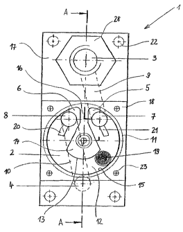
Figure 1 shows the leakage indicator 1 according to the
invention in a front view. The leakage indicator 1 has
a flow space or flow channel 2, which is arranged between
a pressure medium supply line 3, arranged above the flow
channel 2, and a pressure medium removal line 4, arranged
underneath the flow channel 2. The flow channel 2 is
arcuately formed, an opening being arranged in each of
its end portions 5, 6, serving as an inlet opening 7
and an outlet opening 8 for the pressure medium flowing
through the flow channel 2. The inlet opening 7 and
the outlet opening 8 are respectively connected to the
pressure medium supply line 3 and the pressure medium
removal line 4 by connecting channels 9, 10. It goes
without saying that it is likewise possible to connect
the inlet and outlet openings 7, 8 without connection
channels directly to the pressure medium supply line 3
and the pressure medium removal line 4, respectively,
so that the required installation or fitting space for
the leakage indicator 1 is further reduced.
The flow space or flow channel 2 is formed in such a way
that it is shaped in the form of an arc of a circle in a-
round opening 11. of the leakage indicator 1. In this case,
the end portions 5, 6 of the flow channel 2 have a
greater cross section than the central part 12 of the
flow channel 2, lying between these end portions 5, 6.
CA 02494663 2010-04-14
8 -
The central part 12 is bounded on the one hand by the
end face 13 of a circular-segmental separating element
14 and on the other hand by the rim 15 of the round
opening 11 lying opposite this end face 13. The
separating element 14 is arranged approximately
centrally in the round opening 11 and is connected to
the rim 15 of the round opening 11 by means of a
connecting web 16. It subdivides the round opening 11
into two flow channel halves arranged mirror-
symmetrically in relation to each other.
Guided between the base part 17 of the leakage
indicator 1, in which the round opening 11 has been
made, and the front covering 18, closing off the round
opening 11 and with it the flow space or flow channel 2,
is a cylindrical indicator body 19. The indicator body 19
substantially closes off the flow channel 2 in the
region of its central part 12. If the indicator body
19 is located in the region of the end portions 5, 6 of
the flow channel 2, cam-shaped shut-off elements 20,
21, which are provided ahead of the inlet opening 7 and
outlet opening 8, respectively, prevent the indicator
body 19 from blocking the outlet opening 8 and the
inlet opening 7 during filling and emptying. Provided
in all four corners of the base part 17 are boreholes
22 for the forming of screw connections or the like,
which serve for fastening the leakage indicator 1 to,
the filter element (not depicted).
The covering 18, closing off the flow channel 2 to the
front, is formed completely as a transparent viewing
plate, so that observation of the change in position of
the indicator body is possible from the outside. It
goes without saying that is is also possible to use a
covering which is only partly transparent, that is in
the region of the flow channel 2. The covering 18 is
securely fastened to the base part 17 of the leakage
indicator 1 by screws 23.
CA 02494663 2010-04-14
9 -
Figure 2 shows a sectional representation of the
leakage indicator 1 according to the invention along
the line AA in Figure 1. For the sake of overall
clarity, the indicator body is not depicted. The base
part 17 is preferably produced from a metal material or
a plastic. The round opening 11 and similarly the
special configuration of the flow channel 2 with the
separating element 14 and the inlet and outlet openings
7, 8 as well as the connecting channels 9, 10 are made
in the base part 17 by conventional machining methods,
for example milling.
The pressure medium removal line 4 is configured in
such a way that it can be connected directly to the
pressure medium connection of the filter element, for
example a filter plate (not depicted). For this
purpose, the rear side 24 of the leakage indicator 1 is
formed in a correspondingly planar manner. The
pressure medium supply line 3 and removal line 4 are
sealed by sealing elements 25, for example sealing
rings, a special connecting piece 28 which is adapted
in a way corresponding to the dimensioning used in this
case for the pressure medium connection (not depicted)
being introduced into the pressure medium supply line
3.
The transparent covering 18 has recesses 26 on its
outer edges, facing the flow space or flow channel 2. It is
supported on the one hand on shoulders 27 of the base
part 17, which are formed on both sides of the round
opening 11 and engage in the recesses 26, and on the
other hand on the separating element 14. The covering
18 is likewise provided with sealing elements 25 with
respect to the shoulders 27 and the separating element
14.
CA 02494663 2005-02-02
WO 2004/101104 PCT/EP2003/009423
- 10 -
List of designations
1 Leakage indicator
2 Flow channel
3 Pressure medium supply line
4 Pressure medium removal line
End portion
6 End portion
7 Inlet opening
8 Outlet opening
9 Connecting channel
Connecting channel
11 Round opening
12 Central part
13 End face
14 Separating element
Rim
16 Connecting web
17 Base part
18 Covering
19 Indicator body
Shut-off element
21 Shut-off element
22 Borehole
23 Screw
24 Rear side
Sealing ring
26 Recess
27 Shoulder
28 Connecting piece