Sélection de la langue

Search

Sommaire du brevet 2494674 

Énoncé de désistement de responsabilité concernant l'information provenant de tiers

Une partie des informations de ce site Web a été fournie par des sources externes. Le gouvernement du Canada n'assume aucune responsabilité concernant la précision, l'actualité ou la fiabilité des informations fournies par les sources externes. Les utilisateurs qui désirent employer cette information devraient consulter directement la source des informations. Le contenu fourni par les sources externes n'est pas assujetti aux exigences sur les langues officielles, la protection des renseignements personnels et l'accessibilité.

Disponibilité de l'Abrégé et des Revendications

L'apparition de différences dans le texte et l'image des Revendications et de l'Abrégé dépend du moment auquel le document est publié. Les textes des Revendications et de l'Abrégé sont affichés :

  • lorsque la demande peut être examinée par le public;
  • lorsque le brevet est émis (délivrance).
(12) Brevet: (11) CA 2494674
(54) Titre français: LOQUET A INERTIE POUR VERROU DE VEHICULE
(54) Titre anglais: INERTIA CATCH FOR A VEHICLE LATCH
Statut: Réputé périmé
Données bibliographiques
(51) Classification internationale des brevets (CIB):
  • E05B 77/06 (2014.01)
  • E05B 65/06 (2006.01)
(72) Inventeurs :
  • PEREVERZEV, IGOR (Etats-Unis d'Amérique)
(73) Titulaires :
  • INTIER AUTOMOTIVE CLOSURES INC. (Canada)
(71) Demandeurs :
  • INTIER AUTOMOTIVE CLOSURES INC. (Canada)
(74) Agent:
(74) Co-agent:
(45) Délivré: 2011-06-14
(86) Date de dépôt PCT: 2003-07-25
(87) Mise à la disponibilité du public: 2004-02-05
Requête d'examen: 2008-07-18
Licence disponible: S.O.
(25) Langue des documents déposés: Anglais

Traité de coopération en matière de brevets (PCT): Oui
(86) Numéro de la demande PCT: PCT/CA2003/001167
(87) Numéro de publication internationale PCT: WO2004/011749
(85) Entrée nationale: 2005-01-26

(30) Données de priorité de la demande:
Numéro de la demande Pays / territoire Date
60/398,978 Etats-Unis d'Amérique 2002-07-26

Abrégés

Abrégé français

La présente invention concerne un mécanisme de verrouillage (20) permettant de verrouiller sélectivement une porte (10) sur un véhicule automobile. Ce mécanisme de verrouillage comprend un crochet (22) mobile entre des positions de blocage et de déblocage par rapport à une barre de butée (24) fixée de manière inamovible au véhicule. Un levier de libération (30) est couplé fonctionnellement entre le crochet du verrou (22) et le mécanisme de verrouillage pour permettre un actionnement sélectif dudit crochet de verrou entre les positions de blocage et de déblocage. Un levier à inertie (50) peut s'accoupler au levier de libération (30) pour empêcher le déplacement du crochet du verrou (22) entre les positions de déblocage et de blocage. Le levier à inertie (50) est couplé mobile au mécanisme de verrouillage de manière à se déplacer pour entrer en contact avec le levier de libération (30) ou s'éloigner de celui-ci en réponse à une accélération seuil du véhicule. Une fente (42) formée dans le levier de libération (30) présente des côtés (44, 46) pouvant s'accoupler avec le levier à inertie (50) pour basculer automatiquement le levier à inertie en réponse au déplacement du levier de libération (30) dans le but d'empêcher le grippage du levier à inertie à l'intérieur du mécanisme de verrouillage par manque d'utilisation.


Abrégé anglais


A latch mechanism (20) for selectively latching a door (10) to an automotive
vehicle. The latch mechanism includes a latch hook (22) movable between locked
and unlocked positions relative to a striker bar (24) fixedly secured to the
vehicle. A release lever (30) is operatively coupled between the latch hook
(22) and the latch mechanism for selectively actuating the latch hook between
the locked and unlocked positions. An inertia lever (50) is engagable with the
release lever (30) to prevent movement of the latch hook (22) between the
unlocked and locked positions. The inertia lever (50) is movably coupled to
the latch mechanism for movement in and out of engagement with the release
lever (30) in response to a threshold acceleration of the vehicle. A slot (42)
is formed in the release lever (30) presenting sides (44, 46) engagable with
the inertia lever (50) to automatically rock the inertia lever in response to
movement of the release lever (30) to prevent seizing of the inertia lever
within the latch mechanism due to lack of use.

Revendications

Note : Les revendications sont présentées dans la langue officielle dans laquelle elles ont été soumises.


What is claimed is:

1. A latch mechanism for selectively latching a door to an automotive vehicle,

said latch mechanism comprising:
a latch hook movable between a locked position and an unlocked position;
a release lever operatively coupled to said latch hook for selectively moving
said latch hook from said locked to said unlocked position; and
an inertia lever movably supported within said latch mechanism and biased to
a first position;
wherein said release lever includes a slot and in a normal operating condition

said inertia lever is aligned with said slot to allow actuation of said
release lever, said
release lever slot presenting sides for engaging a portion of said inertia
lever for
automatically toggling said inertia lever away from said first position in
response to
movement of said release lever to prevent seizing of said inertia lever within
the latch
mechanism;
and wherein said inertia lever includes a counterweight portion for moving
said inertia lever out of alignment with said slot and into blocking
engagement with
said release lever in response to a side impact upon the vehicle in order to
prevent
actuation of said release lever and thereby inhibit movement of said latch
hook from
said locked position into said unlocked position.

2. A latch mechanism according to claim 1, wherein said inertia lever includes
a
tab and said slot of said release lever is aligned with and engages said tab
when said
release lever is actuated to unlock said latch hook when said inertia lever is
in said
first position.

3. A latch mechanism according to claim 2, wherein upon side impact said
inertia lever moves to said blocking engagement position such that said tab is
not
aligned with said slot.


4. A latch mechanism according to any of claims 1-3 , wherein said inertia
lever
is pivotally mounted within said latch mechanism.

5. A latch mechanism according to any of claims 1-4, wherein said release
lever
is pivotally mounted within the latch mechanism.

6. A latch mechanism for selectively latching a door to an automotive vehicle,

said latch mechanism comprising:
a housing including a first side and an opposite second side;
a latch hook disposed on said first side of said housing and moveable between
a locked position and an unlocked position;
a release lever disposed on said second side of said housing and operatively
coupled to said latch hook for selectively moving said latch hook from said
locked to
said unlocked position; and
an inertia lever movably supported on said second side of said housing and
biased via a spring to a first position;
wherein said release lever includes a slot and in a normal operating condition

said inertia lever is aligned with said slot to allow actuation of said
release lever, said
release lever slot presenting sides for engaging a portion of said inertia
lever for
automatically toggling said inertia lever away from said first position in
response to
movement of said release lever to prevent seizing of said inertia lever within
the latch
mechanism;
and wherein said inertia lever includes a counterweight portion for moving
said inertia lever into a second position out of alignment with said slot in
response to a
side impact upon the vehicle in order to prevent actuation of said release
lever and
thereby inhibit movement of said latch hook from said locked position into
said
unlocked position.

7. A latch mechanism for selectively latching a door to an automotive vehicle,

said latch mechanism comprising:
a latch hook moveable between a locked position and an unlocked position;
6


a release lever operatively coupled to said latch hook for selectively moving
said latch hook from said locked to said unlocked position;
an inertia lever including a counterweight portion movably supported within
said latch mechanism for blocking movement of said release lever in response
to a
side impact upon the vehicle;
means for biasing said inertia lever to a first position;
wherein said release lever includes a slot presenting sides for engaging a
portion of said inertia lever for automatically toggling said inertia lever in
response to
movement of said release lever to prevent seizing of said inertia lever within
the latch
mechanism;
wherein said inertia lever includes a tab and said slot of said release lever
is
aligned with and engages said tab when said release lever is actuated to
unlock said
latch hook when said inertia lever is in said first position;
wherein upon said side impact said inertia lever moves to a second position
such that said tab is not aligned with said slot to thereby block movement of
said
release lever.

8. A latch mechanism according to claim 7, wherein said inertia lever is
pivotally
mounted within the latch mechanism and said release lever is pivotally mounted
within the latch mechanism.

7

Description

Note : Les descriptions sont présentées dans la langue officielle dans laquelle elles ont été soumises.


CA 02494674 2005-01-26
WO 2004/011749 PCT/CA2003/001167
Inertia Catch for a Vehicle Latch

BACKGROUND OF THE INVENTION
1. Field of the Invention
The invention relates to a latch for selectively locking a door of an
automotive
vehicle, and more particularly, a lateral inertia lever for preventing the
release of the
latch in the event of a lateral vehicle impact.

2. Description of the Prior Art
Automotive vehicles include hinged doors for allowing and closing access to
passenger or cargo compartments within the vehicle. Typically, a latch
mechanism is
coupled between the door and the vehicle for releasably locking the door in a
closed
position with the vehicle. A release mechanism is typically coupled to the
latch
mechanism for selectively locking and unlocking the latch mechanism. It
remains
desirable to provide a mechanism for preventing the latch mechanism from
unlocking
duri ng a side impact upon the vehicle.

SUMMARY OF THE INVENTION
According to one aspect of the invention, a latch mechanism is provided for
selectively latching a door to an automotive vehicle. The latch mechanism
includes a
latch hook movable between locked and unlocked positions. A release lever is
operatively coupled to the latch hook for selectively moving the latch hook
between
the locked and unlocked positions. The latch mechanism includes an inertia
lever
engagable with the release lever to prevent movement of the latch hook between
the
locked and unlocked positions. The inertia lever is movably supported within
the
latch mechanism for moving in and out of engagement with the release lever in
response to a side impact upon the vehicle.

BRIEF DESCRIPTION OF THE DRAWINGS
1
SUBSTITUTE SHEET (RULE 26)


CA 02494674 2010-09-24

BRIEF DESCRIPTION OF THE DRAWINGS

Advantages of the present invention will be readily appreciated as the same
becomes better understood by reference to the following detailed description
when
considered in connection with the accompanying drawings wherein:
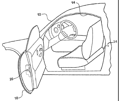
Figure 1 is a partial perspective view of an automotive vehicle incorporating
a
latch mechanism according to one embodiment of the invention;
Figure 2 is a partially exploded perspective view of the latch mechanism;
Figure 2a is a perspective view of a release ]ever in the latch mechanism; and
Figure 3 is a perspective view of the latch mechanism.

DETAILED DESCRIPTION OF THE PREFERRED EMBODIMENT

Referring to the figures, Figure 1 illustrates a door 10 for an automotive
vehicle 12 incorporating a latch 20 mechanism according to one embodiment of
the
invention. The door 10 is hinged to the vehicle 12 for pivotal movement
between a
closed position nested within an opening 14 in the vehicle and an opened
position to
allow access into the vehicle 12 through the opening 14. The latch mechanism
20 is
fixedly mounted to the door 10 for releasably locking the door 10 in the
closed
position.
Referring to Figures 1-3, the latch mechanism 20 includes a housing 19 having
a first side 21 and an opposite second side 23. A latch hook 22 is disposed on
the first
side 21 of the housing 19 and is lockably engagable with a striker bar 24
fixedly
secured to the vehicle 12. The latch hook 22 is movable between a locked
position
lockingly engaged with the striker bar 24 and an unlocked position disengaged
with
the striker bar 24 to allow movement of the door 12 between the closed and
opened
positions. The latch hook 22 is biased toward the locked position by a biasing
member (not shown) of any suitable variety, such as a clock spring extending
between
the latch mechanism 20 and the latch hook 22. A release lever 30 is pivotally
mounted to a mounting bracket 31 that is disposed on the second side 23 of the
housing 19 and is operatively coupled to the latch hook 22 for moving the
latch hook
2


CA 02494674 2010-09-24

22 between the locked and unlocked positions in response to clockwise and
counterclockwise movement of the release lever 30, as viewed in Figures 2 and
3_ A
detailed description of the structure and function of such a latch mechanism
20 is
disclosed in United States Patent 6,328,353 BI issued on December 11, 2001.
The release lever 30 includes a proximal end 32 pivotally coupled to the
mounting bracket 31 by a pivot pin 33 and an opposite distal end 34 extending
outwardly from the latch mechanism 20. The release lever 30 includes opposite
upper
and lower edges 36, 38 extending longitudinally between the proximal and
distal ends
32, 34. A raised abutment surface 40 is formed along a portion of the tower
edge 38
adjacent the distal end 34. A relief slot 42 is cut or formed in the lower
edge 38
between the proximal end 32 and the abutment surface 40. The slot 42 extends
between opposing first and second sides 44, 46. The first side 44 of the slot
42 and
the lower edge 38 intersect to present a generally raised abutment tip 48.
The latch mechanism 20 includes an inertia lever 50 extending between
opposite proximal and distal ends 52, 54. The distal end 54 is defined by a
bent tab
58 engagable with either the abutment surface 40 or the slot 42 in the release
lever 30.
The proximal end 52 of the inertia lever 50 is pivotally coupled to the
mounting
bracket 31 by a pivot pin 56 for moving the tab 58 between engagement with the
abutment surface 40 or the slot 42 A biasing member 60 extends between the
inertia
lever 50 and the housing 19 for biasing the inertia lever 50 in a
counterclockwise
direction, as viewed in the figures, towards engagement with a stop 62 formed
in the
mounting bracket 31. With the inertia lever 50 abutting the stop 62, the tab
58 is
presented for moving in and out of the slot 42 to allow counterclockwise and
clockwise movement of the release lever 30 about the pivot pin 33 for
actuating the
latch hook 22 between the unlocked and locked positions, respectively. The
first side
44 of the slot 42 and the tip 48 engage the tab 58 to lightly toggle the
inertia lever 50
in and out of contact with the stop 62 during clockwise and counterclockwise
rotation
of the release lever 30.
A weight 70 is fixedly secured to the inertia lever 50 between the proximal
and distal ends 52, 54 by any suitable means, such as welding or bolting. The
weight
70 has a predetermined mass and is secured to the inertia lever 50 at a
predetermined
distance from the pivot pin 56 to cause clockwise rotation of the inertia
lever 50
3


CA 02494674 2010-09-24

against the bias of the biasing member 60 beyond a threshold lateral
acceleration of
the vehicle generally associated with a side impact upon the vehicle.
In operation, under normal vehicle operating conditions, the release lever 30
is
rotated counterclockwise and clockwise for actuating the latch hook 22 between
the
unlocked and locked positions, respectively. The biasing member 60
continuously
biases the inertia lever 50 against the stop 62. As a result of this bias, the
release lever
30 is permitted to rotate counterclockwise to unlock the latch hook 22 because
the slot
42 is generally aligned with the tab 58 enabling the tab 58 to enter the slot
42. In
addition, the arcuate movement of the release lever 30, causes the first side
44 of slot
42 and the tip 48 to engage the tab 58 to rock the inertia lever 50 in and
slightly out of
contact with the stop 62 during clockwise and counterclockwise rotation of the
release
lever 30 to prevent the inertia lever 50 from binding on the pivot pin 56.
In the event of a side impact of the vehicle 12 or similar sudden
acceleration,
the weight 70 applies a torque moment upon the inertia lever 50 to cause the
inertia
lever 50 to rotate clockwise so that the tab 58 is presented for engaging the
abutment
surface 40. Should the release lever 30 rotate counterclockwise, the abutment
surface
40 will engage the tab 58. While engaged with the abutment surface 40, the tab
58
prevents actuation of the latch hook 22 to the unlocked position by preventing
counterclockwise movement of the release lever 30.
The invention has been described in an illustrative manner, and it is to be
understood that the terminology, which has been used, is intended to be in the
nature
of words of description rather than of limitation.
Many modifications and variations of the present invention are possible in
light of the above teachings- It is, therefore, to be understood that within
the scope of
the appended claims, the invention may be practiced other than as specifically
described.

4

Dessin représentatif
Une figure unique qui représente un dessin illustrant l'invention.
États administratifs

Pour une meilleure compréhension de l'état de la demande ou brevet qui figure sur cette page, la rubrique Mise en garde , et les descriptions de Brevet , États administratifs , Taxes périodiques et Historique des paiements devraient être consultées.

États administratifs

Titre Date
Date de délivrance prévu 2011-06-14
(86) Date de dépôt PCT 2003-07-25
(87) Date de publication PCT 2004-02-05
(85) Entrée nationale 2005-01-26
Requête d'examen 2008-07-18
(45) Délivré 2011-06-14
Réputé périmé 2017-07-25

Historique d'abandonnement

Il n'y a pas d'historique d'abandonnement

Historique des paiements

Type de taxes Anniversaire Échéance Montant payé Date payée
Le dépôt d'une demande de brevet 400,00 $ 2005-01-26
Taxe de maintien en état - Demande - nouvelle loi 2 2005-07-25 100,00 $ 2005-06-14
Enregistrement de documents 100,00 $ 2005-06-28
Taxe de maintien en état - Demande - nouvelle loi 3 2006-07-25 100,00 $ 2006-06-20
Taxe de maintien en état - Demande - nouvelle loi 4 2007-07-25 100,00 $ 2007-06-15
Taxe de maintien en état - Demande - nouvelle loi 5 2008-07-25 200,00 $ 2008-06-18
Requête d'examen 800,00 $ 2008-07-18
Taxe de maintien en état - Demande - nouvelle loi 6 2009-07-27 200,00 $ 2009-06-12
Taxe de maintien en état - Demande - nouvelle loi 7 2010-07-26 200,00 $ 2010-06-15
Taxe finale 300,00 $ 2011-03-31
Taxe de maintien en état - brevet - nouvelle loi 8 2011-07-25 200,00 $ 2011-06-14
Taxe de maintien en état - brevet - nouvelle loi 9 2012-07-25 200,00 $ 2012-06-26
Taxe de maintien en état - brevet - nouvelle loi 10 2013-07-25 250,00 $ 2013-06-12
Taxe de maintien en état - brevet - nouvelle loi 11 2014-07-25 250,00 $ 2014-07-09
Taxe de maintien en état - brevet - nouvelle loi 12 2015-07-27 250,00 $ 2015-07-01
Titulaires au dossier

Les titulaires actuels et antérieures au dossier sont affichés en ordre alphabétique.

Titulaires actuels au dossier
INTIER AUTOMOTIVE CLOSURES INC.
Titulaires antérieures au dossier
PEREVERZEV, IGOR
Les propriétaires antérieurs qui ne figurent pas dans la liste des « Propriétaires au dossier » apparaîtront dans d'autres documents au dossier.
Documents

Pour visionner les fichiers sélectionnés, entrer le code reCAPTCHA :


Pour visualiser une image, cliquer sur un lien dans la colonne description du document. Pour télécharger l'image (les images), cliquer l'une ou plusieurs cases à cocher dans la première colonne et ensuite cliquer sur le bouton "Télécharger sélection en format PDF (archive Zip)" ou le bouton "Télécharger sélection (en un fichier PDF fusionné)".

Liste des documents de brevet publiés et non publiés sur la BDBC .

Si vous avez des difficultés à accéder au contenu, veuillez communiquer avec le Centre de services à la clientèle au 1-866-997-1936, ou envoyer un courriel au Centre de service à la clientèle de l'OPIC.


Description du
Document 
Date
(yyyy-mm-dd) 
Nombre de pages   Taille de l'image (Ko) 
Dessins représentatifs 2005-01-26 1 11
Description 2005-01-26 4 198
Dessins 2005-01-26 3 71
Revendications 2005-01-26 1 42
Abrégé 2005-01-26 1 67
Page couverture 2005-04-01 1 47
Description 2010-09-24 4 169
Revendications 2010-09-24 3 91
Dessins 2010-09-24 3 61
Page couverture 2011-05-17 2 53
Dessins représentatifs 2011-05-17 1 14
Poursuite-Amendment 2008-07-18 1 27
Poursuite-Amendment 2010-03-24 2 68
PCT 2005-01-26 9 316
Cession 2005-01-26 5 158
Correspondance 2005-03-30 1 26
Cession 2005-06-28 3 86
Poursuite-Amendment 2009-07-30 1 30
Poursuite-Amendment 2010-09-24 16 547
Poursuite-Amendment 2010-09-27 16 626
Correspondance 2011-03-31 1 25